975-0428-01-01 Revision B
June 2008
Xantrex and Smart Choice For Power are trademarks of Xantrex International, registered in the U.S. and other countries. Other trademarks, registered trademarks, and product names are the property of
their respective owners and are used herein for identification purposes only. LinkLITE Owner’s Guide © June 2008 Xantrex International. All rights reserved.
Unless specifically agreed to in writing, Xantrex Technology Inc. (“Xantrex”): (a) makes no warranty as to the accuracy, sufficiency or suitability of any technical or other information provided in its
manuals or other documentation. (b) assumes no responsibility or liability for losses, damages, costs or expenses, whether special, direct, indirect, consequential or incidental, which might arise out of
the use of such information. The use of any such information will be entirely at the user’s risk; and (c) reminds you that if this manual is in any language other than English, although steps have been
taken to maintain the accuracy of the translation, the accuracy cannot be guaranteed. Approved Xantrex content is contained with the English language version which is posted at www.xantrex.com.
Xantrex and Smart Choice For Power sont marques de commerce de Xantrex International. Les autres marques de commerce, marques déposées et noms de produit sont la propriété de leurs propriétaires
respectifs et sont utilisés ici dans le seul but d’être identifiés. LinkLITE Manuel d’exploitation © June 2008 Xantrex International. Tous droits réservés. Sauf accord écrit explicite, Xantrex Technology Inc.
(« Xantrex ») (a) ne garantit pas que les informations techniques ou autres fournies dans ses manuels ou autre documentation sont exactes, exhaustives ou appropriées; (b)ne saurait être tenu responsable
des pertes, dommages, des coûts ou des dépenses de quelque nature que ce soit (spéciaux, directs, indirects, consécutifs ou accidentels), qui pourraient découler de l'utilisation de ces informations;
l'utilisation de toute information se fait aux risques et périls de l'utilisateur; (c)vous rappelle que si ce manuel est dans une langue autre que l'anglais, sa précision ne peut être garantie bien que toutes les
mesures nécessaires aient été prises pour assurer l'exactitude de la traduction. le contenu approuvé par xantrex en version anglaise est disponible sur le site www.xantrex.com.
Owner’s Guide
Thank you for purchasing the LinkLITE high precision battery monitor.
Important
Misusing or incorrectly connecting the LinkLITE may damage the equipment.
Read and keep this Owner’s Guide and the enclosed Installation Guide.
FCC Information
This Class B digital apparatus complies with Canadian ICES-003 and Part 15 of
the FCC Rules. Operation is subject to the following two conditions: (1) this
device may not cause harmful interference, and (2) this device must accept any
interference received, including interference that may cause undesired operation.
NOTE: The Class B limits are designed to provide reasonable protection against
harmful interference in a residential installation.This equipment generates, uses
and can radiate radio frequency energy and, if not installed and used in
accordance with the instructions, may cause harmful interference to radio
communications. However, there is no guarantee that interference will not occur
in a particular installation. If this equipment does cause harmful interference to
radio or television reception, which can be determined by turning the equipment
off and on, the user is encouraged to try to correct the interference by one or more
of the following measures:
• Reorient or relocate the receiving antenna.
• Increase the separation between the equipment and receiver.
• Connect the equipment into an outlet on a circuit different from that to which
the receiver is connected.
• Consult the dealer or an experienced radio/TV technician for help.
LinkLITE Display and Control Overview
Synchronisation
In order to keep your LinkLITE battery monitor delivering accurate status
information about your battery, it is important to regularly synchronize your
battery monitor with your battery. As explained in the quick start guide, a
synchronisation step is also needed before you can actually use your battery
monitor. During operation, the battery monitor automatically indicates when a
synchronisation is required, by displaying the message SYNCHRONIZE.
A synchronisation step means nothing more than performing a complete charge
cycle on your battery. A charge cycle will be considered complete when both
Auto-sync parameters F02 and F03 are met during at least 4 minutes. This
typically means : when the battery charger switches to float mode. By meeting
these conditions, the battery is considered full, which will be indicated by a
flashing FULL message on the display. Besides this, the State-of-charge readout
will be set to 100% and the Amphour readout reset to 0Ah. The FULL message
will disappear when a key is pressed, or automatically, when the battery starts
discharging again.
Performing synchronisations regularly is also important to keep your battery
healthy and to increase it's lifetime. You will notice that if you are often
performing full charge cycles yourselves, the battery monitor will most likely not
display the SYNCHRONIZE message, since the battery is already kept in good
sync with the battery monitor.
Besides automatic synchronisations based on meeting the Auto-Sync Functions,
you can also manually synchronize the battery monitor with your battery when
you are sure your battery is fully charged. This can be accomplished by pressing
both < and > keys simultaneously for three seconds. After these three seconds,
the flashing FULL message appears on the the display just like when it is
automatically synchronized.
Setup menu
Using the Setup menu, your battery monitor can be adjusted to fit into your
system. A number of parameters, called Functions, can be set according to your
needs. This menu can be accessed by the following sequence :
When the Setup menu is entered, you can use the < and > keys to browse through
the different Functions. By pressing the SETUP key, the selected Function value
can be viewed. The < and > keys can now be used to change this value. Pressing
the SETUP key again, will then step back to the Setup menu. From any menu
position, the Normal Operating Mode can be accessed again by pressing the
SETUP key for 3 seconds. This will also save any Function value changes to
internal memory. When no keys are pressed for 90 seconds while operating in the
Setup menu, the battery monitor will automatically return to the Normal
Operating Mode again without saving any Function value changes.
The factory settings are based on a 12V battery system with a capacity of 200Ah.
For 12V systems, generally only Function F01 has to be checked for correct
operation of your battery monitor. When your battery capacity is other than
200Ah, Function F01 has to be changed to a value that is equal to your battery
capacity. All other Functions can be left unchanged if you are uncertain about
adjusting these values yourselves.
When your battery system is 24V, besides checking battery capacity Function
F01 for the correct value, you should also change the values of F02 and F05.
Default 24V system values for F02 and F05 are respectively 26.4V and 21.0V.
The following Functions are available :
The last two Functions are called Reset Functions. By pressing the SETUP key
the selected Reset Function can be viewed. The default value for all Reset
Functions is "OFF". To actually reset the selected Function, use the < and > keys
to change the value from "OFF" to "ON". Pressing the SETUP key again, will
step back to the Setup menu. All reset items set to "ON" will only be reset once
the Normal Operating Mode is accessed again by pressing the SETUP key for 3
seconds. The following Reset Functions are available :
Specifications
Mode d’employ
Merci d'avoir acheté ce Contrôleur de Batterie LinkLITE.
Informations importantes
Veuillez lire le manuel de l'utilisateur pour obtenir des informations concernant la
bonne utilisation du produit et ce de manière sécurisée.
Veuillez conservez ce manuel de l'utilisateur proche du contrôleur de batterie
pour référence ultérieure.
Vue d'ensemble de l'affichage et du contrôle
Voir l’image sur la page suivante.
Synchronisation
Afin de garantir que votre contrôleur de batterie continuera à fournir des
informations précises sur l'état de votre batterie, il est important de synchroniser
régulièrement le contrôleur de votre batterie avec votre batterie. Comme cela
vous est expliqué dans le guide de démarrage rapide, une étape de
synchronisation est aussi nécessaire avant que vous puissiez en fait utiliser votre
contrôleur de batterie. Pendant l'opération, lorsque la synchronisation est requise,
le contrôleur de batterie l'indique automatiquement en affichant le message
'SYNCHRONIZE' (Synchroniser). Une étape de synchronisation ne signifie rien
de plus que d'effectuer un cycle de charge complet de votre batterie. Un cycle de
charge sera considéré comme complet quand les paramètres Auto-sync F02 et
F03 sont rencontrés pendant au moins 4 minutes.
Typiquement, cela signifie lorsque le chargeur de la batterie bascule en mode
'Float' (Entretien). En répondant à ces conditions, la batterie sera considérée
comme pleine et cela sera indiqué à l'écran par le message clignotant 'FULL'
(pleine). De plus, l'affichage de l'Etat de charge sera réglé à 100% et l'affichage
Amphour réinitialisée à 0Ah. Le message 'FULL' disparaîtra lorsque vous
appuierez sur une touche ou automatiquement lorsque la batterie commencera à
être à nouveau déchargée.
Effectuer des synchronisations régulières est aussi important pour garder votre
batterie saine et pour augmenter sa durée de vie. Vous remarquerez que si vous
effectuez vous-même des cycles de charge complets , le contrôleur de la batterie
n'affichera pratiquement pas le message 'SYNCHRONIZE', puisque la batterie
est déjà en bonne synchronisation avec le contrôleur de batterie.
En plus des synchronisations automatiques basées sur la conformité aux
Fonctions 'Auto-Sync', vous pouvez aussi synchroniser manuellement le
contrôleur de batterie lorsque vous êtes sûr(e) que votre batterie est
complètement chargée. Cela peut se faire en appuyant simultanément sur les
touches < et > pendant trois secondes. Après ces trois secondes, le message
'FULL' apparaît à l'écran comme lorsque l'appareil est automatiquement
synchronisé.
Menu Installation
Dans le menu installation, votre contrôleur de batterie peut être réglé pour
correspondre à votre système. Un certain nombre de paramètres, appelés
Fonctions, peuvent être réglés selon vos besoins. Il est possible d'accéder à ce
menu en suivant la séquence suivante :
Lorsque vous avez accédé au menu installation, vous pouvez utiliser les touches
< et > pour parcourir les différentes Fonctions. En appuyant sur la touche Setup,
la valeur de Fonction sélectionnée peut être visualisé. Les touches < et > peuvent
maintenant être utilisées pour changer cette valeur. En appuyant à nouveau sur la
touche Setup, vous retournerez alors au menu Fonction. Quelque soit votre
position dans le menu, vous pouvez à nouveau accéder au Mode Opération
Normale en appuyant sur la touche Setup pendant 3 secondes. Cela sauvegardera
aussi, dans la mémoire interne, les changements de valeur de la Fonction. Si vous
n'appuyez sur aucune touche pendant 90 secondes pendant que vous êtes dans le
menu de réglage de Fonction, le contrôleur de la batterie retournera
automatiquement en Mode d'Opération Normale sans sauvegarder les
changements de valeur de la Fonction.
Les réglages usine sont basés sur une tension batterie 12V ayant une capacité de
200Ah. Pour les installations sous 12V, seule la Fonction F01 a généralement
besoin d'être vérifiée pour le bon fonctionnement de votre contrôleur de batterie.
Quand votre capacité batterie est autre que 200Ah, la Fonction F01 doit être
changée afin d'obtenir une valeur égale à votre capacité batterie. Toutes les autres
Fonctions peuvent être laissées inchangées si vous êtes n'êtes pas sur d'ajuster
correctement les autres valeurs.
Quand votre installation de batterie est sous 24V, en plus de vérifier la capacité
batterie via la Fonction F01, vous devez également changer les valeurs de F02 et
de F05. Pour un système en 24V les valeurs par défaut pour F02 et F05 sont
respectivement de 26.4V et 21.0V.
Les Fonctions suivantes sont disponibles :
WARNING: Fire hazard
Do not operate this product unless it has been installed by a qualified
installer, in accordance with applicable codes and the Installation Guide.
WARNING
Do not use LinkLITE in connection with life support systems, medical
equipment, or where human life or medical property may be at stake.
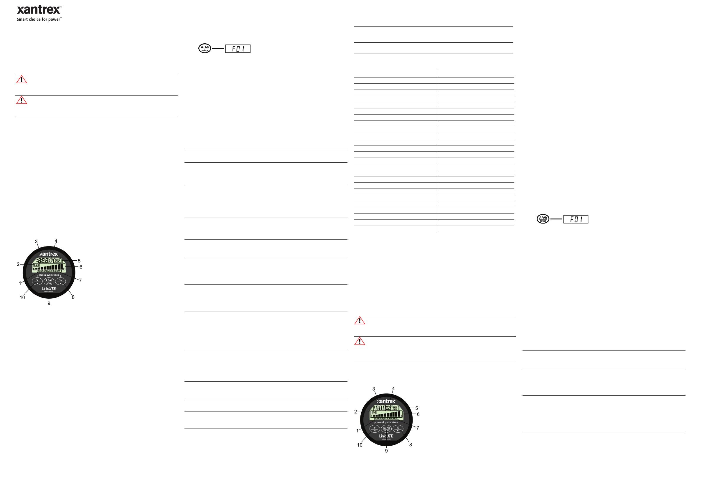
1. Charge battery indicator
2. Alarm activated indicator
3. Numeric value indicator field
4. Readout units
5. Main battery or Auxiliary battery
indicator
6. State-of-charge bar
7. Synchronize indicator
8. Select State-of-charge readout, or next
value (>)
9. Select current(A) or Amphour(Ah)
readout, or enter / leave Setup menu
10. Select voltage readout (Main or
Auxiliary), or previous value (<)
F01
Battery capacity. Your Main battery's capacity in Amphours (Ah).
Default: 200Ah Range: 20 – 999Ah Step size: 1Ah
F02
Charger's float voltage (Auto-sync parameter). This value must be equal to
your battery charger's float voltage. which is the last stage of the charging
process. In this stage the battery is considered full.
Default: 13.2V Range: 8.0V – 33.0V Step size: 0.1V
F03
Charger's float current (Auto-sync parameter). When the charge current is
below this percentage of the battery capacity (see Function F01), the
battery will be considered as fully charged. Make sure this Function value
is always greater than the minimum current at which the charger maintains
the battery or stops charging.
Default: 2.0% Range: 0.5 – 10.0% Step size: 0.1%
F04
Low battery alarm On (% SOC). When the State-of-charge percentage has
fallen below this value, the alarm relay will be activated, the Charge
battery indicator starts flashing and the State-of-charge bar is empty.
Default: 50% Range: 0 – 99% Step size: 1%
F05
Low battery alarm On (Volts). When the battery voltage has fallen below
this value, the alarm relay will be activated.
Default: 10.5V Range: 8.0 – 33.0V Step size: 0.1V
F06
Low battery alarm Off (% SOC). When the State-of-charge percentage has
risen above this value and the alarm relay was activated, the alarm relay
will deactivate again. When "FULL" is selected, the alarm relay is
deactivated when the Auto-sync parameters are met.
Default: 80%
Range: 1 – 100% /FULL
Step size: 1%
F07
Peukert's exponent. The Peukert's exponent represents the effect of
reducing battery capacity at higher discharge rates. When the Peukert
value of your battery is unknown, it is recommended to keep this value at
1.25. A value of 1.00 disables the Peukert compensation.
Default: 1.25 Range: 1.00 – 1.50 Step size: 0.01
F08
Shunt Amp Rating. This Function represents the Amp rating of your shunt
at 50mV. Included with your battery monitor is a 500Amp/50mV shunt,
meaning that at 500A flowing through the shunt, a voltage of 50mV is
generated across the small 'Kelvin' screw terminals of the shunt. This
voltage will be used by the battery monitor to measure the amount of
current.
Default: 500A Range: 10 – 900A Step size: variable
F09
Backlight mode. Represents the duration of backlight activation in seconds
after key-press. The backlight can also be set to be always "ON" or always
"OFF". Function setting "AU", activates the backlight automatically when
charge / discharge current exceeds 1Amp or when a key is pressed.
Default: 30sec Range: OFF / 5 – 300sec
/ ON / AU
Step size: variable
F10
Alarm contact polarity. Enables selection between a normally open (NO)
or normally closed (NC) contact.
Default: NO Range: NO / NC
F11
Reserved
Default: x Range: x
F12
Firmware version. Displays the firmware version of the battery monitor
(read only).
Default: x.xx
[3 sec]
r.b
Reset Battery status. Use this reset item to reset your current battery
status, for example after you have installed a fresh battery of the same
specifications as the previous one.
r.F
Reset Functions. This reset item can be used to reset all Function values
to factory default values.
Parameter LinkLITE
Supply voltage range 9 – 35VDC
Supply current
a
@Vin=24VDC
a. Measured with backlight and alarm relay turned off
7mA
@Vin=12VDC 9mA
Input voltage range (auxiliary battery) 2 – 35VDC
Input voltage range (main battery) 0 – 35VDC
Input current range
b
b. Depends on selected shunt. With standard delivered 500A/50mV shunt (350A continuous), the
range is limited to -600 – +600A.
-999 – +999A
Battery capacity range 20 – 999Ah
Operating temperature range -20 – +50°C
Readout resolution: voltage (0 – 35V) ±0.1V
current (0 – 99A) ±0.1A
current (100 – 999A) ±1A
amphours (0 – 99Ah) ±0.1Ah
amphours (100 – 999Ah) ±1Ah
state-of-charge (0 – 100%) ±1%
Voltage measurement accuracy ±0.3%
Current measurement accuracy ±0.4%
Dimensions: frontpanel ø 64mm (2.54")
body diameter ø 52mm (2.05")
total depth ø 79mm (3.11")
weight 95grams (0.21 lbs")
Shunt dimensions: footprint 45 x 87mm (1.77"x3.43")
(M8 screws) height 17mm (0.67”) (base) / 35mm (1.38”)
weight 145grams (0.32lbs)
Protection class IP20 (frontpanel only IP 65)
Connection Kit # 854-2021-01 (15m, 50 ft)
AVERTISSEMENT : risque d'incendie
N'utiliser cet appareil que s'il a été installé par un installateur qualifié, et
conformément au manuel d'installation.
AVERTISSEMENT :
Les modèles LinkLITE ne sont pas étudiés pour être branchés sur des
appareils de maintien des fonctions vitales ou d’autres équipements ou
appareils médicaux.
1. Indicateur 'Charger la batterie'
2. Indicateur 'Alarme activée
3. Champ indicateur de la valeur numérique
4. Unités relevées
5. Indicateur batterie 'Main' (principale) ou
batterie 'Auxiliary' (auxiliaire)
6. Barre d'état de charge
7. Indicateur 'Synchroniser'
8. Selectionner l'affichage de l'état de charge
de l'afficheur, ou la valeur Suivante (>)
9. Selectionner l'affichage du courant (A) ou
des Ampères heures (Ah), ou entrer / quitter
10. Selectionner l'affichage du voltage
("Main" ou "Auxiliary"), ou la valeur
précédente (<)
F01
Capacité de la batterie. La capacité de votre Batterie est en Ampères heure
(Ah).
Par Défaut : 200Ah Plage : 20 – 999Ah Taille d'étape : 1Ah
F02
Tension float (Entretien) du Chargeur (Paramètre Auto-sync). Cette valeur
doit être égale à la tension float du chargeur de la batterie qui est la
dernière étape du processus de charge. A cette étape, la batterie est
considérée comme pleine.
Par Défaut : 13.2V Plage : 8.0V – 33.0V Taille d'étape : 0.1V
F03
Courant float du Chargeur (Paramètre Auto-sync). Lorsque le courant de
charge est inférieur au pourcentage de capacité de la batterie (voir
Fonction F 5.0), la batterie est considérée comme complètement chargée.
Assurez-vous que cette valeur de Fonction est toujours plus grande que le
courant minimum sur lequel la batterie maintient le chargeur ou arrête de
charger.
Par Défaut : 2.0% Plage : 0.5 – 10.0% Taille d'étape : 0.1%
[3 sec]


