
1510004 - 02092023
SELKIRK CORPORATION
4460 44th Street S.E. Suite F,
Grand Rapids, MI 49512
1-(800)-992-VENT (8368)
www.selkirkcorp.com
Selkirk: U1
PLEASE READ ALL INSTRUCTIONS BEFORE BEGINNING YOUR INSTALLATION. FAILURE TO INSTALL THIS
COMPONENT IN ACCORDANCE WITH ALL INSTRUCTIONS WILL VOID THE CONDITIONS OF CERTIFICATION AND THE
MANUFACTURERS WARRANTY. KEEP THESE INSTRUCTIONS IN A SAFE PLACE FOR FUTURE REFERENCE.
A MAJOR CAUSE OF CHIMNEY-RELATED
FIRES IS FAILURE TO MAINTAIN REQUIRED
CLEARANCES (AIR SPACES) TO
COMBUSTIBLE MATERIALS.
CAUTION!
RISK OF FIRE - DO NOT
install Rubber Boot Flashings in direct contact
with the outside of the chimney, unless the
chimney manufacturer's instructions permit such
direct contact.
LISTED
LISTED
cULus Listed for models:
Selkirk: UT, GT, ST, FC, DT,
JSC, SPR, TLC
Duravent: DT, DP, DVA
Intertek Certified for Model:
Tested / Certified TO:
CAN/ULC-S604
CAN/ULC-S629
UL103 Type HT
The Rubber Boot Flashing Kit is available as an option for passing
through corrugated and metal roofs with the following.
RUBBER BOOT FLASHING
(For Chimney and Direct
Vent Applications)
INSTALLATION
INSTRUCTIONS
SELKIRK CANADA
P.O. Box 526, Depot 1
Hamilton, ON L8L 7X6
1-888-SELKIRK(735-5475)
cscanada@selkirkcorp.com
www.selkirkcorp.ca
DURAVENT INC.
877 Cotting Court
Vacaville, CA 95688
1-800-835-4429
techsupport@duravent.com
www.duravent.com

2
10"
8"
6-5/8"
9"
7"
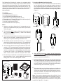
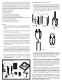
1. One Shield (item 1)
2. Four Spacer Channels (item 2)
3. Three Shield Mounting Brackets (item 3)
4. Twelve #8 x 1/2" sheet metal screws (item 4)
5. Thirty six #9 x 1-1/2” Truegrip GT w/washer wood screws (item 5)
6. One Rubber Boot Flashing (item 6)
7. One roll of mesh screen (item 7)
8. One Universal Storm Collar (item 8)
The Rubber Boot Flashing Kit consists of a ventilated shield
assembly that fits around a pipe section and a rubber boot that
seals around the shield assembly. The shield assembly is first
assembled, installed and supported around the chimney. The
rubber boot is then installed in direct contact with the shield
assembly and sealed to the roof. Install as close to the roof
ridge as possible.
Kit contents:
3.
5.
1.
2.
4.
To install the Rubber Boot Flashing Kit:
Maximum roof pitch allowed for kit is dependent on the
chimney’s outside diameter (OD) as per Table 1 (Roof Pitch
Table) on page 4.
This assembly is NOT a support. Chimney must be supported
with one main support assembly. Refer to the chimney
Installation Instructions.
The air space directly below the roof line must be open and
permit free air circulation. Sealed enclosures around the
chimney are not permitted directly beneath the roof.
The Shield must be mounted so there is a 1” clearance
between the Shield and the wood structure. This establishes
the 2” clearance from the chimney to the wood (Figure 14).
The screws provided for securing the rubber boot to the roof
are #9 x 1-1/2” Truegrip w/washer wood screws and assumes
the rubber boot will be attached through the corrugated roof
and into wood beneath. If the flashing is to be secured only
to a metal roof, 1/4-14 x 1-1/8” Scots/Teks (or equivalent)
sheet metal screws should be acquired and used.
If the Chimney is installed in an area that experiences heavy
snow/ice build-up, it may require additional protection from
sliding snow or ice. See “Snow Splitter” section.
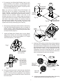
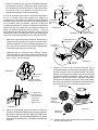
The Shield (item 1) “master” end has a column of master holes
on one edge while the other edge has multiple columns of
holes, designating specific outer diameters of chimney. Form
the Shield into a cylinder by aligning the master holes with the
holes marked for the outer diameter of chimney being installed
(Figure 1).
1.
6.
Item 1
Item 2
Kit Contents:
Item 3
Item 4
Item 6
Item 5
Item 7
Item 8
Fig 3
Fig 4
Fig 1 Fig 2
Master End
When properly formed, the “master” end of the panel will
overlap the marked holes and the Shield will be 2" greater in
diameter than the OD of the pipe. Secure in place with 4 sheet
metal screws (item 4). (See Fig 1).
2.
Install the 4 Spacer Channels (item 2) evenly spaced around
the inside of the shield. Using pliers, bend the channel tabs
over to grip the Shield at both the top and bottom edge. When
correctly installed, each channel will extend beyond the top
and bottom edge of the shield 3/4" (Figure 2).
3.
4.
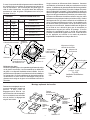
Note: There must be adequate support for the Shield. If roof
decking is already present beneath the corrugated roofing it is
permissible to attach the Shield to it. If such is not the case,
some type of framing will have to be constructed. Three options
are shown in Figures 12, 13 and 14.
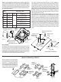
Slide the shield over the chimney and center it within the
prepared roof opening* (Figure 6). Maintain a minimum of 1"
of air space clearance between the Shield and any combus-
tible frame members. This will provide the required 2" of air
space clearance to the chimney.
Notes:

3
Note: If the chimney is installed using a Roof Support the
shield will have to be notched to accommodate the roof
support brackets. To determine the proper notch size and
location, slide the shield down onto the chimney to where it
interferes with the brackets. Based on the size of the
brackets and pitch of the roof, visually gauge the amount of
material that needs to be trimmed in order to allow the shield to
slide down to the proper elevation for mounting. Scribe the
determined cutting pattern onto the shield, remove the shield
from the chimney and trim. This procedure may have to be
repeated until correctly notched (Figures 7a and 7b).
5.
6.
Trim opening of the Rubber Boot Flashing (item 6) to the
proper diameter to fit the Shield. Use the Rubber Boot
Flashing as a guide to position the top of the Shield. Locate
top of the Shield slightly above (approx. 3/4”) the top of the
Rubber Boot Flashing (Figure 5).
* Prior to installing,
construct properly
sized opening.
Top of shield to
be located just
above the top of
the rubber boot
flashing (Approx.
3/4”).
Fig 9
Spacer Tab
extending
through mesh
Spacer tab
flattened
Mesh Screen
Install the Rubber Boot Flashing down over the Shield.
Apply silicone sealant prior to securing the Rubber Boot
Flashing to the roof. Secure to roof using #9 x 1-1/2” Truegrip
wood screws (item 5). See Figure 8.
7.
8. Place the mesh screen (item 7) around the top of the Shield
by carefully impaling it onto the spacer tabs as shown in
Figure 9. Trim any excess as appropriate. Once installed
flatten the spacer tabs to the side of the shield. This will hold
the mesh in place.
Fig 7a
Rubber
washer
Fig 8
Wood
Structure
Silicone Sealant
Support
Bracket
Shield
Notched area
to accommo-
date support
bracket
Fig 7b Support Bracket
mounted to roof
Use third
bracket here
Install the Universal Storm Collar (Figure 10) by wrapping it
around the pipe (extending above the Flashing) until the
desired fit is achieved. Fold the tabs over the excess overlap
to make adjustment easier. Trim any excess as appropriate.
When the Storm Collar has been adjusted to its final
configuration, secure the overlap with two #8 - 1/2” sheet
metal screws (see Figure 10). Orient the Storm Collar so the
seam is towards the low side of the roof slope.
9.
10. Seal the area between the pipe and the Storm Collar using
a high temperature silicone sealant.(See Fig 11).
Fig 5
Fig 6
After properly positioning the Shield, attach it to the framing
using the Shield Mounting Brackets (item 3) oriented as
shown in Figure 6. Attach each bracket to the roof using a
nail (not provided) and to the shield using two sheet metal
screws per bracket (Figure 6).

4
6-5/8"
7"
8"
8"
9"
10" 10/12
UT/ST, JSC/SPR/FC, U1, DT 6"
DT, DVA 5" x 8"
UT/ST, JSC/SPR/FC, U1, DT 7"
UT/ST, JSC/SPR/FC, U1, DT 8", DP6"
DT, DVA 4" x 6-5/8"
UT/ST, JSC/SPR/FC, DT 5"
12/12
2”
2”
8-5/8"
9"
10"
10"
11"
12"
Roof Pitch Table
Table 1
Maximum
Pitch Models / ID
Sheet of plywood with appropriate
sized hole mounted to purlins. (There
must be a 1” airspace clearance
between the shield and the plywood.
On a sloped roof the hole will be
oval in order to achieve the required
clearance at the sloped axis).
Purlins
attached to
trusses
Frame lower
side
of pitched
truss parallel
to Shield.
Fig 14
Purlins
attached to
trusses
Cross slats
attached to
purlins
Sloped
axis
Fig 12 Fig 13
Fig 11
Trim here if
needed
Fig 10
Apply
sealant
here
Note: It is permissible to carefully trim the bottom edge of the
storm collar to achieve a more snug fit around the Rubber Boot
Flashing. On steeper pitched roofs, a portion of the bottom edge of
the Storm Collar (along the up-slope side) will need to be trimmed
to permit collar to slide down upon the rubber boot/shield assem-
bly. (See Figs 10 and 11).
Universal Storm Collar
One fairly common and effective type of Snow Splitter is
described below. Contact local sheet metal fabricators or chim-
ney sweeps for assistance with this or other options. The Snow
Splitter, shown on the right, should be constructed from heavy
gage (minimum 20 gage) galvanized or stainless steel and must
adapt to the pitch of the roof to which it is being installed. Once
installed correctly, the top of the Snow Splitter should be
approximately horizontal and aligned with the center line of the
chimney pipe (see Fig 15A).
The height of the open end of the Snow Splitter should comply
with local code or local area practice methods (see Fig 15B).
Maintain a 2” to 3” gap between the chimney and the Snow
Splitter. Extend the Snow Splitter at least 3” beyond the Flashing
on both sides (see Fig 15A) and at least 6" higher than the cone
of the flashing. Secure the Snow Splitter to the roof using #10 or
heavier screws sufficiently long to insure that the fastener is
adequately secured to the sheathing material. (If no sheathing
is present it may be necessary to include backing material
underneath the roofing). Before tightening the fasteners, apply
silicone or similar weatherproofing sealant under each screw
head.
Fig 15A Fig 15B
Both
sides
Snow Splitter Installation
3”
Per Local Code or Practice
Methods.
Align with center line of
chimney
Adapt to pitch
of roof
Snow Splitter
Approx. 2” to 3”
Center line of
chimney pipe
Options for Mounting of Shield
Snow Splitter
In regions of the country where significant amounts of snow or ice
accumulates, it is recommended that a “Snow Splitter” or similar
device be installed. This is especially important on metal or steep
sloped roofs. A Snow Splitter helps protect the chimney and the
roof flashing from damages caused by sliding snow or ice by
diverting it around the roof flashing and the chimney.
Chimney
OD
Shield
OD
Secure overlap
with two #8-1/2"
Sheet Metal Screws

1
Selkirk: U1
LISEZ TOUTES LES DIRECTIVES AVANT DE PROCÉDER À L'INSTALLATION. À DÉFAUT D'INSTALLER CETTE PIÈCE
SELON CES DIRECTIVES, CECI ANNULERA LES CONDITIONS DE CERTIFICATION AINSI QUE LA GARANTIE DU
FABRICANT. CONSERVEZ CES DIRECTIVES DANS UN ENDROIT SÛR AFIN DE POUVOIR VOUS Y REPORTER, AU
BESOIN.
L'ensemble de solin en caoutchouc est conçu pour rendre étanche
l'installation de cheminées traversant un toit métallique ou
ondulé.
SOLIN EN CAOUTCHOUC
(pour cheminées et évents à
évacuation directe)
DIRECTIVES
D'INSTALLATION
Inscrits / certifiés aux normes:
CAN/ULC-S604
CAN/ULC-S629
UL103 Type HT
HOMOLOGUÉE HOMOLOGUÉE
Pour modèle:
Pour modèles inscrits cULus:
Selkirk: UT, ST, DT, FC, JSC, SPR
Duravent: DT, DP, DVA
UNE DES CAUSES PRINCIPALES D'INCENDIES DE
CHEMINÉES EST LE FAIT DE NE PAS MAINTENIR
LE DÉGAGEMENT REQUIS (ESPACES D'AIR) AUX
MATÉRIAUX COMBUSTIBLES.
ATTENTION!
RISQUE DE FEU - NE PAS INSTALLER le
solin en caoutchouc en contact direct avec
les cheminées, à moins que les directives
d'installation du fabricant de cheminée le
permettent.
1510004 - 02092023
SELKIRK CORPORATION
4460 44th Street S.E. Suite F,
Grand Rapids, MI 49512
1-(800)-992-VENT (8368)
www.selkirkcorp.com
SELKIRK CANADA
P.O. Box 526, Depot 1
Stoney Creek, ON L8L 7X6
1-888-SELKIRK(735-5475)
cscanada@selkirkcorp.com
www.selkirkcorp.ca
DURAVENT INC.
877 Cotting Court
Vacaville, CA 95688
1-800-835-4429
techsupport@duravent.com
www.duravent.com

2
10"
8"
6-5/8"
9"
7"
Contenu de l’ensemble:
1. Bouclier (point 1)
2. Quatre canaux d’entretoise (point 2)
3. Trois supports pour bouclier (point 3)
4. Douze vis de métaux #8 x 1/2 po (point 4)
5. Trente-six vis pour bois Trugrip GT avec anneaux #9 x 1-1/2po (point 5)
6. Solin en caoutchouc (point 6)
7. Un rouleau de tamis à maille (point 7)
8. Collet de solin universel (point 8)
L’ensemble de solin en caoutchouc se compose d’un bouclier
ventilé qui s’ajuste autour d’une section de cheminée et d’un solin
en caoutchouc qui se scelle autour du bouclier. Le montage du
bouclier est d’abord assemblé, installé et soutenu autour de la
cheminée. Le solin en caoutchouc est alors installé en contact
direct avec le bouclier et scellé au toit. Installer plus près du
pignon de toit que possible.
3.
5.
1.
2.
4.
Notes:
La pente maximale de toit pour l’ensemble dépend du diamètre
extérieur de la cheminée. Voir le tableau 1 (tableau de pente
de toit).
Cet ensemble n’est pas un support. La cheminée doit être
soutenue avec un support principal.
Directement au-dessous de la ligne de toit, l'ouverture doit
être complètement ouverte pour permettre une circulation
d’air libre (espace d’air). Les cloisons scellées autour de la
cheminée ne sont pas autorisées directement sous le toit.
Le bouclier doit être monté de sorte qu’il y ait un dégagement
de 1po entre le bouclier et la structure en bois. Ceci établit un
dégagement de 2 po entre la cheminée et la structure de bois
(voir schéma 14).
Utiliser les vis à bois Trugrip GT avec anneaux
#9 x 1-1/2 po pour installer le solin en caoutchouc dans le bois
dessous le toit métallique. Si le solin doit être fixé seulement
au métal, des vis de métal Scots/Teks 1/4-14 x 1-1/8 po (ou
équivalent) devraient être acquises et employées.
Point 1
Point 2
Inclus dans l’ensemble:
Point 6
Point 5
Point 7
Point 8
Point 3
Point 4
L’installation du solin en caoutchouc:
1.
6.Si la cheminée dans un secteur qui éprouve l'abillage
lourd de neige et de glace, il peut exiger une protection
additionnelle contre le glissement. Voir la section
"déflecteur de glace".
Le bout maître du bouclier (point 1) a une colonne de trous
principaux sur un côté tandis que l’autre a des colonnes de
trous, indiquant le diamètre extérieur spécifique de la cheminée.
Former le bouclier en cylindre en alignant les trous principaux
avec les trous marqués pour le diamètre extérieur de la
cheminée étant installée (voir schéma 1).
Schéma 3
Schéma 4
Schéma 1 Schéma 2
Bout maître
Correctement formé, le bout maître du bouclier va recouvrir
les trous marqués et positionnera le bouclier 2 pouces plus
grand que le diamètre extérieur de la cheminée. Fixer en
place avec 4 vis en métal (point 4). Voir le schéma 1.
2.
Installer les 4 canaux d’entretoise (point 2) également
espacée autour de l’intérieur du bouclier. En utilisant des
pinces, pliez les languettes des canaux pour saisir le bouclier
par le rebord supérieur et inférieur. Correctement installé,
chaque canal se prolongera au-delà du rebord supérieur et
inférieur du bouclier 3/4 po (voir le schéma 2).
3.
4.
À noter: Le bouclier doit être supporté adéquatement. Si un toit
de bois est déjà présent, sous la toiture ondulée, il est permis
d’attacher le bouclier à lui. Si tel n’est pas le cas, un certain
type d’encadrement devra être construit. Trois options sont
montrées dans les schémas 12, 13, et 14.
Glissez le bouclier au-dessus de la cheminée et centrez-le
dans l’ouverture déjà préparée du toit (* (voir le schéma 6).
Maintenir un dégagement minimal à 1 po entre le bouclier et
tous matériaux combustibles. Ceci donnera les 2 pouces
exigés de dégagement d’espace d’air à la cheminée.

3
À noter:Si la cheminée doit utiliser un ensemble de support
au toit, le bouclier devra être entaillé pour adapter les
crochets de toit. Pour déterminer la taille et l’endroit approprié
d’entaille, glissez le bouclier vers le bas sur la cheminée jusqu’à
ce qu’il interfère avec les crochets. Baser sur la taille des
crochets et la pente du toit, mesurer visuellement la quantité de
matériel qui doit être entaillé afin de permettre le bouclier de
glissé à la position appropriée pour le montage. Tracez le
motif déterminé de découpage sur le bouclier, soulevez-le de la
cheminée et entaillé. Ce procès peut devoir être répété jusqu’à
ce qu’il soit correctement entaillé (voir les schémas 7a et 7b).
5.
6.
Taillez l’ouverture du solin (point 6) au diamètre approprié
pour adapter le bouclier. Employez le solin comme guide
pour positionner le dessus du bouclier. Positionner le haut
du bouclier pour qu’il dépasse le dessus du solin
approximativement par 3/4 po (voir schéma 5).
Après avoir correctement placé le bouclier, attachez-le au
cadrage avec les supports fournis (point 3) orienté comme
montré au schéma 6. Fixez au toit chaque support avec un
clou (non fourni) et l’autre bout au bouclier à l’aide de deux
vis de métaux par support (voir schéma 6).
Schéma 6
Schéma 5
* Avant d’installer,
préparer l’ouverture.
Fixer le 3ième
support ici.
Le dessus du
bouclier situer
juste au-dessus
du solin en
caoutchouc
(approx. 3/4”).
8.
7. Abaissez le solin en caoutchouc sur le bouclier. Utilisez
un enduit protecteur à la silicone avant de fixer le solin au
toitet. Sécuriser en place au avec les vis pour bois Trugrip
#9 x 1-1/2 po. Voir le schéma 8.
Placez le moustiquaire (schéma 9) autour et dessus le
bouclier en l’embrochant soigneusement sur les languettes
des canaux d’entretoise suivant le schéma 9. Tailler l’excès
comme approprié. Une fois installée aplatissez les canaux
d’entretoise au côté du bouclier. Ceci tiendra le moustiquaire
en place.
Rondelle en
caoutchouc
Enduit protecteur
à la silicone
Schéma 8
Structure
en bois
Schéma 7a
Schéma 7b
Secteur
entaillé pour
adapter au
crochets
Crochet du
support de
toit
Bouclier
Crochet du
support installé
Schéma 9
Repliez les
languettes
Languette
embrocher
dans le
moustiquaire
Moustiquaire
9.
10.
Installez le collet de solin universel (schéma 10) en
l’enveloppant autour de la cheminée (prolonger au-dessus
du solin) jusqu’à ce que l’ajustement désiré soit réalisé.
Repliez les languettes au-dessus du chevauchement
excessif pour faciliter l’ajustement. Tailler l’excès comme
approprié. Une fois que le collet a été ajusté à la position
désirée fixez en place les 2 bouts avec deux vis de métaux
#8 x 12 po (voir schéma 10). Orientez le collet de solin ainsi
que la couture est vers le côté bas de la pente de toit.
Scellez l’espace entre la cheminée et le collet avec de la
silicone. (voir schéma 11).

4
6-5/8"
7"
8"
8"
9"
10" 10/12
UT/ST, JSC/SPR/FC, U1, DT 6"
DT, DVA 5" x 8"
UT/ST, JSC/SPR/FC, U1, DT 7"
UT/ST, JSC/SPR/FC, U1, DT 8", DP6"
DT, DVA 4" x 6-5/8"
UT/ST, JSC/SPR/FC, DT 5"
12/12
2”
2”
8-5/8"
9"
10"
10"
11"
12"
TABLEAU DE PENTE DE TOITTABLEAU 1
Pente
maximale
Appliquer
un silicone
ici
Schéma 10
Schéma 11
Collet de solin universel
À noter: Il est permis de tailler soigneusement le rebord inférieur
du collet de solin pour réaliser un ajustement serré autour du
solin en caoutchouc. Sur les toits ayant une pente aiguë, le
côté du collet faisant face au pignon devra être taillé pour
permettre au collet de glisser complètement au solin (voir
schémas 10 et 11).
Tailler ici si
nécessaire
Modèles / ID
Montage optionnel du bouclier
Panneau de contreplaqué avec une
ouverture appropriée monté aux
pannes. Il doit y avoir un
dégagement d’air libre de 1 po
entre le bouclier et le contreplaqué.
Sur un toit incliné le trou sera ovale
afin de réaliser le dégagement
exigé à l’axe incliné.
Pannes
attachées aux
chevrons
Encadrez le
chevron
inférieur
parallèle au
bouclier.
Schéma 14
Pannes
attachées
aux chevrons
Lattes
attachées
aux
pannes
Axe
incliné
Schéma 12 Schéma 13
Déflecteur de glace
Dans les régions du pays ou les quantités significantes de neige
ou de glace s’accumulent, il est recommandé qu’un déflecteur
de glace ou un dispositif semblable soient installés. Ceci est
particulièrement important si le revêtement du toit est métallique
ou à pente raide. Le rôle d’un déflecteur de glace est de protéger
la cheminée et le solin contre les dommages créés par les
glissements de neige et de glace en les divisant autour de la
cheminée.
Alignez avec la ligne
centrale de cheminée
Adaptez à la
pente de toit
Déflecteur de glace
Approx. 2” à 3”
Chaque
côtés
Schéma
15A
Ligne centrale
de la cheminée
3”
Installation du déflecteur
de glace
Fig 15B
Conforme avec les codes et
pratiques locales.
Un type commun et efficace est décrit ci-dessous. Contacter
un ferblantier ou fabricant de métal pour assistance ou autres
options. Le déflecteur de glace devrait être fait d’acier galvanisé
ou inoxydable de calibre lourd (20) et doit s’adapter à la pente
de toit sur laquelle il est installé. Une fois installé, le dessus du
déflecteur de glace devrait être approximativement horizontal et
aligné avec la ligne centrale de la cheminée (voir schéma 15A).
La hauteur du déflecteur devrait être conforme avec les codes
du bâtiment et les pratiques locales (voir schéma 15B). Gardez
des espaces de 2 à 3 po entre la cheminée et le déflecteur de
glace. Prolongez le déflecteur au moins 3 po au-delà du solin
sur les deux côtés (voire schéma 15A et au moins 6 pouces
plus au que le cone du solin. Attacher le déflecteur de glace au
toit à l’aide de vis à bois #10 (plus gros si nécessaire) et
adéquatement longues pour ancrer au pontage. Si aucun
panneau de contreplaqué existe, il devrait être nécessaire
d’installer un matériel de support sous le toit. Avant de serrer
les vis, appliquez une silicone ou un mastic de protection
imperméable semblable sous chaque tête de vis.
D.E.
Cheminée
D.E.
Bouclier
Fixez les bouts
ensemble avec 2 vis
de métaux #8-1/2"
-
 1
1
-
 2
2
-
 3
3
-
 4
4
-
 5
5
-
 6
6
-
 7
7
-
 8
8


DuraVent DuraTech 5"-8" Guide d'installation
- Taper
- Guide d'installation
- Ce manuel convient également à
dans d''autres langues
Documents connexes
Autres documents
-
HeatStar 9050360 Le manuel du propriétaire
-
Continental Fireplaces CB46NTREA Guide d'installation
-
 Regency Fireplace Products Alterra CS2400 Le manuel du propriétaire
-
-
NAPOLEON Plazmafire 48 Le manuel du propriétaire
-
-
-
-
-
