Dyna-Glo Dyna-Glo EG7500DGP 7500W Electric Garage Heater Manuel utilisateur
- Catégorie
- Chauffe-eau
- Taper
- Manuel utilisateur
Ce manuel convient également à

Before the rst use of this heater, please read this USER’S MANUAL
very carefully. This USER’S MANUAL has been designed to instruct
you as to the proper manner in which to assemble, maintain, store,
and most importantly, how to operate the heater in a safe and efcient
manner. Please keep this manual for future reference.
CONSUMER: Retain this manual for future reference.
Questions, problems, missing parts? Before returning to your retailer, call our customer
service department at 877-447-4768 8:00 a.m. - 4:30 pm CST, Monday - Friday.
or email us at [email protected]
IMEG7500DGP-NKA
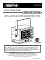
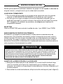
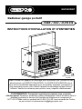
Electric Garage Heater
INSTALLATION & MAINTENANCE INSTRUCTIONS
CSA C22.2 No. 46-13
UL 2021
7,500W / 240V / 25,590 BTU
EG7500DGP

IMPORTANT INSTRUCTIONS
This Product can expose you to chemicals including Diisononyl phthalate (DINP) which is known
to the State of California to cause cancer and Di-isodecyl phthalates (DIDP) which is known to the
State of California to cause birth defects or other reproductive harm.
For more information go to www.p65Warnings.ca.gov
WARNING
2
PET OWNERS WARNING: The health of some small pets including birds are extremely
sensitive to the fumes produced during the rst-time use of many appliances. These fumes are
not harmful to humans but we recommended that you do not use your heater around birds and
small pets during its initial use until the manufacturing protective coatings burn off.
THIS HEATER REQUIRES HARDWIRE INSTALLATION (NO PLUG). THE
INSTALLATION OF THIS PRODUCT MUST BE CARRIED OUT BY A CERTIFIED
ELECTRICIAN AND IN ACCORDANCE WITH ALL LOCAL AND NATIONAL
ELECTRICAL CODES.
When using electrical appliances, basic precautions should always be followed to reduce the
risk of re, electric shock, and injury to persons, including the following:
1. Read all instructions before installing or using this heater.
2. This heater is hot when in use. To avoid burns, do not let bare skin touch hot
surfaces. Keep combustible materials, such as electrical cords, furniture, pillows,
bedding, papers, clothes, and curtains at least 3 feet (0.9 m) from the front of the
heater and keep them away from the sides and rear.
3. Extreme caution is necessary when any heater is used by or near children or
invalids and whenever the heater is left operating and unattended.
4. Always turn off the power to the heater when not in use.
5. Do not operate any heater after the heater malfunctions, has been dropped or
damaged in any manner. Disconnect power at the service panel and have the
heater inspected by a reputable electrician before reusing.
6. Do not use outdoors.
7. This heater is not intended for use in bathrooms, laundry areas and similar indoor
locations. Never locate heater where it may fall into a bathtub or other water
container.
8. Do not insert or allow foreign objects to enter any ventilation or exhaust opening as
this may cause an electric shock or re, or damage the heater.
9. To prevent a possible re, do not block air intakes or exhaust in any manner. Do not
use on soft surfaces, like a bed, where openings may become blocked.
10. A heater has hot and arcing or sparking parts inside. Do not use it in areas where
gasoline, paint, or ammable liquids are used or stored.
11. Use this heater only as described in this manual. Any other use not recommended
by the manufacturer may cause re, electric shock, or injury to persons.
12. To disconnect heater, turn controls to off, and turn off power to heater circuit at main
disconnect panel.
13. If the red alarm light on the front of the unit illuminates, immediately turn the heater
off and inspect for any objects on or adjacent to the heater that may have blocked
the airow or otherwise caused high temperaturs to have occurred. DO NOT
OPERATE THE HEATER WITH THE ALARM LIGHT ILLUMINATING.
SAVE THESE INSTRUCTIONS

3
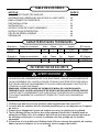
ITEM PAGE #
SPECIFICATIONS ........................................................................... 3
SAFETY INFORMATION ................................................................. 3
LOCATING HEATER ....................................................................... 4
PRE-INSTALLATION ....................................................................... 5
INSTALLATION ............................................................................... 6
OPERATING INSTRUCTIONS ........................................................ 10
MAINTENANCE .............................................................................. 12
REPLACEMENT PARTS ................................................................. 12
TROUBLESHOOTING .................................................................... 13
1. Use only copper wires rated for at least 60ºC.
2. Heater air ow must be directed parallel to or away from adjacent wall.
3. Observe all wall, oor and ceiling clearance requirements.
4. All wiring must be done according to national and local electrical codes. The
heater must be grounded as a precaution against possible electrical shock.
Heater circuit must be protected with proper fuses.
5. The mounting structure and the anchoring hardware must be capable of
supporting the weight of the heater and the mounting bracket (if used).
TABLE OF CONTENTS
SPECIFICATIONS
SAFETY INFORMATION
THIS HEATER REQUIRES HARDWIRE INSTALLATION (NO PLUG). THE INSTALLATION OF THIS
PRODUCT MUST BE CARRIED OUT BY A CERTIFIED ELECTRICIAN AND IN ACCORDANCE WITH
ALL LOCAL AND NATIONAL ELECTRICAL CODES.
NOTE: COMPATIBLE WITH A 240V LINE VOLTAGE DOUBLE POLE WALL THERMOSTAT. MUST BE
INSTALLED BY A CERTIFIED ELECTRICIAN.
READ AND UNDERSTAND ALL INSTALLATION & OPERATION INSTRUCTIONS PRIOR TO
OPERATING THIS UNIT. OBSERVE ALL SAFETY INSTRUCTIONS.
WARNING
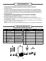
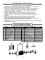
Rating Switch Setting Volts Phase Hz AMPS BTU/hour
7500W II 240 160 31.25 22590
5000W I 240 160 20.9 17060
Rating Switch Setting Volts Phase Hz AMPS BTU/hour
5600W II 208 160 26.9 19107
3700W I 208 160 17.9 12625

4
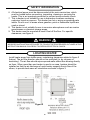
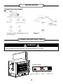
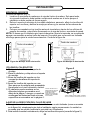
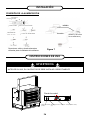
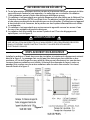
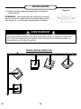
Install heater away from trafc areas, maintaining clearances stated in gure 2
(below). The air ow direction should not be restricted (ie. by columns or
machinery). The air ow should wipe exposed walls rather than blowing directly
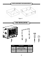
on them. When more than one heater is used in an area, heaters should be
installed so that the air discharge of each heater supports the air ow of the
others, to provide best warm air circulation as shown in gure 3.
Figure 2
SAFETY INFORMATION
LOCATING HEATER
IMPROPER INSTALLATION OR FAILURE TO FOLLOW THE PROCEDURES OUTLINED IN THIS
INSTRUCTION MANUAL CAN RESULT IN SERIOUS ELECTRICAL SHOCK.
WARNING
6. All electrical power must be disconnected at the main service box, which
must be locked before connecting, inspecting, cleaning or servicing the
heater. This is an important precaution to prevent serious electric shock.
7. This is heater is not suitable for use in hazardous locations containing
explosive liquids or vapours. This heater has hot or arcing or sparking parts
inside. Do not use it in areas where gasoline, paint or ammable liquids are
used or stored.
8. This heater is not suitable for use in corrosive atmospheres such as marine
greenhouses or chemical storage areas.
9. This heater must be mounted at least 8 feet off the oor. For specic
clearances, see gure 2.
FOR:

5
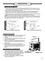
Part Description Quantity
A Garage Heater 1
BMounting Bracket 1
C Screw 3
D Washer 6
PRE-INSTALLATION
LOCATING HEATER
Figure 3

6
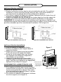
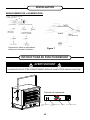
Wood Ceiling Wood Ceiling
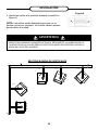
MOUNTING THE BRACKET
Refer to Figures 4a and 4b.
1. Locate a wood stud in the wood ceiling joist/side wall. For ceiling only, if you
cannot locate a wood stud, you have to install a wood piece on the ceiling as
this heater must be securely fastened.
2. Remove the mounting bracket from the heating unit by loosening bracket
screws with a wrench and slipping the handle off over the screw heads.
3. Place a washer on screws before inserting through the holes in the mounting
bracket and screw them securely into a ceiling joist or wall stud.
NOTE: If you want to swivel the heater either to the right or left adding a washer
to both sides of the bracket is recommended. A longer lag bolt may be required
to properly secure the unit. See Figure 4a.
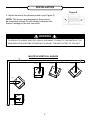
Figure 5
Figure 4a. Single-Screw Mounting Figure 4b. Double-Screw Mounting
INSTALLATION
Side Wall
Side Wall
ADJUSTING AIR FLOW DIRECTION
1. To turn the unit when it has been installed
with a single lag bolt (as shown in gure
4a), simply turn the entire heater as needed.
The unit cannot be turned horizontally if it
has been installed with 2 lag bolts.
2. To tilt the unit vertically, loosen the bracket
screws (see gure 5).
HANGING THE HEATER
1. Attach the heating unit to the mounting bracket.
2. Lift the heater up and into the mounting
bracket.
3. Align the bracket screws with the keyhole slots
in the mounting bracket.
4. Tighten the bracket screws with a wrench so
the unit is securely suspended at horizontal or
vertical level.
5. The heater can be mounted with different
angles listed in the drawing on page 7 as long
as you maintain proper clearance listed on
page 4.
LOOSEN KNOBS AND SELECT MOUNTING
HOLE BASED ON DESIRED HEATER ANGLE.
REFER TO DIAGRAM ON PAGE 7.

6 7
MULTIPLE VERTICAL ANGLES
3. Adjust louvers to the desired position (see Figure 6).
NOTE: The louvers are designed so they cannot
be completely closed. Do not attempt to bypass this
feature; damage to the unit can result.
CEILING
90 degrees
90 degrees
seerged 54seerged 5.76
45 degrees
INSTALLATION
Figure 6
TO PREVENT POSSIBLE ELECTRIC SHOCK, DISCONNECT POWER TO THE HEATER AT THE
MAIN SERVICE BOX BEFORE ATTEMPTING TO ADJUST THE HEAT OUTPUT OF THIS UNIT.
WARNING

8
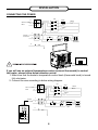
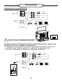
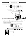
CONNECTING THE POWER
INSTALLATION
2500W
2500W
2500W
Switch
KM
KM
1
2
L1
L2
240AC or 208AC
60HZ
External
thermostat
GND
E
Selected
switch
Heater's
thermostat
2500W
2500W
2500W
Switch
KM
KM
1
2
L1
L2
240AC or 208AC
60HZ
External
thermostat
3
4
LINE
RED
LOAD
BLACK
External thermostat
Terminal station
1
2
GND
E
Selected
switch
Heater's
thermostat
Selection Switch
(Heater’s thermostat, External thermostat)
Heater’s
thermostat
External
thermostat
If you will use an external temperature control (external thermostat) to control
the heater, please follow below attention points:
1. Make sure that the heater's temperature control knob (thermostat knob) is turned
fully clockwise.
2. Connect the wire according to below wiring diagram.

9
INSTALLATION
3. Connect the wire to the power block located in the base of the heater - See
Figure 7.
4. Turn on the power at the main service.
NOTE: All wiring must be carried out by a Certied Electrician and must be in
accordance to national and local electrical codes. For certain applications, conduit
may be required, See Figure 7. Check local electrical codes. If you run the wiring in
conduit and wish to be able to turn the heater be sure to purchase enough exible
conduit to allow the heater to be turned.
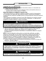
HIGH TEMPERATURES – RISK OF FIRE. KEEP FLAMMABLE MATERIALS, SUCH AS
FURNITURE, PILLOWS, BEDDING, PAPERS, CLOTHES, ELECTRICAL CORDS AND CURTAINS
AT LEAST 3 FT. (0.9 M) FROM THE FRONT AND TOP OF THE HEATER AND KEEP THEM AWAY
FROM THE SIDES AND REAR. TO REDUCE THE RISK OF FIRE, DO NOT USE IT IN AREAS
WHERE GASOLINE, PAINT OR FLAMMABLE LIQUIDS ARE USED OR STORED.
WARNING
TO REDUCE THE RISK OF FIRE, DO NOT STORE OR USE GASOLINE OR OTHER
FLAMMABLE VAPORS AND LIQUIDS IN THE VICINITY OF THE HEATER.
WARNING
CONNECTING THE POWER
3. The external temperature control (external thermostat): a certied thermostat
must be used.
4. The lead wire of external temperature control (external thermostat) can not
be less than 14AWG.
TO PROTECT THE HEATING ELEMENT
When starting the heater, turning the temperature control clockwise slowly to desired
heat setting, the unit starts the fan rst then starts the heating element.
When shutting off the heater, turning the temperature control counter-clockwise to off,
both the fan and the heating element turn off at the same time.
THIS APPLIANCE MUST BE GROUNDED!
THE APPLIANCE MUST CONNECT TO A CURRENT PROTECTION CIRCUIT OR DEVICE
BEFORE BEING CONNECTED TO POWER SUPPLY!
WARNING
1. Remove the screw from the front of the unit to connect the power to the heater.
2. Attach the cable connectors to the unit (See Figure 7). Select power supply
wire to comply with local and national electric codes using heater rating given
on the rating label.

10
CONNECTING THE POWER
Connectors, cable, and hardware used to
wire the heater Figure 7
Conduit
Connector
Conduit
Flexible Conduit
Flexible NM Cable Flexible NM Cable Connector
Flexible Conduit Connector
WHITE
BLACK
GREEN
(or bare copper)
3ft
INSTALLATION
OPERATING INSTRUCTIONS
THE HEATER MUST BE PROPERLY INSTALLED BEFORE IT IS USED.
WARNING
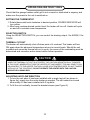
7500W 5000W
Control Panel
Power Indicator
(Yellow)
Caution Indicator
(Red)
Thermostat Switch (5000W / 7500W)

11
Check that the garage heaters outlet grill is not covered or obstructed in anyway, and
make sure the power to the unit is switched on.
SETTING THE THERMOSTAT
1. Rotate thermostat knob clockwise to desired position, POWER INDICATOR will
turn yellow.
2. After room reaches desired comfort level the heater will turn off. Heater will cycle
on and off to maintain room temperature.
SELECTION SWITCH
Using the SELECTION SWITCH, you can control the heating output: I for 5600W, II for
7500W
THERMAL CUT-OUT
The heater will automatically shut off when parts of it overheat. The heater will turn
ON again when the abnormal temperature returns to normal levels. Should the unit
overheat and cause the thermal cut-out to cycle, the cause of the overheating must be
determined and corrective action taken before further operation.
OPERATING INSTRUCTIONS
ADJUSTING AIR FLOW DIRECTION
1. To turn the unit when it has been installed with a single lag bolt (as shown in
gure 4a), simply turn the entire heater as needed. The unit cannot be turned
horizontally if it has been installed with 2 lag bolts.
2. To tilt the unit vertically, loosen the bracket screws (see Figure 5).
WHEN THE THERMAL CUT-OUT IS ACTIVATED, THE CAUTION INDICATOR WILL TURN RED.
IN THIS CASE, IMMEDIATELY TURN THE HEATER OFF AND INSPECT FOR ANY OBJECTS ON
OR ADJACENT TO THE HEATER THAT MAY CAUSE HIGH TEMPERATURES. DO NOT TAMPER
WITH ANY OF THE CONTROLS. DO NOT OPERATE THE HEATER WITH THE CAUTION
INDICATOR GLOWING RED.
CAUTION

12
1. Before cleaning, make sure the power has been turned off at the circuit breaker
panel and that the heating element of the heater is cool.
2. To maintain the external appearance of the heater, the unit occasionally needs to
be wiped with a dry duster. During the summer months, or at other times when
the appliance is not in use and is completely cold, it should be the wiped over
with a damp cloth.
3. Do not use abrasive cleaning powders or furniture polish. Do not use chemical or
abrasive products, metallic scourers and so on, which may deteriorate the sur-
face, to clean the appliance.
4. During the summer months, or at other times when the appliance is not in use,
disconnect the power supply. Keep the appliance in a dry and cool place.
5. All other servicing should be performed by qualied service personnel. Do not try
to repair the heater yourself.
NOTE: The motor is permanently lubricated, and no further lubrication is needed.
MAINTENANCE
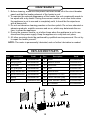
REPLACEMENT PARTS
Part Description Part#
1Back mesh EG5000001AC
2Hanging plate EG5000002AC
3 Fan Blade EG5000003AC
4Air guide plate EG5000004AC
5Large handle seat EG5000005AC
6Small handle seat EG5000006AC
7Spring EG5000007AC
8Motor
EG5000008AC-DGC
Part Description Part#
9 Heater EG7500001AC
10 Selection Switch EG5000011AC
11 Thermostat EG5000012AC
12 Knob EG5000013AC
13 Terminal block
EG5000014AC-DGC
14 Temperature CUT-OFF EG5000017AC
15 Caution Indicator (Red) EG5000018AC
16 Power Indicator (Yellow) EG5000019AC
17 AC Contactor EG7500002AC

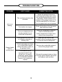
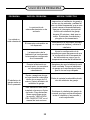
TROUBLESHOOTING
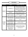
PROBLEM ROOT CAUSE CORRECTIVE ACTION
Unit is not
heating.
The overheat protection has
activated.
Inspect the garage heater and
check that the air inlets and outlets
are not blocked as this may cause
overheating. Switch off the circuit
breaker to the garage heater for 30
minutes and allow it to cool down.
Turn the power back on and operate.
The breaker has tripped Reset the breaker at the fuse panel
and restart the heater
The room temperature has
already reached the set
thermostat temperature
Adjust the temperature setting to
make sure the thermostat
setting temperature is higher than
current room temperature.
Garage heater
emits a
burning smell
During production dust and/
or oil debris gathered on
heating coils.
Make sure the room is well
ventilated. Allow the garage heater to
run until the smell is dissipated.
Check and make sure there
is no combustible material
within 0.9 meters (3 feet) of
the garage heater.
Remove the combustible material
around the garage heater.
This heater must be
mounted at least 8 feet
off the oor, for specic
clearances, please check
the "LOCATING HEATER"
section in the instruction
manual
Relocate the garage heater so there
is enough space between the heater
and adjacent wall and oor.
13

PRODUCT NOTES

Warranty
LIMITED WARRANTY:
This limited warranty is extended to the original retail purchaser of this Forced Air/Convection/Radiant Heater and warrants against any defect
in materials and workmanship for a period of one (1) year from the date of retail sale.GHP Group, Inc., at it’s option, will either provide
replacement parts or replace or repair the unit, when properly returned to the retailer where purchased or one of our service centers
as directed by GHP Group,Inc., within one (1) year of retail purchase. (Shipping costs, labour costs,etc. are the responsibility of the purchaser.)
DUTIES OF THE OWNER:
This heating appliance must be operated in accordance with the written instructions furnished with this heater. This warranty shall not excuse
the owner from properly maintaining this heater in accordance with the written instructions furnished with this heater. A bill of sale, canceled
check or payment record must be kept to verify purchase data and establish warranty period. Original carton should be kept in case of
warranty return of unit.
WHAT IS NOT COVERED:
1. Damage resulting from use of improper fuel.
2. Damage caused by misuse or use contrary to the owners manual and safety guidelines.
3. Damage caused by a lack of normal maintenance.
4. Fuses
5. Use of non-standard parts or accessories.
6. Damage caused in transit. Freight charges on warranty parts or heaters to and from the factory shall be the responsibility of the owner.
This warranty does not imply or assume any responsibility for consequential damages that may result from the use, misuse, or the lack of
routine maintenance of this heating appliance. A cleaning fee and the cost of parts may be charged for appliance failures resulting from lack of
maintenance. This warranty does not cover claims which do not involve defective workmanship or materials. FAILURE TO PERFORM
GENERAL MAINTENANCE (INCLUDING CLEANING) WILL VOID THIS WARRANTY.
THIS LIMITED WARRANTY IS GIVEN TO THE PURCHASER IN LIEU OF ALL OTHER WARRANTIES, EXPRESSED OR IMPLIED,
INCLUDING BUT NOT LIMITED TO THE WARRANTIES OF MERCHANTABILITY OF FITNESS FOR A PARTICULAR PURPOSE. THE
REMEDY PROVIDED IN THIS WARRANTY IS EXCLUSIVE AND IS GRANTED IN LIEU OF ALL OTHER REMEDIES. IN NO EVENT
WILL GHP GROUP, INC. BE LIABLE FOR INCIDENTAL OR CONSEQUENTIAL DAMAGES.
Some states do not allow limitations on how long an implied warranty lasts, so the above limitation may not apply to you. Some states do not
allow the exclusion or limitation of incidental or consequential damages so the above limitation or exclusion may not apply to you.
CLAIMS HANDLED AS FOLLOWS:
1. Contact your retailer and explain the problem.
2. If the retailer is unable to resolve the problem, contact our Customer Service Dept. detailing the heater model, the problem, and proof
of date of purchase.
3. A representative will contact you. DO NOT RETURN THE HEATER TO GHP GROUP, INC. unless instructed by our Representative.
This warranty gives you specic legal rights and you may also have other rights which vary from state to state.
TO REGISTER THE WARRANTY ON YOUR HEATER, PLEASE FILL OUT THIS CARD COMPLETELY
AND MAIL WITHIN 14 DAYS FROM DATE OF PURCHASE OR REGISTER ON-LINE AT www.ghpgroupinc.com
NAME: _______________________________ PHONE: ( ) _________________ EMAIL: ____________________________________
ADDRESS: ___________________________ CITY: ________________________ STATE: _____________________ ZIP: ___________
MODEL: ______________________________ SERIAL#: _____________________ DATE PURCHASED: _________________________
DEALER PURCHASED FROM: _________________________________________ TYPE OF STORE: __________________________
CITY & STATE WHERE PURCHASED: ___________________________________ PRICE PAID: _______________________________
Please Take 1 Minute To Give Us Your Answers To The Following Questions.
All Responses Used Solely For Market Research And Are Held In Strict Condence.
Who primarily decided this purchase? Male Female 18-24 25-39 40-59 60 and over of age?
Do you own any other portable heaters? Yes No If yes, type ______________________ brand ____________________________
How do you intend to use your new heater? Construction Site Farm Warehouse/Commercial Garage/Outbuilding Other
How did you become aware of this heater? In-Store Display Newspaper Ad Magazine Ad Friend/Relative
TV Commercial Store Salesperson Other ____________________________________________________________________
What made you select this heater? Style Size/Portability Price Package Brand Other __________________________
Do you: Own Rent Would you recommend this heater to a friend? Yes No
Please give us your comments _____________________________________________________________________________________
THANK YOU FOR COMPLETING THIS FORM!
Information will be held condential.

WARRANTY REGISTRATION
IMPORTANT: We urge you to ll out your warranty registration card within fourteen (14)
days of date of purchase. You can also register your warranty on the internet at
www.ghpgroupinc.com. Complete the entire serial number. Retain this portion of the card
for your records.
Place
Postage
Stamp
Here
SAVE THIS CARD!
GHP Group, Inc.
6440 W Howard St
Niles, IL 60714-3302
Tel: (877) 447-4768
www.ghpgroupinc.com
GHP Group, Inc.
6440 W Howard St
Niles, IL 60714-3302

Antes de utilizar por primera vez este calentador, lea este MANUAL DEL
USUARIO atentamente. Este MANUAL DEL USUARIO ha sido diseñado
para instruirle la forma adecuada de ensamblar el calentador, brindarle
mantenimiento, guardarlo y lo más importante: cómo hacerlo funcionar de
manera segura y ecaz. Conserve este manual para referencia futura.
CONSUMIDOR: Conserve este manual para referencia futura.
¿Preguntas, problemas, partes faltantes? Antes de regresar al distribuidor,
llame a nuestro departamento de servicio al 877-447-4768 de 8:00 a.m. a
4:30 p.m. hora estándar del centro, de lunes a viernes o envíenos un correo
electrónico a [email protected].
Calefactor de garaje eléctrico
INSTRUCCIONES DE INSTALACIÓN Y MANTENIMIENTO
7,500W / 240V / 25,590 BTU
CSA C22.2 No. 46-13
UL 2021
EG7500DGP

18
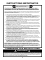
ADVERTENCIA PARA DUEÑOS DE MASCOTAS: Algunas mascotas pequeñas, incluidos los
pájaros, son muy sensibles a la exposición de los humos que se producen durante el uso de
electrodomésticos por primera vez. Estos humos no son dañinos para los seres humanos, pero
le recomendamos que no utilice el calefactor cerca de pájaros y mascotas pequeñas durante el
primer uso de la unidad hasta que los recubrimientos anticorrosivos se quemen por completo.
INSTRUCCIONES IMPORTANTES
GUARDE ESTAS INSTRUCCIONES
Este producto puede exponerlo a usted a agentes químicos incluyendo ftalato de diisononilo
(DINP), reconocido por el estado de California como causante de cáncer, así como ftalatos de
diisodecilo (DIDP), reconocidos por el estado de California como causantes de defectos congénitos
y otros daños al sistema reproductor.
Para obtener más información, visite www.p65Warnings.ca.gov
ADVERTENCIA
ESTE CALEFACTOR REQUIERE INSTALACIÓN CABLEADA (SIN ENCHUFE). LA
INSTALACIÓN DE ESTE PRODUCTO DEBE REALIZARLA UN ELECTRICISTA
CERTIFICADO EN CONFORMIDAD CON TODOS LOS CÓDIGOS ELÉCTRICOS LOCALES
Y NACIONALES.
Al usar electrodomésticos, siempre se deben respetar las precauciones básicas para reducir el
riesgo de incendio, choques eléctricos y lesiones personales, incluidas las siguientes:
1. Lea todas las instrucciones antes de instalar o usar este calefactor.
2. Este calefactor se calienta cuando está en uso. Para evitar quemaduras, no toque las
supercies calientes con la piel descubierta. Mantenga los materiales combustibles, como
cable eléctricos, muebles, almohadas, ropa de cama, papeles, vestimenta, cortinas, etc. a
una distancia mínima de 3 pies (0,90 m) de la parte frontal del calefactor, y alejados de los
laterales y de la parte trasera.
3. Se debe tener sumo cuidado al usar calefactores junto a niños o personas inválidas, o
cerca de ellos, y en todo momento en que el calefactor se deje prendido y desatendido.
4. Siempre desconecte la alimentación al calefactor cuando no esté en uso.
5. No ponga en funcionamiento ningún calefactor después de que haya fallado. Desconecte
la energía en el panel de servicio y haga que un electricista acreditado inspeccione el
calentador antes de reutilizarlo.
6. No lo utilice al aire libre.
7. Este calefactor no está diseñado para usarse en baños, lavaderos o lugares cubiertos
similares. No ubique el calefactor en un lugar donde pueda caerse dentro de una bañera u
otro contenedor de agua.
8. No inserte ni permita que ingresen objetos extraños en ninguna abertura de ventilación o
escape porque podrían provocar un choque eléctrico, un incendio o daños en el calefactor.
9. Para evitar posibles incendios, no bloquee las tomas de aire ni el conducto de escape de
ninguna manera. No haga funcionar el calefactor sobre supercies blandas, como una
cama, donde las aberturas puedan bloquearse.
10. El calefactor contiene piezas internas que se calientan, forman arcos eléctricos o generan
chispas. No lo use en áreas donde se utilice o se guarde gasolina, pintura o líquidos
inamables.
11. Utilice este calefactor solo como se describe en este manual. Otros usos no
recomendados por el fabricante podrían provocar incendios, choques eléctricos o lesiones
personales.
12. Para desconectar el calentador, apague los controles y apague el circuito del calentador
en el panel de desconexión principal.
13. Si se enciende la luz roja de alarma en la parte frontal de la unidad, apague
inmediatamente el calentador e inspeccione si hay objetos en el calentador o adyacentes
al mismo que puedan haber bloqueado el ujo de aire o haber causado altas temperaturas.
NO OPERE EL CALENTADOR CON LA LUZ DE ALARMA ILUMINADA.

19
ARTÍCULO PÁGINA
ESPECIFICACIONES ..................................................................... 19
INFORMACIÓN GENERAL SOBRE SEGURIDAD ......................... 19
UBICACIÓN DEL CALEFACTOR .................................................... 20
PRE-INSTALACIÓN ........................................................................ 21
INSTALACIÓN ................................................................................. 22
INSTRUCCIONES DE USO ............................................................ 26
MANTENIMIENTO Y LIMPIEZA ..................................................... 28
PIEZAS DE REPUESTO ................................................................. 28
SOLUCIÓN DE PROBLEMAS ........................................................ 29
1. Utilice solo cables de cobre calicados para 60°C como mínimo.
2. El ujo de aire del calefactor se debe orientar de modo que quede paralelo a la
pared adyacente o en dirección contraria a ella.
3. Respete los requisitos de espacio libre hacia la pared, el piso y el techo.
4. Todo el cableado se debe realizar de conformidad con los códigos nacionales y
locales de electricidad de Estados Unidos y el calefactor debe estar conectado
a tierra como precaución contra posibles choques eléctricos. El circuito del
calefactor se debe proteger con fusibles apropiados.
5. La estructura de montaje y la tornillería de anclaje deben poder soportar de modo
conable el peso del calefactor y del soporte de montaje, si se lo utiliza.
CONTENIDO
ESPECIFICACIONES
INFORMACIÓN SOBRE SEGURIDAD
ESTE CALEFACTOR REQUIERE UNA INSTALACIÓN CABLEADA FIJA (SIN ENCHUFE). A LA
INSTALACIÓN LA DEBE REALIZAR UN ELECTRICISTA CERTIFICADO Y SE DEBE EFECTUAR
DE CONFORMIDAD CON TODOS LOS CÓDIGOS LOCALES Y NACIONALES DE ELECTRICIDAD.
NOTA: COMPATIBLE CON UN TERMOSTATO DE PARED BIPOLAR CON TENSIÓN DE LÍNEA DE
240 V. DEBE SER INSTALADO POR UN ELECTRICISTA CERTIFICADO.
LEA Y COMPRENDA TODAS LAS INSTRUCCIONES DE INSTALACIÓN Y FUNCIONAMIENTO, Y
RESPETE TODAS LAS INSTRUCCIONES DE SEGURIDAD.
ADVERTENCIA
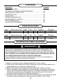
Índice
Conguración del interruptor
Voltios Fase Hz Amperios BTU/hora
7500W II 240 160 31.25 22590
5000W I 240 160 20.9 17060
Índice
Conguración del interruptor
Voltios Fase Hz Amperios BTU/hora
5600W II 208 160 26.9 19107
3700W I 208 160 17.9 12625

20
DISTANCIA
MÍNIMA
A PARED
DISTANCIA
MÍNIMA
A PARED
13 pulg.
10-⁄ pulg.
24 pulg.
4½ pulg.
¾ pulg.
1¾ pulg.
½ pulg.
7-3/8 pulg.
4½ pulg.
DISTANCIA
MÍNIMA
DESDE LA
DESCARGA A
UN OBJETO
DISTANCIA
MÍNIMA AL PISO
8 pies
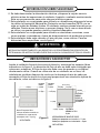
ALTURA MÁXIMA DE MONTAJE DESDE:
Unidad para proporcionar aire vertical = 11 pies
Unidad para proporcionar aire horizontal = 8 pies
Nota: El espacio libre
mínimo al techo cuando no
se utilizan los soportes de
montaje es de 1-⁄ pulg.
14 pulg.
12½ pulg.
VISTA FRONTAL Figura 2
Instale el calefactor fuera de las zonas de tránsito y mantenga los espacios libres
indicados en la gura 2. La dirección del ujo de aire no debe estar restringida por
columnas o máquinas. El ujo de aire solo debe rozar las paredes y no dirigirse
directamente a ellas. Cuando se utiliza más de un calefactor en un área, los
calefactores se deben disponer de modo que la descarga de aire de cada uno
acompañe el ujo de aire de los otros para proporcionar una circulación óptima de
aire caliente, como se indica en la gura 3.
INSTALAR INCORRECTAMENTE O NO RESPETAR LOS PROCEDIMIENTOS DESCRITOS EN
ESTE MANUAL DE INSTRUCCIONES PUEDE DAR LUGAR A CHOQUES ELÉCTRICOS GRAVES.
ADVERTENCIA
INFORMACIÓN SOBRE SEGURIDAD
UBICACIÓN DEL CALEFACTOR
VISTA LATERAL
6. Se debe desconectar la alimentación eléctrica y bloquear la caja de servicio
eléctrico antes de inspeccionar el calefactor, limpiarlo o realizarle mantenimiento.
Esta es una precaución para evitar choques eléctricos graves.
7. Este calefactor no es apropiado para utilizarlo en ubicaciones peligrosas tal como
las dene la Asociación Nacional de Protección contra Incendios (NFPA, por su
sigla en inglés) de Estados Unidos. El calefactor contiene piezas internas que se
calientan, forman arcos eléctricos o generan chispas. No lo use en áreas donde
se utilice o se guarde gasolina, pintura o líquidos inamables.
8. Este calefactor no es apropiado para utilizarlo en atmósferas corrosivas, como
zonas marinas, invernaderos o áreas de almacenamiento de productos químicos.
9. Este calefactor debe estar ubicado a 8 pies del piso, como mínimo. Para las
distancias libres especícas, vea la gura 2.
La page charge ...
La page charge ...
La page charge ...
La page charge ...
La page charge ...
La page charge ...
La page charge ...
La page charge ...
La page charge ...
La page charge ...
La page charge ...
La page charge ...
La page charge ...
La page charge ...
La page charge ...
La page charge ...
La page charge ...
La page charge ...
La page charge ...
La page charge ...
La page charge ...
La page charge ...
La page charge ...
La page charge ...
La page charge ...
La page charge ...
La page charge ...
La page charge ...
-
 1
1
-
 2
2
-
 3
3
-
 4
4
-
 5
5
-
 6
6
-
 7
7
-
 8
8
-
 9
9
-
 10
10
-
 11
11
-
 12
12
-
 13
13
-
 14
14
-
 15
15
-
 16
16
-
 17
17
-
 18
18
-
 19
19
-
 20
20
-
 21
21
-
 22
22
-
 23
23
-
 24
24
-
 25
25
-
 26
26
-
 27
27
-
 28
28
-
 29
29
-
 30
30
-
 31
31
-
 32
32
-
 33
33
-
 34
34
-
 35
35
-
 36
36
-
 37
37
-
 38
38
-
 39
39
-
 40
40
-
 41
41
-
 42
42
-
 43
43
-
 44
44
-
 45
45
-
 46
46
-
 47
47
-
 48
48


Dyna-Glo Dyna-Glo EG7500DGP 7500W Electric Garage Heater Manuel utilisateur
- Catégorie
- Chauffe-eau
- Taper
- Manuel utilisateur
- Ce manuel convient également à
dans d''autres langues
Documents connexes
-
Dyna-Glo EG7500DH Mode d'emploi
-
-
-
-
-
Dyna-Glo Dyna-Glo EG15000DH Dyna Glo 240 Volt Dual Power 15000 Watt Electric Garage Heater Manuel utilisateur
-
-