R.H. Peterson American Fyre Designs 117 Installation & Owner's Manual
- Catégorie
- Cheminées
- Taper
- Installation & Owner's Manual

1
REV 3 - 1910241100
L-H2-011
Robert H. Peterson Co. • 14724 East Proctor Avenue • City of Industry, CA 91746 Robert H. Peterson Co. • 14724 East Proctor Avenue • City of Industry, CA 91746 Robert H. Peterson Co. • 14724 East Proctor Avenue • City of Industry, CA 91746
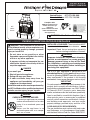
INSTALLATION &
OWNER’S MANUAL
WARNING: If the information in this manual
is not followed exactly, a fire or explosion may
result causing property damage, personal
injury or loss of life.
- Do not store or use gasoline or other
flammable vapors and liquids in the vicinity
of this or any other appliance.
- A propane cylinder not connected for use
shall not be stored in the vicinity of this or
any other appliance.
DANGER
If you smell gas:
1. Shut off gas to the appliance.
2. Extinguish any open flame.
3. If odor continues, keep away from the
appliance and immediately call your gas
supplier or fire department.
Installation and service must be performed by
an NFI Certified or other qualified professional
installer, service agency, or gas supplier.
WARNING
Improper installation, adjustment, alteration,
service, or maintenance can cause property
damage, personal injury, or loss of life. Read
the installation, operating and maintenance
instructions thoroughly before installing or
servicing this equipment.
CODE AND SUPPLY REQUIREMENTS:
The gas installation must conform with local codes
and ordinances, or, in the absence of local codes,
with the latest National Fuel Gas Code, ANSI Z223.1.
The R.H.P. gas appliance is designed as an
attended appliance. Adults must be present when
the unit is operating. DO NOT leave the unit burning
when unattended. If the product is left burning
unattended, it may cause damage or serious injury.
INSTALLER & CONSUMER: These instructions MUST
be retained with this unit for future reference.
Important: Read these instructions carefully
before starting installation of the unit.
IMPORTANT
For safe operation and proper performance of this
product and to comply with certification, listings,
and building code acceptances, use ONLY Robert
H. Peterson (R.H.P.) controls, parts, decorative
media, and accessories that have been specifically
listed or certified for use with this fireplace. Use of
other controls, parts, or accessories is prohibited
and will void all warranties, certifications, listings,
and building code approvals, and may cause
property damage, personal injury, and loss of life.
Complies with:
ANSI Z21.97/CSA 2.41 for
outdoor decorative gas
appliances
(when installed with select
R.H.P. Vented/Unvented
Gas Appliances)
WARNING: For Outdoor Use Only
DANGER
CARBON MONOXIDE HAZARD
A vented gas appliance can produce
carbon monoxide which has no odor.
Using it in an enclosed space can
kill you.
Never use the appliance in an
enclosed space such as a camper,
tent, car, or home.
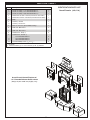
PHOENIX & MARIPOSA OUTDOOR FIREPLACES
Vented Series: 017, 073, 818, 868
Unvented Series: 117, 173, 118, 168
017
series
shown

2
REV 3 - 1910241100
L-H2-011
AVERTISSEMENT
L'installation, l'ajustement, le changement, le
service, ou l'entretien inexact peuvent causer des
dégats matériels, le dommage corporel, ou des
pertes humaines. Lisez l'installation, l'opération
et les instructions d'entretien complètement avant
d'installer ou entretenir cet équipement.
CONDITIONS DE CODE ET D'APPROVISIONNEMENT:
L'installation de gaz doit se conformer aux codes
locaux et aux ordonnances, ou, en l'absence des
codes locaux, au plus défunt code national de gaz de
carburant, la norme ANSI Z223.1.
Le R.H.P. Appareil à gaz est conçu comme un appareil
assisté. Les adultes doivent être présents lorsque
l'appareil est en marche. Ne laissez pas l'appareil est
en marche sans surveillance. Si le produit est laissé
brûler sans surveillance, il peut causer des dommages
ou des blessures graves.
AVERTISSEMENT: Si l'information en
ce manuel n'est pas suivie exactement, une
incendie ou une explosion peut résulter
entraînant des dégats matériels, le dommage
corporel ou des pertes humaines.
- Ne pas entreposer ni utiliser d'essence ou
d'autres vapeurs et liquides inflammables
à proximité de cet appareil ou de tout autre.
- Une bouteille de propane non branchée ne
doit pas être entreposée à proximité de cet
ou tout autre appareil.
DANGER
Si vous sentez une odeur de gaz:
1. Coupez le gaz à l'appareil.
2. Éteindre toute flamme nue.
3. Si l'odeur persiste, éloignez-vous de
l'appareil et appelez immédiatement votre
fournisseur de gaz ou les pompiers.
L'installation et le service doivent être
assurés par un NFI certifié ou toute autre
installateur, agence de service, ou fournisseur
professionnelle qualifiée de gaz.
d'INSTALLATEUR; CONSOMMATEUR: Ces
instructions DOIVENT être maintenues avec cet appareil
pour la future référence.
Important: Lisez ces instructions soigneusement avant
de commencer l'installation de l'unité.
IMPORTANT
Pour un fonctionnement en toute sécurité et le bon
fonctionnement de ce produit et pour être conforme à
la certification, aux listes et aux normes du bâtiment,
utilisez UNIQUEMENT les commandes, pièces,
supports décoratifs et accessoires Robert H. Peterson
(R.H.P.) spécialement homologués ou certifiés pour
être utilisés avec cette cheminée. L'utilisation d'autres
commandes, pièces ou accessoires est interdite et
annulera toutes les garanties, certifications, listages et
approbations du code du bâtiment, et pourrait causer
des dommages matériels, des blessures et la mort.
AVERTISSEMENT: Pour l'usage extérieur
seulement
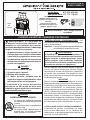
INSTALLATION ET
MODE D'EMPLOI
Conforme à:
ANSI Z21.97/CSA 2.41 pour
l'extérieur des appareils à gaz
décoratifs
(lorsqu'il est installé avec
sélection R.H.P. Ventilé / non
ventilé les appareils à gaz)
DANGER
CARBON MONOXIDE HAZARD
Un foyer à gaz ventilé peut produire
du monoxyde de carbone qui n'a pas
d'odeur.
Son utilisation dans un espace clos
peut vous tuer.
Ne jamais utiliser l'appareil dans un
espace clos, tel qu'une caravane,
tente, voiture ou à la maison.
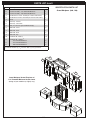
Série
017
montré
PHOENIX & MARIPOSA CHEMINÉES D'EXTÉRIEUR
Ventilé Série: 017, 073, 818, 868
Non Ventilé Série: 117, 173, 118, 168

3
REV 3 - 1910241100
L-H2-011
TABLE OF CONTENTS
GETTING STARTED
PRE-INSTALLATION AND PREPARATION SAFETY GUIDELINES �����������������������������������������������������4
INSTALLATION SAFETY GUIDELINES ���������������������������������������������������������������������������������������������������5
OPERATING THE UNIT SAFELY AND CORRECTLY �����������������������������������������������������������������������������5
SAFE USE & MAINTENANCE OF PROPANE GAS CYLINDERS ����������������������������������������������������������7
SPECIFICATIONS AND DIMENSIONS ������������������������������������������������������������������������������������������������������8
MINIMUM CLEARANCES ������������������������������������������������������������������������������������������������������������������������11
TOOLS REQUIRED ������������������������������������������������������������������������������������������������������������������������������������11
PARTS LIST ������������������������������������������������������������������������������������������������������������������������������������������������ 12
INSTALLATION
IMPORTANT SAFETY INFORMATION �������������������������������������������������������������������������������������������������� 15
FIREPLACE INSTALLATION ������������������������������������������������������������������������������������������������������������������ 15
BEFORE YOU BEGIN ��������������������������������������������������������������������������������������������������������������������������� 15
LOCATION ������������������������������������������������������������������������������������������������������������������������������������������ 15
FIREPLACE ASSEMBLY - OVERVIEW ��������������������������������������������������������������������������������������������������� 16
GAS SUPPLY SETUP (if applicable) ������������������������������������������������������������������������������������������������������ 17
FIREPLACE ASSEMBLY - STEP BY STEP ���������������������������������������������������������������������������������������������� 17
BURNER INSTALLATION ����������������������������������������������������������������������������������������������������������������������� 22
BURNER INSTALLATION GUIDELINES ������������������������������������������������������������������������������������������������ 22
LEAK TEST ������������������������������������������������������������������������������������������������������������������������������������������� 22
OPTIONAL ACCESSORIES ���������������������������������������������������������������������������������������������������������������������� 23
OPTIONAL GFRC CHIMNEY RAIN VENT CAP �������������������������������������������������������������������������������������� 23
OPTIONAL SCROLL SCREEN ��������������������������������������������������������������������������������������������������������������� 23
OPTIONAL GFRC PROTECTOR PLATE ������������������������������������������������������������������������������������������������ 23
USE, CARE, & SERVICE
LIGHTING GUIDELINES ������������������������������������������������������������������������������������������������������������������������� 25
FOR YOUR SAFETY, READ BEFORE LIGHTING ����������������������������������������������������������������������������������� 25
TO LIGHT THE APPLIANCE ����������������������������������������������������������������������������������������������������������������� 25
TO SHUT OFF GAS TO THE APPLIANCE ��������������������������������������������������������������������������������������������� 25
SERVICING AND CLEANING ����������������������������������������������������������������������������������������������������������������� 26
ANNUAL CLEAN / INSPECTION GUIDELINES ������������������������������������������������������������������������������������� 26
CONCRETE CARE �������������������������������������������������������������������������������������������������������������������������������� 27
TROUBLESHOOTING ������������������������������������������������������������������������������������������������������������������������������ 27
WARRANTY ���������������������������������������������������������������������������������������������������������������������������������������������� 28
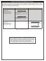
IMPORTANT SAFETY INFORMATION
Congratulations on your purchase of an American Fyre Designs outdoor gas fireplace. Made with pride in America,
your new fireplace complies with national safety standards and when installed per these instructions and used
as intended it will provide warmth and comfort to your outdoor area for many years.
Prior to installation and operation ensure that all specifications, dimensions, and minimum clearances
stated in this manual are observed. You must read all warnings and safety information, and understand
all of the information in this manual. All installation requirements must be observed and met.

4
PRE-INSTALLATION AND PREPARATION SAFETY GUIDELINES
This fireplace is designed to be installed with select R.H.P. vented/unvented gas appliances. The following
3 sections of warnings apply to this complete setup type:
A. A shut-off valve (not included) in the gas line is optional. It provides for safety when the unit is not in use
and for convenient maintenance and repair. It can be installed within 6 feet of unit. Use a pipe joint compound
resistant to all gasses on all male fittings except flare fittings.
B. Before installing this unit, check the MINIMUM CLEARANCES section to ensure that the surrounding area is
properly sized for the installation.
C. The unit is for outdoor use only. DO NOT install or use this appliance inside a building, garage, or any other
enclosed area, including recreational vehicles and/or boats. THIS UNIT MUST BE INSTALLED SO THAT
THE VENT OPENINGS AND SURROUNDING AREA OF THE UNIT REMAIN CLEAR AND FREE AT ALL
TIMES.
D. SOLID FUEL MUST NOT BE BURNED in the unit.
E. CHECK GAS TYPE (natural gas or propane): The gas supply you intend to use may not be the same as that
stated on the burner rating plate as purchased. If the gas supply is different, DO NOT INSTALL, and contact
the dealer for assistance.
F. FOR NATURAL GAS: The minimum inlet gas-supply pressure for purposes of input adjustment is 5" water
column (w.c.), and the maximum inlet gas-supply pressure is 10.5 " w.c.
FOR PROPANE GAS: The minimum inlet gas-supply pressure for purposes of input adjustment is 11" w.c., and
the maximum inlet gas-supply pressure is 13" w.c. DO NOT INSTALL THIS UNIT IF MINIMUM PRESSURE
IS NOT AVAILABLE OR IF MAXIMUM PRESSURE IS EXCEEDED.
G. The gas piping system must be sized to provide minimum inlet pressure at the maximum flow rate
(BTU/hr). Undue pressure loss will occur if the pipe is too small, or the run is too long. Gas supply pipe must
be
1
/
2
" minimum interior diameter. If the gas line is longer than 20', a larger diameter line may be necessary.
Refer to the NFPA 54 guidelines for further details.
H. For installations at elevations above 2,000 ft., contact your local dealer or gas supplier before installing. Input
ratings should be reduced approximately 4% per 1,000 ft. above sea level. Refer to National Fuel Gas Code.
I. The gas appliance and the individual shut-off valve must be disconnected from the gas-supply piping system
during any pressure testing of that system at test pressures in excess of
1
/
2
psi (3.5 kPa). This is accomplished
by closing the gas-supply line valve. The unit must be isolated from the gas-supply piping system by closing its
individual manual shut-off valve during any pressure testing of the gas-supply piping system at test pressures
equal to or less than
1
/
2
psi (3.5 kPa).
J. When a gas appliance is for connection to a fixed piping system, the installation must conform with local codes,
or in the absence of local codes with the National Fuel Gas Code, ANSI Z223.1/NFPA 54; International Fuel
Gas Code, Natural Gas and Propane Installation Code, CSA B149.1; or Propane Storage and Handling Code,
B149.2, as applicable.
K. INSTALLER NOTE: This unit should be installed so that it can be removed if service is required.
L. GAS-SUPPLY PLUMBING REQUIREMENTS
Apply only joint compounds that are resistant to all gasses on all male pipe fittings. Make sure to tighten every
joint securely. Do not use pipe joint compound to connect flare fittings. Bring the gas-supply pipe up from
beneath the hearth or directly behind the hearth as appropriate for your installation.
CAUTION: Installation and maintenance must be done by an NFI Certified or other qualified professional service
technician. Installer, read these instructions (and all other instructions provided with separately purchased
product) before installing. Be sure you understand all safety precautions and warnings contained in the
manual(s).
GETTING STARTED

5
OPERATING THE UNIT SAFELY AND CORRECTLY
INSTALLATION SAFETY GUIDELINES
A. Carefully inspect for shipping damage. If any parts are damaged, call the dealer.
B. Installation and repair should be done by a qualified professional service technician. The gas appliance should
be inspected before use and at least annually by a qualified service person. More frequent cleaning may be
required as necessary. It is imperative that control compartment, burners and circulating air passageways of
the fireplace and/or appliance are kept clean.
C. Correct installation and proper placement of the gas appliance and its decorative media is crucial to the safe
performance of the appliance. See the owner's manual provided with the gas appliance for further information.
D. DO NOT install vented fireplaces under any overhead construction.
DO NOT install unvented fireplaces under any overhead construction that is less than 3 feet above the top of
the unit.
E. Ensure that the unit is installed on a hard and level surface.
F. This fireplace must be installed so that the vent openings and surrounding area of the fireplace remain
clear and free at all times.
G. Due to high temperatures, the unit must be located out of traffic areas and away from combustibles.
A. The R.H.P. burner is a decorative gas appliance. It is not a cooking appliance.
B. SOLID FUEL MUST NOT BE BURNED in the unit.
C. When shutting the appliance down—be sure to TURN THE CONTROL VALVE FULLY OFF.
D. Children MUST be supervised when they are in the area of this unit.
E. DO NOT sit or place any part of the body, clothing, or other flammable materials on or near the unit surround.
Children and adults should be alerted to the hazard of high surface temperatures and should stay away to
avoid burns or clothing ignition. DO NOT lean into the unit when lighting or when in use.
F. Every time you use the fireplace and appliance, make sure that:
1. The area around the unit is clear and free from combustible materials, gasoline and other flammable vapors
and liquids.
2. The vent openings and surrounding area of the fireplace are clear and free at all times.
3. The hose is inspected (if applicable). See the SAFE USE & MAINTENANCE OF PROPANE-GAS CYLINDERS
section.
G. WARNING: HOT WHILE IN OPERATION AND FOLLOWING OPERATION. Serious injury can occur! DO
NOT throw trash, paper, or other flammable materials into the unit. DO NOT leave in operation when unattended.
WARNING: DO NOT operate this fireplace and appliance in the rain.
WARNING: DO NOT operate this fireplace and appliance in high-wind conditions.
H. DO NOT continue using if you smell unusual odors, or have headaches, nausea, or dizziness.
I. DO NOT store any combustible materials, gasoline, and any other flammable vapors/liquids in the vicinity of
the unit. Provide adequate clearance for servicing and operation.
J. Matches, paper, garbage, or any other material must not be thrown into the unit.
K. DO NOT use the appliance if any part of it has been underwater. Immediately call a qualified professional
service technician to inspect the appliance and to replace any part of the control system and any gas control
that has been underwater.
L. WARNING: Food cannot be consumed after coming in direct contact with the surface of the unit due to possible
contamination.

6
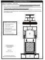
U
L
Fig. 6-1 type coupleur de fil de point culminant d’I
Valve
de
décompression
QCC
Type 1
Valve
Ajustage de précision
en laiton de fil de
point culminant
Indicateur
de niveau
de liquide
(facultatif)
Écrou de main avec le
fil de point culminant.
Régulateur
Passage
Tuyau
Volant de commande
main dans le sens des aiguilles d’une montre pour engager les
fils et pour serrer jusqu’à ce que douillettement. L’utilisation des
pinces ou de la clé ne devrait pas être nécessaire. Seulement
le propane marqué par cylindres doit être employé.
Pour débrancher: Tournez l’écrou de main dans le sens
contraire des aiguilles d’une montre jusqu’à isolé (fig. 6-1).
Important: Avant d’employer le unité, et ensuite chaque
fois que le cylindre est enlevé et rattaché,
examinez tous les raccordements pour
déceler les fuites. Arrêtez les valves de unité
et ouvrez la valve principale de cylindre, puis
vérifiez les raccordements avec de l’eau
savonneux. Réparez toutes les fuites avant
d’allumer le unité.
ATTENTION: Tournez toujours la valve principale de cylindre
de propane au loin après chaque utilisation,
et avant de déplacer le unité et le cylindre, ou
débrancher l’accouplement. Cette valve doit
rester fermée et le cylindre a débranché alors
que l’appareil n’est pas en service, quoique
l’écoulement de gaz soit arrêté par un dispositif
de sûreté quand le coupleur est débranché.
Inspectez soigneusement l’ensemble de tuyau chaque fois
avant que le gaz soit allumé. Un tuyau fissuré ou effiloché doit
être immédiatement remplacé.
Si l'appareil est stocké à l'intérieur, le cylindre doit être disconnected
et a enlevé. Des cylindres Disconnected doivent être stockés
dehors, hors de la portée des enfants, avec les prises de valve
filetées étroitement installées, et ne doivent pas être stockés dans
un bâtiment, le garage, ou n'importe quel autre secteur inclus.
POUR VOTRE SÛRETÉ
a. Ne stockez pas un cylindre de gaz disponible de propane
dessous ou ne vous approchez pas de cet appareil.
b. Ne remplissez jamais cylindre au delà de 80 pour cent de
plein.
c. SI L’INFORMATION DANS “A” ET “B” N’EST PAS SUIVIE
EXACTEMENT, UN FEU CAUSANT LA MORT OU DES
DOMMAGES SÉRIEUX PEUT SE PRODUIRE.
IMPORTANT POUR VOTRE SÛRETÉ
LISEZ ET SUIVEZ TOUS LES AVERTISSEMENTS ÉQUIPÉS DE VOTRE CYLINDRE DE GAZ DE PROPANE.
En actionnant cet appareil avec un cylindre de gaz de propane ON DOIT observer ces instructions et avertissements.
LE MANQUE DE FAIRE AINSI PEUT AVOIR COMME CONSÉQUENCE UNE INCENDIE OU UNE EXPLOSION SÉRIEUSE.
CYLINDRE ET CONDITIONS ET
CARACTÉRISTIQUES DE CONNECTEUR
a. Les bouteilles, les vannes et les tuyaux de propane doivent
être entretenus et inspectés avant chaque utilisation. Ils
doivent être remplacés en cas de dommages visibles. Si
le tuyau est coupé ou présente des signes d’abrasion ou
d’usure, il doit être remplacé avant utilisation (voir e.).
b. Cette unité, lorsqu'elle est utilisée avec une bouteille, doit
être connectée à une bouteille standard de gaz propane de
5 gallons (20 lb) équipée d'un dispositif anti-débordement
répertorié. L’appareil est obligatoire sur toutes les bouteilles
vendues depuis le 1er octobre 1998 afin d’empêcher tout
remplissage excessif.
c. Les dimensions du cylindre doivent être d'environ 12 "(30,5 cm)
de diamètre et 18" (45,7 cm) de hauteur. Les bouteilles doivent
être construites et marquées conformément aux spécifications
du ministère des Transports (DOT) pour les bouteilles à gaz LP
ou à la norme relative aux bouteilles, sphères et tubes pour le
transport des marchandises dangereuses et à la Commission,
CAN / CSA-B339, selon le cas.
d. Le cylindre doit inclure un collier pour protéger la valve
de cylindre et le circuit d’alimentation de cylindre doit être
assuré le retrait de vapeur.
e. Le montage du régulateur de pression et le flexible (Fig. 6-1)
fourni avec cet appareil au gaz en plein air (modèles au
propane seulement) doit être utilisé. Assemblées d'origine et
régulateur de pression et le tuyau de remplacement doivent
être ceux spécifiés par le fabricant pour le raccordement d'un
dispositif de cylindre de liaison identifiée comme de type I
par le ANSI Z 21.58/CGA 1.6 (voir liste des pièces pour les
informations de commande).
f. La valve de cylindre de gaz de propane doit être équipée
d’un dispositif d’accouplement de raccordement de
cylindre, décrit comme type I dans la norme définie dans le
e. de paragraphe ci-dessus. Ce dispositif est généralement
décrit comme coupleur de fil de point culminant.
g. Si votre cylindre de gaz de propane vient avec une prise
de la poussière, placez le bouchon anti-poussière sur la
sortie de valve de cylindre toutes les fois que le cylindre
n’est pas en service.
OPÉRATION DE COUPLEUR
Pour relier le regulator/hose à l’ajustage de précision de
valve de cylindre de gaz de propane: Serrez l’écrou de main
sur le régulateur au-dessus de l’ajustage de précision de fil
de point culminant sur la valve de cylindre. Tournez l’écrou de
1
2
3
4
e. Le régulateur de pression et l’ensemble de tuyau utilisé
doivent assortir les spécifications pour le type I par ANSI
Z 21.58/CGA 1.6 (voir la figue. 6-1).
UTILISATION SÛRE ET ENTRETIEN DES CYLINDRES DE GAZ DE PROPANE

7
U
L
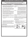
Fig. 7-1 Type I Acme thread coupler
Pressure
relief
valve
QCC
Type 1
valve
Brass Acme
thread fitting
Liquid level
indicator
(optional)
Hand nut with Acme
thread
Regulator
Vent
Hose
Hand wheel
The use of pliers or a wrench should not be necessary. Only
cylinders marked “propane” may be used.
To disconnect: Turn the hand nut counterclockwise until
detached (Fig. 7-1).
Important: Before using the unit, and after each time
the cylinder is removed and reattached,
check the hose for wear (see a.) and check
all connections for leaks. Turn off the unit
valves and open the main cylinder valve,
then check connections with soapy water.
Repair any leaks before lighting the unit.
CAUTION: Always turn the propane cylinder main valve
off after each use, and before moving the unit
and cylinder or disconnecting the coupling.
This valve must remain closed and the
cylinder disconnected while the appliance
is not in use, even though the gas flow is
stopped by a safety feature when the coupler
is disconnected.
Carefully inspect the hose assembly each time before the
gas is turned on. A cracked or frayed hose must be replaced
immediately.
If the appliance is stored indoors, the cylinder must be
disconnected and removed. Disconnected cylinders must be
stored outdoors, out of the reach of children, with threaded
valve plugs tightly installed, and must not be stored in a
building, garage, or any other enclosed area.
FOR YOUR SAFETY
a. DO NOT store a spare propane-gas cylinder under or
near this appliance.
b. NEVER fill the cylinder beyond 80-percent full.
c. IF THE INFORMATION IN a. AND b. IS NOT FOLLOWED
EXACTLY, A FIRE CAUSING DEATH OR SERIOUS
INJURY MAY OCCUR.
IMPORTANT FOR YOUR SAFETY
READ AND FOLLOW ALL WARNINGS PROVIDED WITH THE PROPANE-GAS CYLINDER.
When operating this appliance with a propane-gas cylinder, these instructions and warnings MUST be observed.
FAILURE TO DO SO MAY RESULT IN A SERIOUS FIRE OR EXPLOSION.
CYLINDER/CONNECTOR REQUIREMENTS
a. Propane-gas cylinders, valves, and hoses must be
maintained in good condition and inspected before each use
of appliance. They must be replaced if there is any visible
damage. If hose is cut or shows excessive abrasion or wear,
it must be replaced before using appliance (see e.).
b. This unit, when used with a cylinder, should be connected
to a standard 5-gallon (20 lb.) propane-gas cylinder
equipped with a listed overfilling prevention device. The
device has been required on all cylinders sold since
October 1,1998, to prevent overfilling.
c. Cylinder dimensions should be approximately 12" (30.5
cm) in diameter and 18" (45.7 cm) high. Cylinders must
be constructed and marked in accordance with the U.S.
Department of Transportation (D.O.T.) Specifications for
LP-Gas Cylinders, or the Standard for Cylinders, Spheres,
and Tubes for Transportation of Dangerous Goods and
Commission, CAN/CSA-B339, as applicable.
d. The cylinder used must include a collar to protect the
cylinder valve, and the cylinder supply system must be
arranged for vapor withdrawal.
e. The pressure regulator and hose assembly (Fig. 7-1)
supplied with this outdoor gas appliance (L.P. models
only) must be used. Original and replacement pressure
regulator and hose assemblies must be those specified by
the manufacturer for connection with a cylinder connecting
device identified as Type I by the ANSI Z 21.58/CGA 1.6
(see PARTS LIST for ordering information).
f. The propane-gas cylinder valve must be equipped with
a cylinder connection device, described as Type I in the
standard defined in paragraph e. above. This device is
commonly described as an Acme thread coupler.
g. If the propane-gas cylinder comes with a dust plug, place
the dust cap on the cylinder valve outlet whenever the
cylinder is not in use.
COUPLER OPERATION
To connect the regulator/hose assembly to the propane-
gas cylinder valve fitting: Press the hand nut on the regulator
over the Acme thread fitting on the cylinder valve. Turn the hand
nut clockwise to engage the threads and tighten until snug.
e. The pressure regulator and hose assembly used must
match the specification for Type I by ANSI Z 21.58/CGA
1.6 (see Fig. 7-1).
SAFE USE & MAINTENANCE OF PROPANE GAS CYLINDERS

8
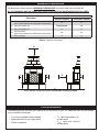
SPECIFICATIONS AND DIMENSIONS
Style Dimensions Weight / Pieces
Phoenix Fireplace (017 & 117) * 65" w x 36" d x 87" h 1100 lbs / 7 pcs
Grand Phoenix Fireplace (818 & 118) † 113" w x 36" d x 87" h 1400 lbs / 13 pcs
Mariposa Fireplace (073 & 173) * 65" w x 36" d x 67" h 970 lbs / 7 pcs
Grand Mariposa Fireplace (868 & 168) † 113" w x 36" d x 67" h 1300 lbs / 13 pcs
* Dimensions, Weight, & Pieces listed based upon a standard 16" Radiused Bullnose Hearth.
† Dimensions, Weight, & Pieces listed based upon an 113" Extended Bullnose Hearth.
Table 1 - Product Specifications
2" Recess Option
The above fireplaces (except Grand models) are offered with a 2" recess option. This results in
certain areas of the fireplace (flat surfaces of the body and/or hearth) being "recessed" inward.
These reduced dimensions allow for the fireplace to be customized with a finishing substrate
(i.e. tiles/stonework). Contact your local American Fyre Designs dealer for further details.
Depth
Height
Phoenix Fireplace
Width
Depth
Height
Grand Mariposa Fireplace
Width
Select Models
Shown
(your model may vary)

9
SPECIFICATIONS AND DIMENSIONS (cont.)
Style Dimensions *
16" Radiused Bullnose Hearth (01) 65" w x 36" d x 16" h
16" Rectangle Bullnose Hearth (02) 65" w x 36" d x 16" h
16" Roundover Hearth (03) 52" w x 32" d x 16" h
4" Roundover Hearth (04) 52" w x 32" d x 4" h
113" Extended Bullnose Hearth (05) 113" w x 36" d x 16" h
137" Extended Bullnose Hearth (06) 137" w x 36" d x 16" h
160" Extended Bullnose Hearth (07) 160" w x 36" d x 16" h
Corner Square Edge Hearth (08) Refer to drawing below
* See previous page for 2" Recess Option information.
Table 2 - Hearth Dimensions
16" Rectangle Bullnose Hearth 16" Radiused Bullnose Hearth
Corner Square Edge Hearth
Depth
Height
Width
Select Models
Shown
(your model may vary)
Depth
Height
Width
55"
54"
100"
33"
16"
130"
23"

10
SPECIFICATIONS AND DIMENSIONS (cont.)
This fi replace is designed to be installed with an R.H.P. vented/unvented gas appliance. Below is a list of
the options available for each fi replace type. The gas appliance is purchased separately. Contact your local
American Fyre Designs dealer when ordering.
Fireplace Styles Vented Burner Options Unvented Burner Options
Phoenix (017),
Grand Phoenix (818),
Mariposa Fireplace (073),
Grand Mariposa (868)
G45 STAINLESS STEEL
(Log Set or Glass Models)
Match-Lit Models: up to 24" burners
Valve Models: up to 18/20" burners
G22 STAINLESS STEEL
Match-Lit Models: up to 24" burners
Valve Models: up to 18" burners
-
Phoenix (117),
Grand Phoenix (118),
Mariposa Fireplace (173),
Grand Mariposa (168)
-
G10 STAINLESS STEEL
up to 24/30" burners with 24" log set
G21 STAINLESS STEEL
up to 24" burners
Table 3 - Fireplace Burner Options
The unit's marking label plate is located in the interior of the
fi rebox. It hangs from a chain on the front inner wall (valve side).
Ensure the plate is placed behind the side liner during installation.
To view, simply reach in, access, then return once done.
For unvented models, the top liner must be moved to one side.

11
The dimensions shown below are MINIMUM CLEARANCES to maintain when you install the unit.
ALL CLEARANCES AND INFORMATION STATED HERE MUST BE MAINTAINED AND FOLLOWED.
MINIMUM CLEARANCES
Table 4 - Minimum Clearances
Floor must be a hard, level surface. Combustible materials permitted.
Description
Dimension
Vented Fireplace Unvented Fireplace
A. Side clearance
(from hearth extension to combustible construction)
6" 6"
B. Clearance above unit
Not permitted
36"
C. Clearance below unit 0" 0"
D.
Front clearance
(from hearth extension to combustible construction)
36" 36"
E. Rear clearance 6" 6"
B
A
C
E
A
D
TOOLS REQUIRED
The following are the minimum tools required for the installation of your unit. Additional tools may be required
for your individual installation.
• 2 (or more) assemblers recommended
• appropriate tools for gas supply install
• Phillips screwdriver
•
3
/
4
" open-end wrenches (2)
(or equivalent)
• 9
/
16
" open-end wrench
(or equivalent)

12
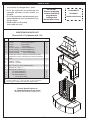
PARTS LIST
IMPORTANT
Remove all packing
material (including
any protective
coatings) and
discard prior to use.
• Your fireplace is packaged onto 1 pallet.
• R.H.P. gas appliances are purchased and
packaged separately. Various models are
available.
• R.H.P. gas appliances and replacement parts
can be ordered from your local American Fyre
Designs dealer.
• Select models are illustrated
(your model may vary)
COMPONENTS
ARE HEAVY
HANDLE WITH CARE
IDENTIFICATION PARTS LIST
Phoenix (017, 117), Mariposa (073, 173)
1
2
4
3
Phoenix Vented Fireplace w/
16" Radiused Bullnose Hearth shown
(design of your model may slightly vary)
Item Description Qty.
1.
or
or
or
or
or
or
or
Hearth - 16" Radiused Bullnose
Hearth - 16" Rectangle Bullnose *
Hearth - 16" Roundover *
Hearth - 4" Roundover *
Hearth assembly - 113" Extended Bullnose *
Hearth assembly - 137" Extended Bullnose *
Hearth assembly - 160" Extended Bullnose *
Hearth assembly - Corner Square Edge *
1
1
1
1
1
1
1
1
2.
or
Firebox liners w/ shims - Vented (set of 4 liners and 2 shims)
Firebox liners w/ shims - Unvented (set of 5 liners and 2 shims) *
1
1
3. Body 1
4.
or
Chimney - Vented
Chimney - Unvented *
1
1
5. Bolt,
3
/
8
"-16 x 2.5" (pre-installed in body)* 2
6. Hardware kit - Body *
†
4
7.
or
or
or
Hardware kit - Hearth *
†
‡
113" Extended Bullnose
137" Extended Bullnose
160" Extended Bullnose
Corner Square Edge
8
8
8
8
* not shown
†
each kit contains: (1)
1
/
2
"-13 x 3.5" bolt, (1) nut, (2) washers
‡ only required / included with multi-piece large hearths

13
PARTS LIST (cont.)
IDENTIFICATION PARTS LIST
Grand Phoenix (818, 118)
1
2
3
1
4
Item Description Qty.
1.
or
or
Hearth assembly - 113" Extended Bullnose
Hearth assembly - 137" Extended Bullnose *
Hearth assembly - 160" Extended Bullnose *
1
1
1
2.
or
Firebox liners w/ shims - Vented (set of 4 liners and 2 shims)
Firebox liners w/ shims - Unvented (set of 5 liners and 2 shims) *
1
1
3. Body 1
4.
or
Chimney - Vented
Chimney - Unvented *
1
1
5. Bolt,
3
/
8
"-16 x 2.5" (pre-installed in body)* 2
6. Side wall - Main Piece 2
7. Side wall - Rear Piece 2
8. Hardware kit - Body*
†
8
9.
or
or
Hardware kit - Hearth*
†
113" Extended Bullnose
137" Extended Bullnose
160" Extended Bullnose
8
8
8
10. Concrete Phillips screw,
1
/
4
" x 1
3
/
4
" * 8
* not shown
†
each kit contains: (1)
1
/
2
"-13 x 3.5" bolt, (1) nut, (2) washers
Grand Phoenix Vented Fireplace w/
113" Extended Bullnose Hearth shown
(design of your model may slightly vary)
1
6
6
7
7

14
PARTS LIST (cont.)
IDENTIFICATION PARTS LIST
Grand Mariposa (868, 168)
1
2
3
1
4
Grand Mariposa Vented Fireplace w/
113" Extended Bullnose Hearth shown
(design of your model may slightly vary)
1
6
6
9
9
Item Description Qty.
1.
or
or
Hearth assembly - 113" Extended Bullnose
Hearth assembly - 137" Extended Bullnose *
Hearth assembly - 160" Extended Bullnose *
1
1
1
2.
or
Firebox liners w/ shims - Vented (set of 4 liners and 2 shims)
Firebox liners w/ shims - Unvented (set of 5 liners and 2 shims) *
1
1
3. Body 1
4.
or
Chimney - Vented
Chimney - Unvented *
1
1
5. Bolt,
3
/
8
"-16 x 2.5" (pre-installed in body)* 2
6. Side wall - Front 2
7. Side wall - Rear 2
8. Side wall - End 2
9. Side wall - Top 2
10. Hardware kit - Body*
†
14
11.
or
or
Hardware kit - Hearth*
†
113" Extended Bullnose
137" Extended Bullnose
160" Extended Bullnose
8
8
8
* not shown
†
each kit contains: (1)
1
/
2
"-13 x 3.5" bolt, (1) nut, (2) washers
8
7
7
8
INSTALLATION

15
IMPORTANT SAFETY INFORMATION
BE CAREFUL
If not installed and used correctly per these instructions,
this product can cause serious injury.
CAUTION: Installation and maintenance must be done by an NFI Certified or other qualified professional service
technician. Read these instructions before installing this fireplace and the R.H.P. gas appliance. Be
sure you understand all safety precautions and warnings contained in this manual and the appliance
owner's manual.
A. FOR OUTDOOR USE ONLY.
B. When shutting the gas appliance down—be sure to TURN THE CONTROL VALVE OR KEY FULLY OFF.
C. WARNING: CARBON MONOXIDE POISONING MAY LEAD TO DEATH. DO NOT MODIFY THIS FIREPLACE
OR THE GAS APPLIANCE, EXCEPT AS PROVIDED FOR IN THE MANUALS. Any other change may be
dangerous. Improper installation or use of the fireplace and R.H.P. gas appliance can cause serious injury or
death from fire, burns, explosions, or carbon monoxide poisoning.
D. Check state and local codes to determine if the fireplace and R.H.P. gas appliance are permitted in your
locality before installation.
E. Select models allow for an adjustable flame height. THESE SETTINGS MUST ALWAYS BE HIGH ENOUGH
FOR THE FLAME TO BE CLEARLY VISIBLE. WHEN LIGHTING THE APPLIANCE, ALWAYS LIGHT ON HIGH.
FIREPLACE INSTALLATION
BEFORE YOU BEGIN
Important: Prior to installation ensure that all specifications, dimensions, and minimum clearances stated
in this manual are observed. You must read all warnings and safety information, and understand
all of the information in this manual. All installation requirements must be observed and met.
WARNING: Failure to position the parts in accordance with these diagrams or failure to use only parts specifically
approved with this unit may result in property damage or personal injury.
• Confirm the installation site accommodates the fireplace per the requirements in this manual.
• Be sure the gas supply (propane or natural) is turned off at its source.
• Remove all packing material (including any protective coatings) and discard prior to installation.
LOCATION
While following all requirements and safety information in this manual (see MINIMUM CLEARANCES section);
determine and prepare the location of the fireplace (a hard and level surface).
Note: For fireplaces, a combustible surface is permitted.
Important: The gas supply must be considered when determining the location of the unit. See GAS
SUPPLY SETUP section for details.
ASSEMBLY REQUIRES TWO OR MORE PEOPLE.
EXERCISE EXTREME CARE DURING ASSEMBLY AND INSTALLATION.
INSTALLATION

16
FIREPLACE INSTALLATION (cont.)
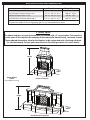
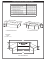
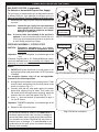
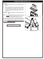
FIREPLACE ASSEMBLY - OVERVIEW
CAUTION: Fireplace components are heavy. CAREFULLY handle all components during assembly.
• Fig. 16-1 provides an overall orientation and bolt assembly detail for the fireplace.
(Phoenix w/ 16" Radiused Bullnose Hearth shown. Mariposa and Grand models assemble in a similar manner.
Assembly may slightly vary depending on model and hearth selected.)
• Grand models have the addition of side walls, which are addressed in the following step-by-step section.
• This section is just an overview, refer to the following step-by-step section for complete assembly
and installation details.
Fig. 16-1
Overall Orientation
Phoenix Fireplace w/
16" Radiused Bullnose
Hearth shown
ASSEMBLY / INSTALL OVERVIEW
1. Place / Assemble hearth *
2. Assemble body
3. Connect gas (not shown)
4. Assemble side walls
(Grand models only, not shown)
5. Install firebox liners and shims
6. Assemble chimney
7. Install burner (not shown)
2
5
6
1*
* One-piece hearth shown here.
Multi-piece hearths require assembly.

17
FIREPLACE INSTALLATION (cont.)
GAS SUPPLY SETUP (if applicable)
For Natural or Household Propane Gas Supply:
The gas supply is to be brought up from beneath the hearth
or directly behind it. Your individual installation may vary.
Observe the National Fuel Gas Code and all local codes.
1. Route the gas supply into the area that the hearth will
rest over.
Important: Locate the gas supply line out of pathways
where people may trip over it or in areas
where the line may be subject to accidental
damage (if applicable).
Note: A shut-off valve (not included) in the gas line is
optional. It can be installed within 6 feet of the unit.
Use a pipe joint compound resistant to all gasses on
all male fittings except flare fittings.
FIREPLACE ASSEMBLY - STEP BY STEP
CAUTION: Fireplace components are heavy.
CAREFULLY handle all components during
assembly.
Important: DO NOT overtighten (to avoid damage to the
unit).
A Phoenix Fireplace with a 16" Radiused Bullnose Hearth
is primarily depicted here. Your assembly may slightly vary
depending on model and hearth selected.
Hearth
1. CAREFULLY place the hearth or hearth pieces in an
appropriate location (refer back to the LOCATION section
if needed).
For one-piece hearths, step 2-5 are not applicable:
proceed to the following section.
2. Arrange the hearth pieces in their proper position. Then
insert the bolts and washers into the outer pieces of the
hearth as shown in Fig. 17-1.
3. Carefully slide the left outer-piece against the center
piece while aligning the pilot holes. Then reach into
the center hearth (through access opening), place the
washers and nuts, and hand tighten. See Fig. 17-2.
4. Use a
3
/
4
" open end wrench (or equivalent) to apply a
1/4 turn to secure.
Important: DO NOT overtighten (to avoid damage to the
unit).
5. Repeat for the right outer-piece.
Fig. 17-1 Assemble hearth - arrange (if required)
Hardware:
Bolts x 8
Washers x 8
3 piece
hearth shown
Fig. 17-2 Assemble hearth - slide together & fasten
Fig. 17-3 Hearth assembled
Hardware:
Nuts x 8
Washers x 8
An alternative method for access is to CAREFULLY tilt
the hearth pieces on their back. Use 2x4s as wedges to
ensure the pieces remain upright during the procedure.
Use extreme care when lifting/lowering the pieces to
prevent injury or damage. It is recommended to rest
cardboard over the work space (to prevent damage).
Remove after assembly.
B
C
Slide
together
Fasten with
nuts & washers
A
Insert bolts
& washers
(Assemble all pieces)

18
FIREPLACE INSTALLATION (cont.)
Body
1. Place the body piece on top of the hearth. Carefully
align the pilot holes, and insert the hardware in the order
shown in Fig. 18-1. Hand tighten, then use two
3
/
4
" open
end wrenches (or equivalent) to fasten.
Note: It is recommended to rest cardboard on the hearth
when positioning the body (to prevent damage to the
hearth surface). Remove once positioned.
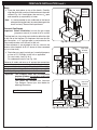
Connect Gas Supply
Important: Before installation, be sure the gas supply
(propane or natural) is turned off at its source.
The fireplace has a key valve pre-installed on either the right
or left side of the fireplace. For fireplaces that have the rear
gas line option, a
1
/
2
" rigid gas pipe is pre-installed to the
valve and protrudes out of the rear of the unit.
(A flex connector is pre-attached to the key valve on the
interior of the fireplace. An R.H.P. burner is to be connected
to it at a later time.)
1. Route the gas supply (natural gas, household propane,
or from an L.P. Cylinder) to the unit as applicable.
For rear installs, see Fig. 18-2.
For underneath installs, see Fig. 18-3.
Observe all codes and ensur e all appropriate connections
are used to properly connect the gas supply. Apply only joint
compounds that are resistant to all gasses to all male pipe
fittings except flare fittings. Make sure to tighten every joint
securely and properly leak test at all connections.
Important: This fireplace does not accommodate
propane cylinders. If a cylinder is used it must
be located in a safe location.
Tank tables are available from American
Fyre Designs. Contact your local dealer for
ordering information.
Fig. 18-2 Route gas supply (rear install)
(key valve
location
may vary)
Fig. 18-3 Route gas supply (underneath install)
(key valve
location
may vary)
Key valve
Flex
connector
Connect
here
Connect here
(from below)
Key valve
Flex
connector
Installation continued on next page
Fig. 18-1 Assemble body
Hardware:
Bolts x 4
Nuts x 4
Washers x 8

19
FIREPLACE INSTALLATION (cont.)
For standard models proceed to the LINERS section.
For Grand models, continue on to the following
section.
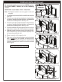
MARIPOSA Grand Models ONLY - Side Walls
Note: For Phoenix models, see next page for side wall
assembly.
1. Locate the four pieces required to assemble one complete
side wall.
2. Place the rear side-wall piece beside the fi replace body
as shown. Carefully align the pilot holes, and repeat the
hardware installation process. See Fig. 19-1.
3. Place the front side-wall piece beside the fi replace body
as shown. Carefully align the pilot holes, and repeat the
hardware installation process. See Fig. 19-2.
4. Place the end side-wall piece against the front and rear
side-walls as shown in Fig. 19-3 (no hardware required).
5. Slide the top side-wall piece onto the front and rear side-
walls as shown in Fig. 19-4 (no hardware required). This
will secure the entire side wall.
6. Repeat assembly for the opposite side.
7. The seams of the side wall pieces must be fi nished
with a sanded grout (not included) according to color
preference (see Fig. 19-5). The grout can be purchased
at a local hardware store. Follow all instructions provided
with the grout.
Installation continued on next page
Fig. 19-1 Assemble rear side-wall (skip if n/a)
Fig. 19-2 Assemble front side-wall (skip if n/a)
Fig. 19-3 Assemble end side-wall (skip if n/a)
Fig. 19-4 Assemble top side-wall (skip if n/a)
MARIPOSA Grand
Models Only:
Side Walls
Hardware:
Bolts x 3
Nuts x 3
Washers x 6
Hardware:
Bolts x 2
Nuts x 2
Washers x 4
Fig. 19-5 Grout seams (skip if n/a)
Grout seams

20
FIREPLACE INSTALLATION (cont.)
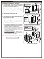
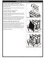
PHOENIX Grand Models ONLY - Side Walls
1. Place one main side-wall piece beside the fi replace body
as shown. Carefully align the pilot holes, and repeat the
hardware installation process. See Fig. 20-1.
2. Each rear side-wall piece is marked to align the detail.
Place the correct rear side-wall piece in position against
the rear of the main piece, then fasten using a Phillips
screwdriver and the supplied concrete screws (see Fig.
20-2).
3. Repeat assembly for the opposite side.
Liners
1. Install the fi rebox liners into the interior of the fi rebox in
the order shown in Fig. 20-3:
• The bottom and rear liners have grooves to assist in
placement.
• The two shims "D" are to be wedged between liner
"B" and the rear wall by hand as shown. The shims
secure the liner set in place.
• Be sure to pull the fl ex connector inside of the fi replace
body through the liner and into the open interior of the
fi rebox (for later R.H.P. burner installation).
• Ensure the unit's marking label plate is placed behind
the side liner during installation. It is located in the
interior of the fi rebox, and hangs from a chain on the
front inner wall (valve side).
• For Unvented Fireplaces: An additional liner "E"
exists and is to be installed onto the top of the fi rebox
(through the top of the body piece).
Note: The liners rest in place. No hardware is required.
Fig. 20-3 Install fi rebox liners
A
B
C
C
E
Be sure to pull fl ex
connector through liner
Unvented fi replaces
contain a liner for the
top of the fi rebox.
D
D
Installation continued on next page
Fig. 20-1 Assemble side-wall (skip if n/a)
Fig. 20-2 Assemble rear side-wall (skip if n/a)
PHOENIX Grand
Models Only:
Side Walls
Hardware:
Bolts x 2
Nuts x 2
Washers x 4
Hardware:
1/4" x 1 3/4"
Concrete
Screws
(x 4)
Rear view
Align detail
La page est en cours de chargement...
La page est en cours de chargement...
La page est en cours de chargement...
La page est en cours de chargement...
La page est en cours de chargement...
La page est en cours de chargement...
La page est en cours de chargement...
La page est en cours de chargement...
-
 1
1
-
 2
2
-
 3
3
-
 4
4
-
 5
5
-
 6
6
-
 7
7
-
 8
8
-
 9
9
-
 10
10
-
 11
11
-
 12
12
-
 13
13
-
 14
14
-
 15
15
-
 16
16
-
 17
17
-
 18
18
-
 19
19
-
 20
20
-
 21
21
-
 22
22
-
 23
23
-
 24
24
-
 25
25
-
 26
26
-
 27
27
-
 28
28


R.H. Peterson American Fyre Designs 117 Installation & Owner's Manual
- Catégorie
- Cheminées
- Taper
- Installation & Owner's Manual
dans d''autres langues
Documents connexes
Autres documents
-
GROHE 26632EN0 Guide d'installation
-
USSC HCGV1 Mode d'emploi
-
 RST Brands OP-PSCLB5MFT-GY-K Mode d'emploi
-
Real Fyre G52 Stainless Steel Vented Burner Systems Le manuel du propriétaire
-
Alfresco AXE-PZA Pizza Oven Plus Manuel utilisateur
-
-
-
Fire Magic Sideburner Manuel utilisateur
-
AOG Drop In Sideburner Manuel utilisateur
-
Fire Magic Gourmet Single and Double Searing Station Manuel utilisateur
