Manitowoc Q Model Undercounter Guide d'installation
- Catégorie
- Fabricants de glaçons
- Taper
- Guide d'installation
Ce manuel convient également à

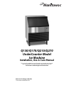
Installation, Use & Care Manual
America’s #1 Selling Ice Machine
This manual is updated as new information and models are released.
Visit our website for the latest manual. www.manitowocice.com
This manual contains English and French text
Q130/Q170/Q210/Q270
UnderCounter Model
Ice Machine
Manitowoc
Part Number 040002380 9/12

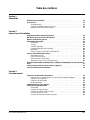
Table of Contents
2 Part Number 040002380 9/12
Section 1
General Information
Model Numbers . . . . . . . . . . . . . . . . . . . . . . . . . . . . . . . . . . . . . . . . . . . . . . . . . . . . . 4
Accessories . . . . . . . . . . . . . . . . . . . . . . . . . . . . . . . . . . . . . . . . . . . . . . . . . . . . . . . 4
Bin Caster . . . . . . . . . . . . . . . . . . . . . . . . . . . . . . . . . . . . . . . . . . . . . . . . . . . . . 4
Arctic Pure Water Filter System . . . . . . . . . . . . . . . . . . . . . . . . . . . . . . . . . . . . . 4
Manitowoc Cleaner and Sanitizer . . . . . . . . . . . . . . . . . . . . . . . . . . . . . . . . . . . 4
Section 2
Installation Instructions
Location of Ice Machine . . . . . . . . . . . . . . . . . . . . . . . . . . . . . . . . . . . . . . . . . . . . . . 5
Ice Machine Heat of Rejection . . . . . . . . . . . . . . . . . . . . . . . . . . . . . . . . . . . . . . . . . 5
Leveling the Ice Machine . . . . . . . . . . . . . . . . . . . . . . . . . . . . . . . . . . . . . . . . . . . . . 5
Electrical Service . . . . . . . . . . . . . . . . . . . . . . . . . . . . . . . . . . . . . . . . . . . . . . . . . . . 6
General . . . . . . . . . . . . . . . . . . . . . . . . . . . . . . . . . . . . . . . . . . . . . . . . . . . . . . . 6
Voltage . . . . . . . . . . . . . . . . . . . . . . . . . . . . . . . . . . . . . . . . . . . . . . . . . . . . . . . 6
Fuse/Circuit Breaker . . . . . . . . . . . . . . . . . . . . . . . . . . . . . . . . . . . . . . . . . . . . . 6
Total Circuit Ampacity . . . . . . . . . . . . . . . . . . . . . . . . . . . . . . . . . . . . . . . . . . . . 6
Ground Fault Circuit Interrupter . . . . . . . . . . . . . . . . . . . . . . . . . . . . . . . . . . . . . 6
Q130/Q170/Q210/Q270 Ice Machine . . . . . . . . . . . . . . . . . . . . . . . . . . . . . . . . 6
Water Service/Drains . . . . . . . . . . . . . . . . . . . . . . . . . . . . . . . . . . . . . . . . . . . . . . . . 7
Water Supply . . . . . . . . . . . . . . . . . . . . . . . . . . . . . . . . . . . . . . . . . . . . . . . . . . . 7
Water Inlet Lines . . . . . . . . . . . . . . . . . . . . . . . . . . . . . . . . . . . . . . . . . . . . . . . . 7
Drain Connections . . . . . . . . . . . . . . . . . . . . . . . . . . . . . . . . . . . . . . . . . . . . . . . 7
Cooling Tower Applications . . . . . . . . . . . . . . . . . . . . . . . . . . . . . . . . . . . . . . . . 7
Water Supply and Drain Line Sizing/Connections . . . . . . . . . . . . . . . . . . . . . . . . 8
Before Starting the Ice Machine . . . . . . . . . . . . . . . . . . . . . . . . . . . . . . . . . . . . . . . 9
Installation Checklist . . . . . . . . . . . . . . . . . . . . . . . . . . . . . . . . . . . . . . . . . . . . . . . . 9
Section 3
Operation
Ice Making Sequence of Operation . . . . . . . . . . . . . . . . . . . . . . . . . . . . . . . . . . . . . 10
Initial Start-up Or Start-up After Automatic Shut-off . . . . . . . . . . . . . . . . . . . . . . 10
Freeze Sequence . . . . . . . . . . . . . . . . . . . . . . . . . . . . . . . . . . . . . . . . . . . . . . . 10
Harvest Sequence . . . . . . . . . . . . . . . . . . . . . . . . . . . . . . . . . . . . . . . . . . . . . . . 10
Automatic Shut-off . . . . . . . . . . . . . . . . . . . . . . . . . . . . . . . . . . . . . . . . . . . . . . . 10
Energized Parts Chart . . . . . . . . . . . . . . . . . . . . . . . . . . . . . . . . . . . . . . . . . . . . . . . 11
Operational Checks . . . . . . . . . . . . . . . . . . . . . . . . . . . . . . . . . . . . . . . . . . . . . . . . . 12
General . . . . . . . . . . . . . . . . . . . . . . . . . . . . . . . . . . . . . . . . . . . . . . . . . . . . . . . 12
Siphon System . . . . . . . . . . . . . . . . . . . . . . . . . . . . . . . . . . . . . . . . . . . . . . . . . 12
Water Float Valve Check . . . . . . . . . . . . . . . . . . . . . . . . . . . . . . . . . . . . . . . . . . 12
Water Level Check . . . . . . . . . . . . . . . . . . . . . . . . . . . . . . . . . . . . . . . . . . . . . . 13
Ice Bridge Thickness Check . . . . . . . . . . . . . . . . . . . . . . . . . . . . . . . . . . . . . . . 13

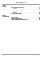
Table of Contents (continued)
Part Number 040002380 9/12 3
Section 4
Maintenance
Interior Cleaning and Sanitizing . . . . . . . . . . . . . . . . . . . . . . . . . . . . . . . . . . . . . . . 14
General . . . . . . . . . . . . . . . . . . . . . . . . . . . . . . . . . . . . . . . . . . . . . . . . . . . . . . . 14
Cleaning and Sanitizing Procedure . . . . . . . . . . . . . . . . . . . . . . . . . . . . . . . . . . 14
Ice Machine Inspection . . . . . . . . . . . . . . . . . . . . . . . . . . . . . . . . . . . . . . . . . . . . . . 20
Exterior Cleaning . . . . . . . . . . . . . . . . . . . . . . . . . . . . . . . . . . . . . . . . . . . . . . . . . . . 20
Cleaning the Condenser . . . . . . . . . . . . . . . . . . . . . . . . . . . . . . . . . . . . . . . . . . . . . 20
General . . . . . . . . . . . . . . . . . . . . . . . . . . . . . . . . . . . . . . . . . . . . . . . . . . . . . . . 20
Removal from Service/Winterization . . . . . . . . . . . . . . . . . . . . . . . . . . . . . . . . . . . 20
Section 5
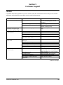
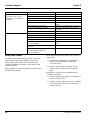
Customer Support
Checklist . . . . . . . . . . . . . . . . . . . . . . . . . . . . . . . . . . . . . . . . . . . . . . . . . . . . . . . . . . 21
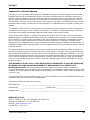
Safety Limit Feature . . . . . . . . . . . . . . . . . . . . . . . . . . . . . . . . . . . . . . . . . . . . . . . . . 22
Commercial Ice Machine Warranty . . . . . . . . . . . . . . . . . . . . . . . . . . . . . . . . . . . . 23
Residential Ice Machine Limited Warranty . . . . . . . . . . . . . . . . . . . . . . . . . . . . . . 24

4 Part Number 040002380 9/12
Section 1
General Information
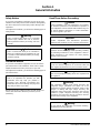
Safety Notices
As you work on Manitowoc equipment, be sure to pay close
attention to the safety notices in this handbook. Disregarding
the notices may lead to serious injury and/or damage to the
equipment.
Throughout this handbook, you will see the following types of
safety notices:
Procedural Notices
As you work on Manitowoc equipment, be sure to read the
procedural notices in this handbook. These notices supply
helpful information which may assist you as you work.
Throughout this handbook, you will see the following types of
procedural notices:
NOTE: Text set off as a Note provides you with simple, but
useful, extra information about the procedure you are
performing.
Read These Before Proceeding:
!
Warning
Text in a Warning box alerts you to a potential
personal injury situation. Be sure to read the
Warning statement before proceeding, and work
carefully.
!
Caution
Text in a Caution box alerts you to a situation in
which you could damage the equipment. Be sure
to read the Caution statement before proceeding,
and work carefully.
Important
Text in an Important box provides you with
information that may help you perform a
procedure more efficiently. Disregarding this
information will not cause damage or injury, but it
may slow you down as you work.
!
Caution
Proper installation, care and maintenance are essential
for maximum performance and trouble-free operation of
your equipment. Visit our website www.manitowocfsg.com
for manual updates, translations, or contact information
for service agents in your area.
Important
Routine adjustments and maintenance procedures
outlined in this handbook are not covered by the warranty.
!
Warning
Read this manual thoroughly before operating, installing
or performing maintenance on the equipment. Failure to
follow instructions in this manual can cause property
damage, injury or death.
!
Warning
Do not use electrical appliances or accessories other than
those supplied by Manitowoc for your ice machine model.
!
Warning
Two or more people or a lifting device are required to lift
this appliance.
!
Warning
This equipment contains high voltage electricity and
refrigerant charge. Installation and repairs are to be
performed by properly trained technicians aware of the
dangers of dealing with high voltage electricity and
refrigerant under pressure.The technician must also be
certified in proper refrigerant handling and servicing
procedures. All lockout and tag out procedures must be
followed when working on this equipment.
!
Warning
Do not damage the refrigeration circuit when installing,
maintaining or servicing the unit.

Section 1 General Information
Part Number 040002380 9/12 5
!
Warning
Do not operate equipment that has been misused, abused,
neglected, damaged, or altered/modified from that of original
manufactured specifications. This appliance is not intended
for use by persons (including children) with reduced physical,
sensory or mental capabilities, or lack of experience and
knowledge, unless they have been given supervision
concerning use of the appliance by a person responsible for
their safety. Do not allow children to play with this appliance.
!
Warning
All covers and access panels must be in place and
properly secured, before operating this equipment.
!
Warning
Do not obstruct machine vents or openings.
!
Warning
Do not store gasoline or other flammable vapors or liquids
in the vicinity of this or any other appliance.
!
Warning
Do not clean with water jet.
!
Warning
It is the responsibility of the equipment owner to perform
a Personal Protective Equipment Hazard Assessment to
ensure adequate protection during maintenance
procedures.
!
Warning
Some 50 hz models may contain up to 150 grams of R290
(propane) refrigerant. R290 (propane) is flammable in
concentrations of air between approximately 2.1% and 9.5%
by volume (LEL lower explosion limit and UEL upper
explosion limit). An ignition source at a temperature higher
than 470°C is needed for a combustion to occur. Refer to
nameplate to identify the type of refrigerant in your
equipment. Only trained and qualified personnel aware of the
dangers are allowed to work on the equipment.
!
Warning
When using electric appliances, basic precautions must
always be followed, including the following:
a. Read all the instructions before using the
appliance.
b. To reduce the risk of injury, close supervision is
necessary when an appliance is used near
children.
c. Do not contact moving parts.
d. Only use attachments recommended or sold by
the manufacturer.
e. Do not use outdoors.
f. For a cord-connected appliance, the following
must be included:
• Do not unplug by pulling on cord. To unplug,
grasp the plug, not the cord.
• Unplug from outlet when not in use and
before servicing or cleaning.
• Do not operate any appliance with a
damaged cord or plug, or after the appliance
malfunctions or is dropped or damaged in
any manner. Contact the nearest authorized
service facility for examination, repair, or
electrical or mechanical adjustment.
g. Follow applicable lock out tag out procedures
before working on equipment.
h. Connect to a properly grounded outlet only.
!
Warning
Objects placed or dropped in the bin can affect human
health and safety. Locate and remove any objects
immediately.
Important
The Commonwealth of Massachusetts requires that
all water-cooled models must be connected only to a
closed loop, cooling tower system.

General Information Section 1
6
Part Number 040002380 9/12
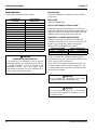
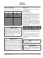
Model Numbers
This manual covers the following models:
Accessories
Contact your Manitowoc distributor for these optional
accessories:
BIN CASTER
Replaces standard legs.
ARCTIC PURE WATER FILTER SYSTEM
Engineered specifically for Manitowoc ice machines,
Arctic Pure water filters are an efficient, dependable, and
affordable method of inhibiting scale formation, filtering
sediment, and removing chlorine taste and odor.
MANITOWOC CLEANER AND SANITIZER
Manitowoc Ice Machine Cleaner and Sanitizer are
available in convenient 16 oz. (473 ml) and 1 gal (3.78 l)
bottles. These are the only cleaner and sanitizer
approved for use with Manitowoc products.
NOTE: The Manitowoc Automatic Cleaning System
(AUCS®) accessory cannot be used with models Q130,
Q170, Q210 or Q270 ice machines.
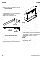
Q130, Q170, Q210 and Q270 model ice machines do
not have a water curtain covering the evaporator. The
ice damper performs the functions of the water curtain
see Section 4 for details.
Self-Contained
Air-Cooled
Self-Contained
Water-Cooled
QR0130A QR0131W
QD0132A QD0133W
QY0134A QY0135W
QD0172A --
QY0174A --
QR0210A QR0211W
QD0212A QD0213W
QY0214A QY0215W
QYP0214A --
QR0270A QR0271W
QD0272A QD0273W
QY0274A QY0275W
QYP0274A --
!
Warning
PERSONAL INJURY POTENTIAL
This appliance is not intended for use by persons
(including children) with reduced physical, sensory
or mental capabilities, or lack of experience and
knowledge, unless they have been given
supervision concerning use of the appliance by a
person responsible for their safety.
Cleaner Part Number Sanitizer Part Number
16oz 94-0456-3 16oz 94-0565-3
1 Gallon 94-0580-3 1 Gallon 94-0581-3
!
Warning
Do not damage the refrigeration circuit when
installing, maintaining or servicing the unit.
!
Warning
Do not use electrical appliances or accessories
other than those supplied by Manitowoc for your
ice machine model.

Part Number 040002380 9/12 7
Section 2
Installation Instructions
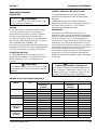
Location of Ice Machine
The location selected for the ice machine must meet the
following criteria. If any of these criteria are not met,
select another location.
• The location must be indoors.
• The location must be free of airborne and other
contaminants.
• The air temperature must be at least 40°F (4°C), but
must not exceed 110°F (43°C).
• The location must not be near heat-generating
equipment or in direct sunlight.
• The location must be capable of supporting the
weight of the ice machine and a full bin of ice.
• The location must allow enough clearance for water,
drain and electrical connections in the rear of the ice
machine.
• The location must not obstruct airflow through or
around the ice machine (condenser airflow is in and
out the front). Refer to the chart below for clearance
requirements.
NOTE: The ice machine may be built into a cabinet.
There is no minimum clearance requirement for the top
or left and right sides of the ice machine. The listed
values are recommended for efficient operation and
servicing only.
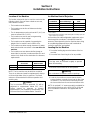
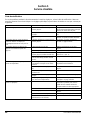
Ice Machine Heat of Rejection
* B.T.U./Hour
** Because the heat of rejection varies during the ice making cycle, the
figure shown is an average.
Ice machines, like other refrigeration equipment, reject
heat through the condenser. It is helpful to know the
amount of heat rejected by the ice machine when sizing
air conditioning equipment where self-contained air-
cooled ice machines are installed.
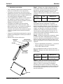
Leveling the Ice Machine
1. Screw the leveling legs onto the bottom of the ice
machine.
2. Screw the foot of each leg in as far as possible.
3. Move the ice machine into its final position.
4. Level the ice machine to assure that the siphon
system functions correctly. Use a level on top of the
ice machine. Turn each foot as necessary to level
the ice machine from front to back and side to side.
NOTE: An optional 2 ½" caster assembly is available for
use in place of the legs on the Q130, Q170, Q210 and
Q270. Installation instructions are supplied with the
casters.
Self-Contained
Air-Cooled
Self-Contained
Water-Cooled
Top/Sides 5" (127 mm)* 5" (127 mm)*
Back 5" (127 mm)* 5" (127 mm)*
!
Caution
The ice machine must be protected if it will be
subjected to temperatures below 32°F (0°C).
Failure caused by exposure to freezing
temperatures is not covered by the warranty. See
“Removal from Service/Winterization” Section 4.
Series
Ice Machine
Heat of Rejection*
Air Conditioning** Peak
Q130 2400 2900
Q170 2200 2600
Q210 2400 3400
Q270 3800 6000
!
Caution
The legs must be screwed in tightly to prevent
them from bending.
!
Warning
Do not obstruct ice machine vents or openings.

Installation Instructions Section 2
8
Part Number 040002380 9/12
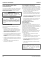
Electrical Service
GENERAL
VOLTAGE
The maximum allowable voltage variation is ± 10% of
the rated voltage on the ice machine model/serial
number plate at start-up (when the electrical load is
highest).
The 115/1/60 ice machines are factory pre-wired with a
8’ power cord, and NEMA 5-15P-plug configuration.
The 208-230/1/60 and 230/50/1 ice machines are
factory pre-wired with a 8’ power cord only, no plug is
supplied.
FUSE/CIRCUIT BREAKER
A separate fuse/circuit breaker must be provided for
each ice machine. Circuit breakers must be H.A.C.R.
rated (does not apply in Canada).
TOTAL CIRCUIT AMPACITY
The total circuit ampacity is used to help select the wire
size of the electrical supply.
The wire size (or gauge) is also dependent upon
location, materials used, length of run, etc., so it must be
determined by a qualified electrician.
GROUND FAULT CIRCUIT INTERRUPTER
Ground Fault Circuit Interrupter (GFCI/GFI) protection is
a system that shuts down the electric circuit (opens it)
when it senses an unexpected loss of power,
presumably to ground. Manitowoc Ice, Inc. does not
recommend the use of a GFCI/GFI circuit protection with
our equipment. If code requires the use of a GFCI/GFI
then you must follow the local code. The circuit must be
dedicated, sized properly and there must be a panel
GFCI/GFI breaker. We do not recommend GFCI/GFI
outlets as they are known for more intermittent nuisance
trips than panel breakers.
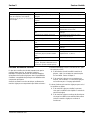
Q130/Q170/Q210/Q270 ICE MACHINE
!
Warning
All wiring must conform to local, state and national
codes.
!
Warning
The ice machine must be grounded in accordance
with national and local electrical codes.
!
Warning
PERSONAL INJURY POTENTIAL
If the supply cord is damaged, do not operate the
equipment until the cord is replaced by a service
agent or similarly qualified person.
Ice Machine Voltage
Phase
Cycle
Air-Cooled Water Cooled
Maximum Fuse/
Circuit Breaker
Total Amps Maximum Fuse/
Circuit Breaker
Total Amps
Q130 115/1/60 15 7.0 15 6.3
208-230/1/60 15 3.1 15 2.6
230/1/50 15 3.0 15 2.5
Q170 115/1/60 15 7.2 -- --
Q210
QP0210A
115/1/60 15 6.5 15 6.1
208-230/1/60 15 3.6 15 3.1
230/1/50 15 3.6 15 3.1
230/1/50 15 3.6*
Q270
Danfoss
Compressor
QP0270A
115/1/60 15 10.7 15 9.9
208-230/1/60 15 5.2 15 4.7
230/1/50 15 5.2 15 4.7
230/1/50 15 5.2* N/A N/A
Q270
Tecumseh
Compressor
115/1/60 15 8.5 15 7.7
208-230/1/60 15 4.5 15 4.0
230/1/50 15 4.5 15 4.0
* Indicates preliminary data

Section 2 Installation Instructions
Part Number 040002380 9/12 9
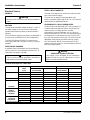
Water Service/Drains
WATER SUPPLY
Local water conditions may require treatment of the
water to inhibit scale formation, filter sediment, remove
chlorine, and improve taste and clarity.
WATER INLET LINES
Follow these guidelines to install water inlet lines:
• Do not connect the ice machine to a hot water
supply. Be sure all hot water restrictors installed for
other equipment are working. (Check valves on sink
faucets, dishwashers, etc.)
• If water pressure exceeds the maximum
(80 psig-551.5 kPA) recommended pressure, obtain
a water pressure regulator from your Manitowoc
distributor.
• Install a water shut-off valve and union for both the
ice making and condenser water lines.
• Insulate water inlet lines to prevent condensation.
DRAIN CONNECTIONS
Follow these guidelines when installing drain lines to
prevent drain water from flowing back into the ice
machine and storage bin:
• Drain lines must have a 1.5 inch drop per 5 feet of
run (2.5 cm per meter), and must not create traps.
• The floor drain must be large enough to
accommodate drainage from all drains.
• Run separate bin and water-cooled condenser drain
lines. Insulate them to prevent condensation.
• Vent the bin drain to the atmosphere. Do not vent the
condenser drain on water-cooled models.
COOLING TOWER APPLICATIONS
(Water-Cooled Models)
A water cooling tower installation does not require
modification of the ice machine. The water regulator
valve for the condenser continues to control the
refrigeration discharge pressure.
It is necessary to know the amount of heat rejection and
the pressure drop through the condenser and water
valves (inlet and outlet) when using a cooling tower on
an ice machine.
• Water entering the condenser must not exceed 90°F
(32°C).
• Water flow through the condenser must not exceed 5
gallons (19 liters) per minute.
• Allow for a pressure drop of 7 psi (48 kPA) between
the condenser water inlet and the outlet of the ice
machine.
• Water exiting the condenser must not exceed 110°F
(43°C).
Water Supply and Drain Line Sizing/Connections
!
Warning
PERSONAL INJURY POTENTIAL
For ice making, connect to a potable water supply
only.
Important
If you are installing a Manitowoc water filter
system, refer to the Installation Instructions
supplied with the filter system for ice making water
inlet connections.
Location Water
Temperature
Water
Pressure
Ice Machine
Fitting
Tubing Size Up to Ice
Machine Fitting
Ice Making
Water Inlet
40°F (4°C) Min.
90°F (32°C) Max.
20 psi (137.9 kPA) Min.
80 psi (551.5 kPA) Max.
3/8" Female Pipe
Thread
3/8" (9.5 mm) minimum
inside diameter
Condenser Water
Inlet
40°F (4°C) Min.
90°F (32°C) Max.
20 psi (137.9 kPA) Min.
150 psi (1034.2 kPA) Max.
3/8" Female Pipe
Thread
Q270 Only
1/2" Female Pipe
Thread
3/8" (9.5 mm) minimum
inside diameter
Q270 Only
1/2" (12.7 mm)
minimum inside diameter
Condenser Water
Drain
--- --- 1/2" Female Pipe
Thread
1/2" (12.7 mm) minimum
inside diameter
Bin Drain
--- --- 1/2" Female Pipe
Thread
1/2"” (12.7 mm) minimum
inside diameter

Installation Instructions Section 2
10
Part Number 040002380 9/12
Before Starting the Ice Machine
All Manitowoc ice machines are factory-operated and adjusted before shipment. Normally, new installations do not
require any adjustment.
To ensure proper operation, follow the Operational Checks in Section 3 of this manual. Starting the ice machine and
completing the Operational Checks are the responsibilities of the owner/operator.
Adjustments and maintenance procedures outlined in this manual are not covered by the warranty.
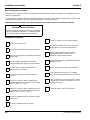
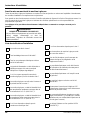
Installation Checklist
!
Warning
PERSONAL INJURY POTENTIAL
Do not operate equipment that has been misused,
abused, neglected, damaged, or altered/modified
from that of original manufactured specifications.
Is the ice machine level?
Has all of the internal packing been removed?
Have all of the electrical and water connections
been made?
Has the supply voltage been tested and
checked against the rating on the nameplate?
Is there proper clearance around the ice
machine for air circulation?
Is the ice machine grounded and polarity
correct?
Has the ice machine been installed where
ambient temperatures will remain in the range
of 40° – 110°F (4° – 43°C)?
Has the ice machine been installed where the
incoming water temperature will remain in the
range of 40° – 90°F (4° – 32°C)?
Is there a separate drain for the water-cooled
condenser?
Is there a separate drain for the bin?
Are the ice machine and bin drains vented?
Are all electrical leads free from contact with
refrigeration lines and moving equipment?
Has the owner/operator been instructed
regarding maintenance and the use of
Manitowoc Cleaner and Sanitizer?
Has the owner/operator completed the warranty
registration card?
Has the ice machine and bin been sanitized?
Is the toggle switch set to ice? (The toggle
switch is located directly behind the front panel).
Is the ice thickness control set correctly? (Refer
to Operational Checks to check/set the correct
ice bridge thickness).
Is the float valve in the OPEN position?

Section 3 Operation
Part Number 040002380 9/12 11
Section 3
Operation
Ice Making Sequence of Operation
INITIAL START-UP OR START-UP AFTER
AUTOMATIC SHUT-OFF
1. Pressure Equalization
Before the compressor starts the hot gas valve is
energized for 15 seconds to equalize pressures during
the initial refrigeration system start-up.
2. Refrigeration System Start-Up
The compressor starts after the 15-second pressure
equalization, and remains on throughout the entire
Freeze and Harvest Sequences. The hot gas valve
remains on for 5 seconds during initial compressor start-
up and then shuts off.
At the same time the compressor starts, the condenser
fan motor (air-cooled models) is supplied with power
throughout the entire Freeze and Harvest Sequences.
The fan motor is wired through a fan cycle pressure
control, therefore it may cycle on and off. (The
compressor and condenser fan motor are wired through
the relay. As a result, any time the relay coil is energized,
the compressor and fan motor are supplied with power.)
FREEZE SEQUENCE
3. Prechill
The compressor energizes to prechill the evaporator
prior to water flow.
4. Freeze
The water pump starts after the Prechill. An even flow of
water is directed across the evaporator and into each
cube cell, where it freezes.
When sufficient ice has formed, the water flow (not the
ice) contacts the ice thickness probe. After
approximately 7 seconds of continual water contact, the
Harvest Sequence is initiated. The ice machine cannot
initiate a Harvest Sequence until a 6-minute freeze time
has been surpassed.
HARVEST SEQUENCE
5. Harvest
The water pump de-energizes stopping flow over the
evaporator. The rising level of water in the sump trough
diverts water out of the overflow tube, purging excess
minerals from the sump trough. The hot gas valve also
opens to divert hot refrigerant gas into the evaporator.
The refrigerant gas warms the evaporator causing the
cubes to slide, as a sheet, off the evaporator and into the
storage bin. The sliding sheet of cubes contacts the ice
damper, opening the bin switch.
The momentary opening and re-closing of the bin switch
terminates the Harvest Sequence and returns the ice
machine to the Freeze Sequence (steps 3 - 4).
AUTOMATIC SHUT-OFF
6. Automatic Shut-Off
When the storage bin is full at the end of a Harvest
Sequence, the sheet of cubes fails to clear the ice
damper and will hold it down. After the ice damper is
held open for 7 seconds, the ice machine shuts off. The
ice machine remains off for 3 minutes before it can
automatically restart.
The ice machine remains off until enough ice has been
removed from the storage bin to allow the ice to fall clear
of the damper. As the ice damper swings back to the
operating position, the bin switch re-closes and the ice
machine restarts (steps 1 - 2), provided the 3-minute
delay period is complete.

Operation Section 3
12
Part Number 040002380 9/12
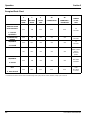
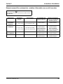
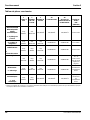
Energized Parts Chart
* Condenser Fan Motor: The fan motor is wired through a fan cycle pressure control, therefore, it may cycle on and off.
CONTROL BOARD RELAYS RELAY
1 2 3 3A 3B
LENGTH
WATER
PUMP
HOT GAS
VALVE
RELAY
COIL
COMPRESSOR CONDENSER ∗
FAN MOTOR
of “ON”
TIME
INITIAL START-UP/
START UP AFTER
AUTO SHUT-OFF:
1. Pressure
Equalization
OFF ON OFF OFF OFF
15
Seconds
2. Refrigeration
System Start-up
OFF ON ON ON ON
5
Seconds
FREEZE
SEQUENCE:
3. Pre-Chill
OFF OFF ON ON ON
30
Seconds
4. Freeze
ON OFF ON ON ON
Until 7 sec.
water contact
with ice
thickness
probe
HARVEST
SEQUENCE:
5. Harvest
OFF ON ON ON ON
Bin switch
activation
AUTOMATIC SHUT-
OFF:
6. Auto Shut-Off
OFF OFF OFF OFF OFF
Until
bin switch
re-closes

Section 3 Operation
Part Number 040002380 9/12 13
Operational Checks
GENERAL
Your Manitowoc ice machine was factory-operated and
adjusted before shipment. Normally, a newly installed ice
machine does not require any adjustment.
To ensure proper operation, always follow these
Operational Checks when starting the ice machine:
• for the first time
• after a prolonged out of service period
• after cleaning and sanitizing
Routine adjustments and maintenance procedures
outlined in this manual are not covered by the warranty.
SIPHON SYSTEM
To reduce mineral build-up and cleaning frequency, the
water in the sump trough must be purged during each
harvest cycle.
When the water pump de-energizes the level in the
water trough rises above the standpipe starting a siphon
action. The siphon action stops when the water level in
the sump trough drops. When the siphon action stops,
the float valve refills the water trough to the correct level.
Siphon System Check
Follow steps 1 through 6 under water level check.
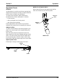
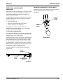
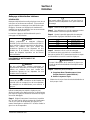
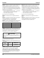
WATER FLOAT VALVE CHECK
Before water will flow into the water trough the float
valve shut-off must be in the OPEN position.
Water Level
WATER
LEVEL
SIPHON
CAP
STANDPIPE
DRAIN
PRESS TO
OPEN
PRESS TO
CLOSE

Operation Section 3
14
Part Number 040002380 9/12
WATER LEVEL CHECK
Check the water level while the ice machine is in the ice
mode and the water pump is running. The correct water
level is 1/4" (6.3mm) to 3/8" (9.5mm) below the top of
the standpipe a line in the water trough indicates the
correct level.
Water Level
The float valve is factory-set for the proper water level. If
adjustments are necessary:
1. Verify the ice machine is level (see page 2-4).
2. Remove the siphon cap from the standpipe.
3. Place the main ON/OFF/WASH toggle switch to the
ON position, and wait until the float valve stops
adding water.
4. Adjust the water level to (1/4" to 3/8" (6.3 to 9.5 mm)
below the standpipe) the line in the water trough:
5. Loosen the two screws on the float valve bracket.
6. Raise or lower the float valve assembly as
necessary, then tighten the screws.
7. Move the main ON/OFF/ WASH toggle switch to the
OFF position. The water level in the trough will rise
above the standpipe and run down the drain.
8. Replace the siphon cap on the standpipe, and verify
water level and siphon action by repeating steps 3
through 5.
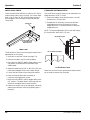
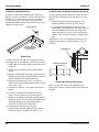
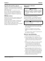
ICE BRIDGE THICKNESS CHECK
The ice thickness probe is factory-set to maintain the ice
bridge thickness at 1/8" (3.2 mm).
1. Inspect the bridge connecting the cubes. It should
be about 1/8" (3.2 mm) thick.
2. If adjustment is necessary, turn the ice thickness
probe adjustment screw clockwise to increase
bridge thickness, or counterclockwise to decrease
bridge thickness.
NOTE: Turning the adjustment 1/3 of a turn will change
the ice thickness about 1/16" (1.5 mm).
Ice Thickness Check
Make sure the ice thickness probe wire and the bracket
do not restrict movement of the probe.
SIPHON CAP
SET THE WATER LEVEL
TO THE LINE IN THE
WATER TROUGH
ADJUSTING SCREW
1/8" ICE BRIDGE THICKNESS

Section 4 Maintenance
Part Number 040002380 9/12 15
Section 4
Maintenance
Interior Cleaning and Sanitizing
GENERAL
Clean and sanitize the ice machine every six months for
efficient operation. If the ice machine requires more
frequent cleaning and sanitizing, consult a qualified
service company to test the water quality and
recommend appropriate water treatment.
The ice machine must be taken apart for cleaning and
sanitizing.
CLEANING AND SANITIZING PROCEDURE
Ice machine cleaner is used to remove lime scale and
mineral deposits. Ice machine sanitizer disinfects and
removes algae and slime.
Step 1 Set the toggle switch to the OFF position after
ice falls from the evaporator at the end of a Harvest
cycle. Or, set the switch to the OFF position and allow
the ice to melt off the evaporator.
Step 2 Remove all ice from the bin.
Step 3 To start a cleaning cycle, move the toggle switch
to the WASH position.
Step 4 Add the proper amount of Manitowoc Ice
Machine Cleaner to the water trough.
Step 5 Wait until the clean cycle is complete
(approximately 22 minutes) then place the toggle switch
in the OFF position, disconnect power and water
supplies to the ice machine.
!
Caution
Use only Manitowoc approved Ice Machine Cleaner
(part number 94-0546-3) and Sanitizer (part
number 94-0565-3). It is a violation of Federal law
to use these solutions in a manner inconsistent with
their labeling. Read and understand all labels
printed on bottles before use.
!
Caution
Do not mix Ice Machine Cleaner and Sanitizer
solutions together. It is a violation of Federal law to
use these solutions in a manner inconsistent with
their labeling.
!
Warning
Wear rubber gloves and safety goggles (and/or face
shield) when handling Ice Machine Cleaner or
Sanitizer.
!
Caution
Never use anything to force ice from the evaporator.
Damage may result.
Model Amount of Cleaner
Q130 1 ounce (30 ml)
Q170 2 ounces (60 ml)
Q210 2 ounces (60 ml)
Q270 2 ounces (60 ml)
!
Warning
Disconnect electric power to the ice machine at the
electric switch box before proceeding.

Maintenance Section 4
16
Part Number 040002380 9/12
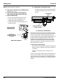
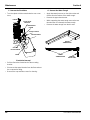
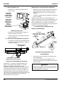
Step 6 Remove parts for cleaning.
A. Remove Two Thumbscrews and Water Pump
Cover (When Used).
B. Remove the Vinyl Hose Connecting the
Water Pump and Water Distribution Tube
C. Remove Water Pump
• Disconnect the water pump power cord
• Loosen the screws securing the pump-
mounting bracket to the bulkhead
• Lift the pump and bracket assembly off the
mounting screws..
Water Pump Removal
D. Remove the Ice Thickness Probe
• Compress the side of the ice thickness probe
near the top hinge pin and remove it from the
bracket.
Ice Thickness Probe Removal
NOTE: At this point, the ice thickness probe can easily
be cleaned. If complete removal is desired follow the ice
thickness probe wire to the bulkhead grommet (exit
point) in the back wall. Pop the bulkhead grommet out of
the back wall by inserting fingernails or a flat object
between the back wall and the grommet and prying
forward. Pull the bulkhead grommet and wire forward
until the connector is accessible, then disconnect the
wire lead from the connector.
Ice Thickness Probe Cleaning
• Mix a solution of Manitowoc ice machine cleaner and
water (2 ounces of cleaner to 16 ounces of water) in
a container.
• Soak the ice thickness probe a minimum of 10
minutes.
Clean all ice thickness probe surfaces and verify the ice
thickness probe cavity is clean. Rinse thoroughly with
clean water, then dry completely. Incomplete rinsing and
drying of the ice thickness probe can cause premature
harvest.
DO NOT SOAK
WATER PUMP MOTOR IN
CLEANER OR SANITIZER
SOLUTIONS
When Used - REMOVE
THUMBSCREWS AND
WATER PUMP COVER
ICE THICKNESS
PROBE
COMPRESS SIDES OF ICE
THICKNESS PROBE

Section 4 Maintenance
Part Number 040002380 9/12 17
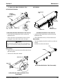
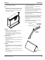
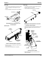
E. Remove the Water Distribution Tube
Q170/Q210/Q270 Models
Q170/Q210/Q270 Water Distribution Tube Removal
• Loosen the two thumbscrews, which secure the
distribution tube.
• Lift the right side of the distribution tube up off the
locating pin, then slide it back and to the right.
Disassembly
• Twist both of the inner tube ends until the tabs line up
with the keyways.
• Pull the inner tube ends outward.
Q170/Q210/Q270 Water Distribution Tube
Disassembly
Q130 Models
Q130 Water Distribution Tube Removal
• Loosen the two thumbscrews, which secure the
distribution tube.
• Lift the distribution tube up off the thumbscrews.
Disassembly
• Twist the barbed end until the tab lines up with the
keyway.
• Pull the inner tube end outward.
Q130 Water Distribution Tube Disassembly
!
Caution
Do not force this removal. Be sure the locating pin is
clear of the hole before sliding the distribution tube
out.
1. LIFT UP
2. SLIDE BACK
3. SLIDE TO RIGHT
DISTRIBUTION
TUBE
THUMBSCREW
THUMBSCREW
LOCATING
PIN
3
2
1
INNER TUBE
TAB
KEYWAY
INNER TUBE
THUMBSCREW
REMOVE ICE
THICKNESS PROBE
THUMBSCREW
DISTRIBUTION
TUBE
TAB
KEYWAY

Maintenance Section 4
18
Part Number 040002380 9/12
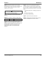
F. Remove the Float Valve
• Turn the splash shield counterclockwise one or two
turns.
Float Valve Removal
• Pull the float valve forward and off the mounting
bracket.
• Disconnect the water inlet tube from the float valve at
the compression fitting.
• Remove the cap and filter screen for cleaning.
G. Remove the Water Trough
• Apply downward pressure on the siphon tube and
remove from the bottom of the water trough.
• Remove the upper thumbscrew.
• While supporting the water trough remove the two
thumbscrews from beneath the water trough.
• Remove the water trough from the bin area.
FLOAT VALVE
BRACKET
COMPRESSION
FITTING
CAP AND
FILTER SCREEN
SHUT-OFF VALVE
SPLASH SHIELD
FLOAT
REMOVE
SIPHON TUBE
UPPER
THUMBSCREW
LOWER
THUMBSCREWS

Section 4 Maintenance
Part Number 040002380 9/12 19
H. Remove the ice damper.
Q130
• Grasp left side of ice damper and apply pressure
against the right-hand ice damper mounting bracket.
• Pull forward on the ice damper until the left-hand
mounting pin disengages.
Installation
• Grasp the right side of ice damper and place left
hand pin in the mounting bracket.
• While applying pressure against the left-hand
mounting bracket push the damper until the right-
hand mounting pin engages.
Q170/Q210/Q270
• Grasp ice damper and apply pressure toward the left
hand mounting bracket.
• Apply pressure to the right hand mounting bracket
with thumb.
• Pull ice damper forward when the right hand ice
damper pin disengages.
Installation
• Place ice damper pin in left hand mounting bracket
and apply pressure toward the left hand mounting
bracket.
• Apply pressure to the right hand mounting bracket
with thumb.
• Push ice damper toward evaporator until right hand
damper pin engages.
I. Remove the Bin Door
• Grasp the rear of the bin door and pull bin door
forward approximately 5".
• Slide bin door to the rear while applying upward
pressure (The rear door pins will ride up into the track
slot and slide backward to the stop tab).
• While applying pressure against the bin door pull
down on the rear of each bin door track until the door
pins clear the stop tabs.
• Slide the rear door pins off the end and then below
the door track. Slide bin door forward allowing the
back of the door to lower into the bin. Continue
forward with the bin door until the front pins bottom
out in the track.
• Lift right side of door until the front pins clear the
track, then remove door from bin.
• Remove rollers (4) from all door pins.
TRACK SLOT
SLIDE DOOR
FORWARD
STOP TAB
PRESS DOWN TO
RELEASE DOOR
ROLLER

Maintenance Section 4
20
Part Number 040002380 9/12
Step 7 Mix a solution of cleaner and warm water.
Depending on the amount of mineral buildup, a larger
quantity of solution may be required. Use the ratio in the
table below to mix enough solution to thoroughly clean
all parts.
Step 8 Use ½ of the cleaner/water solution to clean all
components. The cleaner solution will foam when it
contacts lime scale and mineral deposits; once the
foaming stops use a soft bristle brush, sponge or cloth
(not a wire brush) to carefully clean the parts. Soak the
parts for 5 minutes (15 – 20 minutes for heavily scaled
parts). Rinse all components with clean water.
Step 9 While components are soaking, use ½ of the
cleaner/water solution to clean all foodzone surfaces of
the ice machine and bin. Use a nylon brush or cloth to
thoroughly clean the following ice machine areas:
• Evaporator plastic parts – including top, bottom and
sides
• Bin bottom, sides and top
Rinse all areas thoroughly with clean water.
Step 10 Mix a solution of sanitizer and warm water.
Step 11 Use 1/2 of the sanitizer/water solution to
sanitize all removed components. Use a cloth or sponge
to liberally apply the solution to all surfaces of the
removed parts or soak the removed parts in the
sanitizer/water solution. Do not rinse parts after
sanitizing.
Step 12 Use 1/2 of the sanitizer/water solution to
sanitize all foodzone surfaces of the ice machine and
bin. Use a cloth or sponge to liberally apply the solution.
When sanitizing, pay particular attention to the following
areas:
• Evaporator plastic parts - including top, bottom and
sides
• Bin bottom, sides and top
Do not rinse the sanitized areas.
Step 13 Replace all removed components.
Step 14 Reapply power and water to the ice machine
and place the toggle switch in the WASH position.
Step 15 Add the proper amount of Manitowoc Ice
Machine Sanitizer to the water trough.
Solution Type Water Mixed with
Cleaner 1 gal. (4 l) 16 oz (500 ml) cleaner
Solution Type Water Mixed With
Sanitizer 6 gal. (23 l) 4 oz (120 ml) sanitizer
Model Amount of Sanitizer
Q130 1.6 ounces (48 ml)
Q170 2.2 ounces (66 ml)
Q210 2.2 ounces (66 ml)
Q270 1.9 ounces (57 ml)
La page est en cours de chargement...
La page est en cours de chargement...
La page est en cours de chargement...
La page est en cours de chargement...
La page est en cours de chargement...
La page est en cours de chargement...
La page est en cours de chargement...
La page est en cours de chargement...
La page est en cours de chargement...
La page est en cours de chargement...
La page est en cours de chargement...
La page est en cours de chargement...
La page est en cours de chargement...
La page est en cours de chargement...
La page est en cours de chargement...
La page est en cours de chargement...
La page est en cours de chargement...
La page est en cours de chargement...
La page est en cours de chargement...
La page est en cours de chargement...
La page est en cours de chargement...
La page est en cours de chargement...
La page est en cours de chargement...
La page est en cours de chargement...
La page est en cours de chargement...
La page est en cours de chargement...
La page est en cours de chargement...
La page est en cours de chargement...
La page est en cours de chargement...
La page est en cours de chargement...
-
 1
1
-
 2
2
-
 3
3
-
 4
4
-
 5
5
-
 6
6
-
 7
7
-
 8
8
-
 9
9
-
 10
10
-
 11
11
-
 12
12
-
 13
13
-
 14
14
-
 15
15
-
 16
16
-
 17
17
-
 18
18
-
 19
19
-
 20
20
-
 21
21
-
 22
22
-
 23
23
-
 24
24
-
 25
25
-
 26
26
-
 27
27
-
 28
28
-
 29
29
-
 30
30
-
 31
31
-
 32
32
-
 33
33
-
 34
34
-
 35
35
-
 36
36
-
 37
37
-
 38
38
-
 39
39
-
 40
40
-
 41
41
-
 42
42
-
 43
43
-
 44
44
-
 45
45
-
 46
46
-
 47
47
-
 48
48
-
 49
49
-
 50
50


Manitowoc Q Model Undercounter Guide d'installation
- Catégorie
- Fabricants de glaçons
- Taper
- Guide d'installation
- Ce manuel convient également à
dans d''autres langues
Documents connexes
-
Manitowoc Q170 Mode d'emploi
-
Manitowoc Ice QM45 Undercounter Guide d'installation
-
-
-
-
-
-
-
Indigo ID0853W Le manuel du propriétaire