SportsArt A989 Le manuel du propriétaire
- Taper
- Le manuel du propriétaire

Sports Art Industrial Co., Ltd. TUV-CERT ISO 9001/9002/14000 Certifi ed Quality Products 2013.01
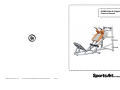
A989 Hack Squat
Owner’s Manual

A989 OWNER’S MANUAL CONTENTS
1. INTRODUCTION ................................................................................ 2
2. SAFETY PRECAUTIONS .................................................................. 3
3. LIST OF PARTS ................................................................................. 4
4. ASSEMBLE THE PRODUCT ............................................................. 6
STEP 1 Assemble the Main Components .............................................. 6
STEP 2 Install the Cushions and Handles ............................................ 9
STEP 3 Install the Weight Plate Pegs .................................................. 11
STEP 4 Level the Unit ........................................................................... 12
5. OPERATE THE PRODUCT ............................................................... 13
OPERATION Placement Settings .......................................................... 13
OPERATION Operate the Product ........................................................ 14
6. MAINTENANCE ................................................................................ 15
MAINTENANCE Glide Rail Cleaning ................................................... 15
MAINTENANCE Schedule .................................................................... 16
MAINTENANCE Task List .................................................................... 17
MAINTENANCE One-Year Maintenance Log ....................................... 18
7. CONSIGNES DE SÉCURITÉ IMPORTANTES ................................. 19

2
1. INTRODUCTION
Congratulations on the purchase of a high quality SportsArt product, the A989 hack
squat machine. Constructed of high quality materials and designed for years of
reliable performance, this product was made for full commercial use.
Before this product is assembled or operated, we recommend that you familiarize
yourself with this manual. Understanding the correct assembly and operation of
this product will help ensure that exercisers obtain their tness goals safely and
successfully.

3
2. SAFETY PRECAUTIONS
This product was designed and built for optimum safety. However certain precau-
tions apply during the use of this product. Please note the following safety
precautions:
• Please read the entire manual before assembly and operation. Make
sure the product is installed and operated as instructed in this manual.
• Assemble and operate the product on a solid, level surface. Do not use
outdoors or near water, including pools and saunas.
• Check the product before every use. Make sure all parts are assem-
bled, and all fasteners are tightened. Do not use the product if it is disas-
sembled in any way.
• Wear proper workout clothing. Do not wear loose clothing. Do not wear
shoes with leather soles or high heels. Tie all long hair back. Do not go
barefoot on this product.
• Keep away from moving parts. Moving parts may or may not stop imme-
diately if an object becomes caught or impedes normal motion.
• Use this product only for its intended purpose as described in this
manual.
• Be careful when mounting and dismounting the unit.
• Never operate this product if it has been damaged in any way. If it is
not working properly, or has been dropped or damaged, contact a service
technician for repairs.
• Do not use accessories that are not specically recommended by the
manufacturer. Such parts might cause injuries or cause the unit to fail.
• This product is not intended for use by persons (including children) with
reduced physical, sensory, or mental capabilities, or by people who are
otherwise decient in product knowlege or experience. If such people use
this product, they should be given training and be supervised at all times
by someone responsible for their safety.
• Children should be supervised to ensure that they do not play on or
near the product.
• The user weight limit for this product is 227 kg, 500 lb.
CAUTION: If you feel any pain or any abnormal sensations, STOP YOUR
WORKOUT and consult your physician immediately. Work within your rec-
ommended exercise level. DO NOT work to exhaustion. Before beginning any
exercise program, you should consult with your doctor. It is recommended that you
undergo a complete physical examination.

4
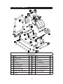
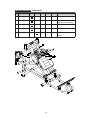
3. LIST OF PARTS
Assembly Parts
No. Name Qty. No. Name Qty.
A1 Upright frame 1 A9 Cover 2
A2 Base 1 A10 Security clip 2
A3 Link tube 1 A11 Cover set plate 2
A4
Connector plate
4 A12
Clip
1
A5 Inclined frame 1 A13 Lower left bracket tube 1
A6 Weight plate peg 4 A14 Lower right bracket tube 1
A7 Weight plate peg (long) 2 A15 Connector plate 2
A8 Handle 2

5
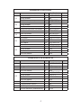
Components on the Product
No. Name Qty. Specication Notes
31
Mushroom top inner hex screw 8 M8*P1.25*L20
Spring washer 8 M8
Flat washer 8 D22*d8.2*t2
32
Mushoom top inner hex screw 8 M8*P1.25*L20
Spring washer 8 M8
Handle washer 8 D18*d8.5*t2
33
Mushroom top inner hex screw 16 M6*P1.00*L15
Handle washer 16 D20*d7*t2.0
34
Inner hex screw 13 M5*P0.8*L15
Flat washer 13 D16*d6.3*t2
35
Hex screw 6 M10*P1.5*L30
Spring washer 6 M10
Flat washer 12 D21*d10.5*t2
Hex lock nut 6 M10
36
Hex nut 4 M10*P1.5*L30
Spring washer 4 M10
Flat washer 8 D21*d10.5*t2
Hex lock washer 4 M10
Components in the Hardware Kit
No. Name Qty. Specication Notes
41 Hex screw 8 M10*P1.5*L130
Spring washer 8 M10
Washer 16 D16*d10.2*t1.0
Hex lock washer 8 M10
42
Hex screw 4 M10*P1.5*L75
Spring washer 4 M10*t1.0
Flat washer 8 M16*d10.2*t1
Hex lock washer 4 M10
L-shaped Allen wrench 1 M6
L-shaped Allen wrench 1 M4
Double open-end wrench 2 13*17
Silicone lubricant (maintenance) 1 50 cc

6
4. ASSEMBLE THE PRODUCT
Follow instructions below to assemble this product. Note that in this manual
the words “left” and “right” are used to refer to the product and its parts. As
such, these designations correspond to the “left” and “right” sides of a person
in position to exercise on this product. Also, for brevity, the word “screws” is
used where screws, washers, and other hardware may be involved.
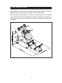
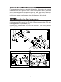
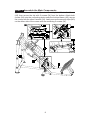
STEP 1 Assemble the Main Components
Please follow instructions (a) through (d) to assemble the main components.
(a) Use screws (41) to secure the link tube (A3) and connector plate (A4) onto
the upright frame (A1) and base (A2).
(b) Hold the inclined frame (A5) onto the base (A2), and loosely secure
screws (34,35).

7
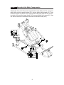
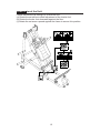
STEP 1 Assemble the Main Components (Continued)
(c) First remove the screws (36) from upright frame (A1). In area (A), align the
holes of the inclined frame (A5) with the top of the upright frame (A1), then
loosely secure both frames with the screws (36). In area (B), align the holes
of the bottom of the incline frame (A5) with the base frame (A2), then tighten
the screws (35). Lastly, tighten the screws (36) in area (A).

8
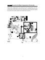
STEP 1 Assemble the Main Components
(d) In area B, Insert the clip (A12) under the metal plate of the inclined frame
(A5), then secure the clip with 3 screws (34) from the bottom. Attach both
covers (A9) onto the connecting plate under the Inclined frame (A5), secure
the covers with the other 8 screws (34). Lastly, secure the security clips (A10)
on the either side of the covers with the remaining 2 screws (34).

9
STEP 1 Assemble the Main Components
Assemble the bracket tubes
Attach the front end of the lower right bracket tube (A14) and the connector
plate (A4) onto the upright frame (A1), secure tightly with screws (41). Then
attach the back end of the lower right bracket tube (A14) and the the connec-
tor plate (A4) onto the base frame (A2), secure tightly with screw (41). Use
the same methods to assemble the lower left bracket tube (A13)

10
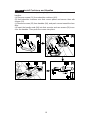
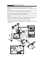
STEP 2 Install Cushions and Handles
Please follow instructions (a) through (d) to install shoulder cushions and
handles.
(a) Remove screws (31) from shoulder cushions (A11).
(b) Hold shoulder cushions onto their mount plates and secure then with
screws (31).
(c) Remove screws (32) from handles (A8), and push covers toward the han-
dles.
(d) Insert the handle ends (A8) into their mounts, and use screws (32) to se-
cure the handles. Then push the covers into place.

11
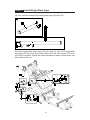
STEP 3 Install Weight Plate Pegs
Please follow instructions (a) through (b) to install weight plate pegs.
(a) First, remove screws from weight plate pegs (A6) and (A7).
(b) Insert weight plate short pegs (A6) into area (A). Insert the weight plate
long pegs (A7) into area (B) on both sides of the unit. Use screws (33) to se-
cure them into place. Follow the same procedure to secure these parts onto
both sides of the unit.

12
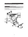
STEP 4 Level the Unit
Follow instructions (a) through (c) to level the unit.
(a) Rotate the set screw to allow adjustment of the leveler foot.
(b) Rotate the leveler foot downward against the floor.
(c) Rotate the set screw upward against the frame to secure this position.

13
5. OPERATE THE PRODUCT
This section includes operational instructions.
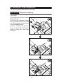
OPERATION Placement Settings
Follow instructions (a) through (c) below to establish placement settings for
your height.
(a) Push the inclined frame upward
and hold it there.
(b) Press the placement setting
lever downward, making the hook
rise. Then slide the inclined frame
into the desired position.
(c) After checking the position,
press the placement setting lever
upward, making the hook latch
into place.

14
OPERATION Operate the Product
(a) Select the appropriate weight plates placed on both sides of the weight
plate pegs, and then secure the weight plates with safety clamps.
(b) Open foot stance slightly wider than shoulder width, perpendicular to the
foot mat.
(c) Lay back flat on the back support cushion, keep shoulder secure under
the shoulder cushion with straight posture while excercising.
(d) Once ready to excercise, raise the back support cushion while extending
both legs, and then release the positioning handles.
(e) Inhale while the extending legs straight, exhale slowly back to the original
position.
*Note: While operating the machine, if the weight plate is moving around.
Please stop immediately, re-position the weight plate before continue.
* Weight limit: weight plate limit of 400Kg (unilateral 200Kg)
* Please excercise within the range of your skill and training.
* Operate this machine must be supervised under coaches instructions in
order for safety.

15
6. MAINTENANCE
This section covers maintenance topics, including glide rail cleaning, a
schedule, a list of tasks, and a page for record keeping.
MAINTENANCE Glide Rail Cleaning
Please follow instructions below to clean glide rails every day.
(a) Use a clean, lint-free cloth to wipe clean the glide rails on which the in-
clined frame slide.
(b) Test the operation of the inclined frame to ensure good movement.
(c) Repeat steps (a) and (b) two or three times.

16
MAINTENANCE Schedule
Area Day Week Month Quarter Year Notes
1 Exterior Clean.
2 Screws Inspect for looseness
and secure if necessary.
3 Cushions Wipe with a damp cloth.
4 Glide rails Wipe clean with a cloth.
5 Rollers Apply lubricant and spin
rollers.

17
MAINTENANCE Task List
Like cars, fitness products require maintenance. Regular maintenance ex-
tends product life, and failure to maintain products can void the manufac-
turer’s warranty. Copy the maintenance log sheet, and record maintenance
work for each fitness product.
Daily tasks
1. Use a clean, lint-free towel to wipe down the product exterior.
2. Inspect all screws. Secure if necessary.
3. Wipe cushions clean with a damp cloth.
4. Wipe glide rails clean with a cloth.
Weekly tasks
1. Apply lubricant to the rollers, and spin them to let the lubricant disperse.
Caution
● Please follow standard safety precautions when working on this product.
● Do NOT use cleaners with alcohol, ammonia, or other damaging chemi-
cals. The use of such chemicals can damage the product and void the war-
ranty. Never spray or pour any liquid directly onto the product. Doing so can
damage components and void the warranty.

18
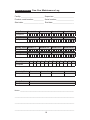
Daily Tasks Weeks 1-7 Weeks 8-14 Weeks 15-21 Week 22-28
Completed
Daily Tasks Week 29-35 Week 36-42 Week 43-49 Week 50-52
Completed
Weekly Tasks Weeks 1-7 Weeks 8-14 Weeks 15-21 Weeks 22-28
Completed
Weekly Tasks Weeks 29-35 Weeks 35-42 Weeks 43-49 Weeks 50-52
Completed
Monthly tasks 1 2 3 4 5 6 7 8 9 10 11 12
Completed
Quarterly Tasks Quarter 1 Quarter 2 Quarter 3 Quarter 4
Completed
Yearly Tasks Year 1
Completed
Notes: __________________________________________________________
________________________________________________________________
________________________________________________________________
________________________________________________________________
MAINTENANCE One-Year Maintenance Log
Facility:_______________________ Supervisor:____________________
Product model number:__________ Serial number:_________________
Start date: ____________________ End date:_____________________

19
7. CONSIGNES DE SÉCURITÉ IMPORTANTES
Le produit SportsArt a été conçu et fabriqué afin d’assurer une sécurité optimale.
Cependant certaines précautions s’appliquent chaque fois que vous utilisez votre
produit.
• Lisez entièrement le manuel avant l’assemblage et l’utilisation. Veuillez aussi
noter les consignes de sécurité suivantes:
• Veuillez lire attentivement les instructions et installer le produit selon les in-
structions.
• Assemblez et faites fonctionner le produit sur une surface solide et plane; NE
PAS l’utiliser à l’extérieur ou près de l’eau.
• En aucun cas, ne laissez des enfants à proximité ou sur le produit.
• Vériez le tapis de course avant chaque utilisation. Assurez-vous que toutes
les pièces sont assemblées et que tous les éléments de xation sont serrés. NE
PAS utiliser le produit si l’appareil est démonté de quelque façon.
• Gardez vos mains loin des pièces mobiles.
• Portez des vêtements d’entraînement appropriés; NE PORTEZ PAS de vête-
ments amples. NE PORTEZ PAS de chaussures à semelles en cuir ou à talons
hauts. Attachez les cheveux longs.
• Soyez prudent lors du montage et démontage de l’appareil.
• NE PAS utiliser d’accessoire non spéciquement recommandé par le fabri-
cant. Car cela pourraient provoquer des blessures ou entraîner une panne de
l’appareil.
• Débranchez l’appareil de la prise avant l’entretien ou la suppression de toute
pièce.
• Une surveillance étroite est nécessaire quand de produit est utilisé par ou à
proximité d’enfants, de malades ou de personnes handicapées.
• Utilisez ce product uniquement pour l’usage prévu dans ce manuel.
• La limite de poids de l’utilisateur pour le produit est de 227 kg, 500 lb.
• Ce produit n’est pas destiné à être utilisé par des personnes (y compris des
enfants) dont les capacités physiques, sensorielles ou mentales sont réduites ou
qui ne disposent pas de l’expérience ou du savoir nécessaires, sauf si celles-ci
ont au préalable été formées eu égard à l’utilisation de produit par une personne
responsable de leur sécurité.
• Les enfants doivent être encadrés an d’empêcher qu’ils ne jouent avec le
produit.
La page est en cours de chargement...
-
 1
1
-
 2
2
-
 3
3
-
 4
4
-
 5
5
-
 6
6
-
 7
7
-
 8
8
-
 9
9
-
 10
10
-
 11
11
-
 12
12
-
 13
13
-
 14
14
-
 15
15
-
 16
16
-
 17
17
-
 18
18
-
 19
19
-
 20
20
-
 21
21


SportsArt A989 Le manuel du propriétaire
- Taper
- Le manuel du propriétaire
dans d''autres langues
- English: SportsArt A989 Owner's manual
Documents connexes
-
SportsArt A982 Le manuel du propriétaire
-
-
-
-
-
-
-
-
-