Kenmore Elite 625385200 Guide d'installation
- Taper
- Guide d'installation

Installation Instructions
Instrucciones de Instalaci6n
Instructions d'installation
English / Espaffol / Fran_:ais
Models / Moclelos / ModUles
625.385200
625.75590
For a detailed Use and Care Guide, including
specifications, programming and parts list, go to:
www.sears.com (U.S.A.) www.sears.ca (Canada)
or call the Kenmore Water Line at
1-800-426-9345
Para obtener el manual detellado de us@y
cuidado, con especificaciones, programaci6n
y lista de piezas, visite el sitio:
www.sears.com (Estados Unidos) www.sears.ca (Canad6)
o Ilame a la linea directa de Kenmore Water al
1-800-426-9345
Pour obtenir un guide d6taill6 d'utilisation
et d'entretien, y compris les sp6cifications,
la programmation, et la liste des pi_ces, visitez :
www.sears.com (l_tats-Unis) www.sears.ca (Canada)
ou appelez la ligne d'assistance de Kenmore au
1-800-426-9345
I(enrnore Elite
@
A w_"lllll'e_sof"lllll'ene_ _nd _ whe_e home fiPlllll'e_in one
° Agu_
Un ab_andador de agua con fHff@ in_egrad@ para toda _a casa
@ @
A _® lois ®deu¢[sseur d_e_u et sysf6_e de filtration centr®_
Sears Brands Management Corporation
3333 Beverly Road
Hoffman Estates, IL 60179 U.S.A
www.kenmorewater.com
www.kenmore.com
www.sears.com
Sears Canada Inc.
290 Yonge Street
Toronto, Ontario M5B 2C3 Canada
www.sears.ca
IIIIIIIIIIIIIIIIIIIIIIIIIIIIIIIIIIIIIIIIIIIII
P/N 7338276 (Rev. D 7/22/14)

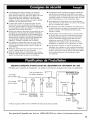
WARRANTY ON KENMORE ELITE®HYBRID WATER SOFTENER
ONE YEAR LIMITED WARRANTY ON HYBRID WATER SOFTENER
When installed, operated and maintained according to all instructions supplied with the product, if this
Kenmore appliance fails due to a defect in material and workmanship within one year from the date of pur-
chase, call 1-800-4-MY-HOME ® to arrange for free repair.
THREE YEAR LIMITED WARRANTY ON ELECTRONIC PARTS
When installed, operated and maintained according to all instructions supplied with the product, if any of the
following electronic parts fail due to a defect in material or workmanship, call 1-800-4-MY-HOME ®to arrange
for free part replacement: Brine Tank Light, Electronic Board, Sensor Housing, Wiring Harness, Transformer,
Micro Switch, Drive Motor, Power Cable. After the first year you must pay an initial trip charge.
TEN YEAR LIMITED WARRANTY AGAINST LEAKS
When installed, operated and maintained according to all instructions supplied with the product, if the water
softener tank or salt storage drum develops a leak within ten years from the date of purchase,
call 1-800-4-MY-HOME ® to arrange for free tank or drum replacement. After the first year you must pay an
initial trip charge.
All warranty coverage does not include water softener resin or carbon, which are expendable items.
If this appliance is used for other than private family purposes, this warranty applies for only 90 days from
the date of purchase.
This warranty covers only defects in material and workmanship. Sears will NOT pay for:
1. A service technician to instruct the user in correct product installation, operation or maintenance.
2. A service technician to clean or maintain this product.
3. Damage to or failure of this product if it is not installed, operated or maintained according to the all
instructions supplied with the product.
4. Damage to or failure of this product resulting from accident, abuse, misuse or use for other than its intend-
ed purpose.
5. Damage to or failure of this product caused by the use of detergents, cleaners, chemicals or utensils other
than those recommended in all instructions supplied with the product.
6. Damage to or failure of parts or systems resulting from unauthorized modifications made to this product.
Disclaimer of implied warranties; limitation of remedies
Customer's sole and exclusive remedy under this limited warranty shall be product repair as provided herein.
Implied warranties, including warranties of merchantability or fitness for a particular purpose, are limited to
one year or the shortest period allowed by law. Sears shall not be liable for incidental or consequential dam-
ages. Some states and provinces do not allow the exclusion or limitation of incidental or consequential dam-
ages, or limitation on the duration of implied warranties of merchantability or fitness, so these exclusions or
limitations may not apply to you.
This warranty applies only while this appliance is used in the United States or Canada.
This warranty gives you specific legal rights, and you may also have other rights which vary from state to
state.
Sears Brands Management Corporation, Hoffman Estates, IL 60179 U.S.A.
Sears Canada Inc., 290 Yonge Street, Toronto, Ontario M5B 2C3 Canada
Questions? Call the Kenmore Water Line 1-800-426-9345 or visit www.kenmorewater.com

• Read all steps and guides carefully before installing
and using your new water softener. Follow all steps
exactly to correctly install. Failure to follow them
could cause personal injury or property damage.
Reading this manual will also help you to get all the
benefits from your water softener.
• Do not attempt to use this product to make safe
drinking water from non-potable water sources. Do
not use the system on microbiologically unsafe water,
or water of unknown quality without adequate disin-
fection before or after the system.
• Check with your local public works department for
plumbing and sanitation codes. You must follow
their guides as you install the system. Follow your
local codes if they differ with guides in this manual.
In Massachusetts, plumbing code 248-CMR 3.00 and
10.00 shall be adhered to. Consult with a licensed
plumber.
• Use only lead-free solder and flux for all sweat-sol-
der connections, as required by federal codes, when
installing soldered copper plumbing.
• Use care when handling the water softener. Do not
turn upside down or drop.
• Avoid installing in direct sunlight. Excessive heat may
cause distortion or other damage to non-metallic parts.
• This water softener works on water pressures of 20 psi
to 125 psi (In Canada, 100 psi maximum). If your house
water pressure is over the maximum, install a pressure
reducing valve in the water supply pipe to the softener.
• Temperature of the water supply to the softener must be
between 40°F and IO0°F. Do not install on hot water.
• If installing the water softener outdoors, do not locate
where it will be exposed to wet weather, direct sunlight
or extreme hot or cold temperatures.
• This water softener works on 28V DC electrical power,
supplied by a direct plug-in power supply (included).
Be sure to use the included power supply and plug it into
a nominal 120% 60 Hz household outlet that is in a
dry location only, grounded and properly protected by
an overcurrent device such as a circuit breaker or fuse.
This water softener has a non-metallic valve system.
Installing it on metal plumbing will break electrical
continuity, which may interrupt grounding for the
home. You must restore electrical continuity in your
metal plumbing system (See Page 8).
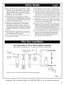
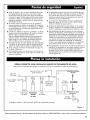
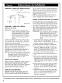
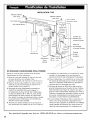
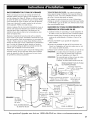
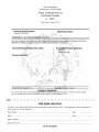
THE PROPER ORDER TO INSTALL WATER TREATMENT EQUIPMENT
(Shows sequence of equipment only - not all items are needed in all applications)
Cold Water
to House
Hot Water
to House
Untreated Water to
Outside Faucets
Water
Heater
Hybrid
Water
Softener
J
m
Iron
Filter
Sediment
Cartridge
Filter
• Always locate an Iron Filter UPSTREAM of the Hybrid Water Softener.
City Water Supply
Pressure
Tank
t
OR
I
Well Water Supply
Well
Pump
Figure 1
Questions? Call the Kenmore Water Line 1-800-426-9345 or visit www.kenmorewater.com
3

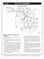
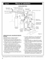
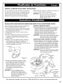
TYPICAL INSTALLATION
WHERE TO INSTALL THE HYBRID WATER
SOFTENER
Review the following points before you choose a place
to put your softener:
1. Place as close as possible to, but always downstream
from, the pressure tank (well water) or water meter
(city water).
2. Place as close as possible to a water drain such as a
floor drain, laundry tub, sump or standpipe (See Fig. 2).
3. Connect to the house main water pipe UPSTREAM
OF THE WATER HEATER (See Fig. 1). The tempera-
ture of water going through the softener must not be
more than IO0°F (38°C). Hot water will damage
inner softener parts. To reduce the risk of hot water
backup, piping between the softener and water
heater should be as long as possible.
4. Keep outside faucets on hard water to save soft
water and salt. See Fig. 2.
5. Do not install in a place where the softener could
freeze. Damage caused by freezing voids the war-
ranty by Sears Brands Management Corporation.
6. Put the softener in a place where water damage is
least likely to occur if it develops a leak. Sears or
the manufacturer will not repair or pay for water
damage.
7". A grounded, 120V, 60 Hz electrical outlet is needed
near the softener to plug in the power supply (See
Fig. 2). Be sure the outlet and power supply are in
an inside location, protected from wet weather. Use
a continuously "live" outlet, which cannot be acci-
dentally switched off.
8. When installing in an outside location, you must take
the steps necessary to assure the softener, installation
plumbing, and wiring, are protected from the ele-
ments, direct sunlight, contamination, vandalism, etc.
Questions? Call the Kenmore Water Line 1-800-426-9345 or visit www.kenmorewater.com
4

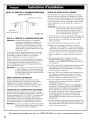
CHECK YOUR WATER PRESSURE BEFORE INSTALLING
For your water softener to work properly, incoming
water pressure in your house pipes must be no lower
than 20 pounds per square inch (psi). The highest
allowable pressure is 125 psi. If pressure is above 125
psi, buy and install a pressure reducing valve in the
pipe supplying water to the softener's inlet.
NOTE: If water pressure during the day is 100 psi or
more, pressure during the night may go above
125 psi.
INSTALL SINGLE BYPASS VALVE AND/OR THREADED INSTALLATION ADAPTORS
Complete the following steps to assemble the adaptors
and/or the included single bypass valve.
1. Close the shutoff valve on the house main water pipe,
near the water meter or pressure tank, to turn off the
water.
2. Shut off the gas or electric supply to the water
heater.
3. Open the highest and lowest water faucets in your
house. This will let water drain from the pipes.
Close faucets after water has drained.
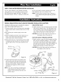
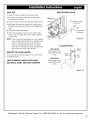
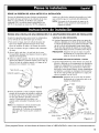
4. Remove the top cover. Pull outward on the two tabs
to release top cover (see Fig. 3). Set the cover and
salt lid aside so they will not get scratched or bro-
ken.
Salt Lid
Top
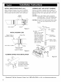
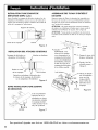
SINGLE BYPASS VALVE:
6. Lightly coat the o-rings with silicone grease and slide
them onto the bypass valve. Push the bypass valve
into the softener valve's inlet and outlet ports as far
as it will go. Snap the two large holding clips into
place, from the top down as shown (see Fig. 6).
CAUTION: Be sure the clips snap firmly into place so
the bypass valve will not pull out.
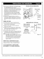
INLET AND OUTLET THREADED ADAPTORS:
7. Lightly coat the o-rings with silicone grease and slide
them onto the installation adaptors. Push the adap-
tors into the valve inlet and outlet ports, or bypass
valve ports, as far as they will go. Both adaptors are
the same and fit either port. Snap the two large
holding clips into place, as shown (see Fig. 6).
CAUTION: Be sure the clips snap firmly into place so
the adaptors will not pull out.
Figure 3
5. Visually check and remove any foreign mate-
rials from the valve inlet and outlet ports (see
Fig. 4). Carefully remove the two large plastic
clips (you will use them). Check to be sure
the turbine and support are firmly in place
(see Fig. 5).
NOTE: If you will not install the included bypass
valve because you will have a 3-valve
bypass in your plumbing, skip step 6, but
perform step 7.
Clips
Threaded
Valve Installation
Outlet Adaptors
O-Rings
Questions? Call the Kenmore Water Line 1-800-426-9345 or visit www.kenmorewater.com
5

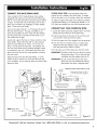
INSTALL SINGLE BYPASS VALVE (cont.)
Before installing the bypass valve and/or installation
adaptors, make sure that the turbine and support are
firmly in place inside the softener valve's outlet port.
Turbine
Support
Valve Outlet j Turbine /
Figure 5
INSTALL HOLDING CLIPS
Bypass Valve or
Installation Adaptor
\
Plastic Clip
ASSEMBLE INLET AND OUTLET PLUMBING
Measure, cut (thread if needed) and put together all
pipe and fittings up to the main water pipe. Make sure
that the incoming water supply pipe goes to the valve
inlet side.
CAUTION: Never solder fittings while connected to
nonmetallic parts. Wait until soldered pipe
has cooled before connection. See Fig. 8.
CAUTION: Be careful when putting pipe fittings togeth-
er. Do not cross thread, and do not over-
tighten.
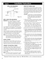
.
______ /Vlain Welter
Pipe
Incoming
Hard
Solder. _ Water
NOTE: To be certain
that heat will not
travel down the pipe
and into the bypass
valve or installation
adaptors, wrap the
bottom of the pipe
and the bypass valve
with a wet rag.
1. Cut pipe to
correct length
2. Solder. When
cool, do step 3.
Valve Inlet or Outlet
O-Ring
Plastic clip snaps
into groove in
bypass or adaptor
Figure 6
3. Put threaded
y adaptor into
IN bypass valve
port.
ALTERNATE BYPASS VALVE INSTALLATION
onnecting to floor
el plumbing, install
bypass valve turned
ownward, as shown
o,um
IN Figure 7
Clip
Figure 8
Questions? Call the I<enmore Water Line 1-800-426-9345 or visit www.kenmorewater.com
6

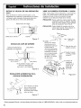
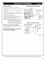
CONNECT THE VALVE DRAIN HOSE
Take a length of 3/8" inside diameter drain tubing
(supplied) and attach one end to the drain fitting (see
Fig. 9). Use a tube clamp from the parts bag to hold it
in place. Put the other end of the tubing over a floor
drain, into a laundry tub, standpipe, or other suitable
drain. Check your local codes.
Leave an air gap of about 1-1/2" between the end of
the hose and the drain. This gap is needed so you
don't get a backflow of sewer water into the softener.
Do not put the end of the hose into the drain or con-
nect without the air gap.
Locate and support the hose so it does not kink or have
sharp bends. Secure the hose end so water pressure
does not cause the hose to "whip". Tie or wire it in
place. Do not pinch the hose shut. The softener will
not work if this drain hose is pinched, plugged, closed
or restricted in any way. Direct drain flow down into
drain from drain line as flow could possibly overshoot
the drain cover.
Keep the hose lower than the drain fitting. In some
homes, to get to a drain you must raise the hose and
run it overhead. Do not raise the hose more than 8 feet
above the floor.
COPPER DRAIN TUBE: Local plumbing codes may
require the use a copper valve drain tube. A copper
tube is also best to use if running a drain line overhead.
To adapt a copper drain tube to the softener, purchase
a compression fitting (1/4" female pipe threads x 1/2"
O.D. tube) and tubing from your local hardware store.
CONNECT SALT TANK OVERFLOW HOSE
1. Locate the rubber grommet, adaptor elbow and tube
clamp (see Fig. 9) that are in the parts bag.
2. Push the grommet into the hole in the salt tank wall
so that half is inside and half is outside.
3. Push the larger end of the adaptor into the grommet.
4. Push one end of a length of 3/8" I.D. tubing (sup-
plied) onto the tube adaptor, using a tube clamp
from the parts bag to hold it in place.
5. Put the other end of the tubing over the floor drain.
IMPORTANT: Overflow water must run down by gravity
through the tubing. Do not raise the tub-
ing higher than the adaptor (see Fig. 9).
IMPORTANT: Do not connect this hose to the valve
drain hose you just installed (see above).
Both drains must have a separate hose.
NOTE: Drain Hose
_t Drain
ring
Tube ...._ I
Clamp
Grommet Tube
] d_ Adaptor
(12 ft.) is included.
\\
\\
xx
\\
\\
X\
X\
\\ Todrain
\\
\\ point other
\\
--_,_V'_lv_ _ than floor
drain.
Drain Hose
Support tub-
ing in place
Tie or wire 1-1/2" as needed.
tubing in Air Gap
place
Salt Tank
Overflow Hose FLOOR DRAIN
SUBSTITUTING RIGID DRAIN LINE
Clip 1/4 NPT
Threads CompressionFitting, 1/4 NPTx
Barbs 1/2" O.D. Tube(not supplied)
Cut barbs from drain fit- 1/2" Outside
ring {pull clip and remove Diameter Copper
fitting from valve) Tube (not supplied)
..... STANDPIPE
.... ='_ ____:L
Gap
. , Gap
_ LAUNDRY TUB
Figure 9
Questions? Call the Kenmore Water Line 1-800-426-9345 or visit www.kenmorewater.com
7

METAL PIPE GROUNDING
(parts not included)
Ground Wire
/
_[_F-igure 10
METAL WATER PIPE GROUNDING
IMPORTANT: This water softener has a non-metallic
valve system. Installing it on metal
plumbing will break electrical continuity,
which may interrupt grounding for the
home. You must restore electrical conti-
nuity in your metal plumbing system.
If you installed a 3-valve bypass system (Fig. 12), elec-
trical continuity will be maintained. If you installed the
non-metallic bypass valve (Fig. 11), restore the ground
as follows:
Install a #4 copper wire (parts not included) across the
removed section of metal water pipe, securely clamping
it at both ends (See Fig. 10). Be sure the pipes are
clean under the clamps, to assure good contact.
NOTE: If you are installing a sediment filter or other
item(s) into the plumbing system, along with the
water softener, be sure to restore electrical con-
tinuity across all removed metal pipe sections.
INSTALL COVERS
After installing your water softener, put the covers on.
Angle the covers so the top cover clips onto the back
first, then bring down in front and clip on the tabs
inside the rim and lower the salt lid closed (See Fig. 3).
CONNECT TO ELECTRICAL POWER
The softener works on 28V DC electrical power. The
included power supply converts 120V AC household
power to 28V DC. Plug the water softener's power sup-
ply into a grounded, 120V, 60 Hz electrical outlet. Be
sure the outlet is always "live" so it cannot be switched
off by mistake.
NOTE: The electrical outlet you plug the power supply
into must be indoors, protected from weather.
RINSE OUT CARBON FINES
Small particles of carbon filtration material are gener-
ated during manufacturing and shipping, which will exit
the media tank with the first water flow. These carbon
"fines" are not harmful, but give the water a gray color
and should be rinsed down the drain before any water
from the softener is directed to the home's faucets or
water heater.
CAUTION: To avoid water or air pressure damage to
softener inner parts, and to flush pipe chips
or other residue from the water pipes, be
sure to do the following steps exactly as
instructed.
1. Make sure the softener's valve drain hose is hooked
up and the open end directed to a floor drain, laun-
dry tub or other suitable type of drain.
2. The system should be connected to electrical power.
3. Place bypass valve(s) in "bypass" position (see
Figures 11& 12). On a single valve, slide the stem
inward to bypass. On a 3-valve bypass, close the
inlet and outlet valves and open the bypass valve.
4. Fully open the house main water pipe shutoff valve.
5. Initiate a regeneration by pressing and holding for 3
seconds the REGENERATION button (see instruction
decal under the salt lid). The valve motor will start
running and the valve will advance to the "Fill" posi-
tion.
6. After you hear the valve motor stop running (valve in
"Fill" position), press, but do not hold, the REGENER-
ATION button. The valve will advance to the "Brine"
position.
7. After you hear the valve motor stop running (valve in
"Brine" position), press, but do not hold, the REGEN-
ERATION button. The valve will advance to the
"Backwash" position.
8. Once the unit is in backwash, place bypass valve(s)
in SERVICE, EXACTLY as follows:
a. Single Bypass Valve: Slowly, slide pull the valve
stem outward toward service, pausing several times
to allow the softener to pressurize gradually.
b. 3-Valve Bypass: Fully close the bypass valve and
open the outlet valve. Slowl_z open the inlet valve,
pausing several times to allow the softener to pres-
surize gradually.
9. Let the softener complete the backwash and fast
rinse cycles (takes about 20 minutes). When the
regeneration ends, the softener's valve returns to the
service position.
Questions? Call the I<enmore Water Line 1-800-426-9345 or visit www.kenmorewater.com

LEAK TEST
To check for leaks, complete the following steps:
1. Fully open two nearby cold water faucets down-
stream from the softener.
2. Observe steady weater flow from both open faucets.
3 After about three minutes, open a hot water faucet
for about one minute, or until all air is expelled, then
close.
4. Close both cold water faucets.
5. Check your plumbing work for leaks, and fix right
away if any are found. Be sure to observe previous
caution notes.
NOTE: If this procedure is performed on a new softener,
water coming from the taps may initially be dis-
colored. This normally occurs the first time
water runs through the resin bed. The discol-
ored water is not harmful, and the discoloration
will not last more than a few minutes.
RESTART THE WATER HEATER
Turn on the gas (or electric) supply to the water heater
and light the pilot.
YOUR PLUMBING INSTALLATION AND
ELECTRICAL WORK ARE NOW COMPLETE.
SINGLE BYPASS VALVE
Pull stem outward
for Service
Push inward
for Bypass
Figure 11
3-VALVE BYPASS
FOR SERVICE
Close bypass valve.
Open inlet & outlet
valves.
Outlet
Valve
FOR BYPASS
Open bypass valve.
Close inlet & outlet
valves.
Bypass
Valve
Inlet
Valve
Figure 12
Questions? Call the I<enmore Water Line 1-800-426-9345 or visit www.kenmorewater.com
9

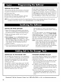
PROGRAMTHESOFTENER
Lift the salt lid and follow the instructions on the decal
to program the following into the electronic controller:
• Current time of day
• Hardness of your water supply
• Time of day when automatic recharges will begin
• Type of salt you will be using (NaCI or KCI)
In the state of California: You must turn the Salt
Efficiency Feature setting to ON. This may initiate
more frequent recharges. However, it will operate at
4,000 grains per pound of salt or higher. To turn on
the Salt Efficiency Feature, follow the instructions in
the "Salt Efficiency" section of the owner's manual.
NOTE: You can find complete instructions for programming the softener and customizing features of the electronic
controller in the owner's manual. Go to www.sears.com or call 1-800-426-9345.
SANITIZE THE WATER SOFTENER
1. Open salt lid, remove the brinewell cover and pour
about 3 oz. (6 tablespoons) of household bleach into
the softener brinewell. Replace the brinewell cover.
2. Make sure the bypass valve(s) is in the "service"
(open) position.
3. Start a recharge: Press the REGENERATION button
and hold for 3 seconds, until "RECHARGE", "Serv"
and "Fill" begin to flash in the display. This recharge
draws the sanitizing bleach into and through the
water softener. Any air remaining in the unit is
purged to the drain.
4. After the recharge has completed, fully open a cold
water faucet, downstream from the softener, and
allow 50 gallons of water to pass through the sys-
tem. This should take at least 20 minutes. Close the
faucet.
Your new Sears softener is now softening the water for
your household needs. However, your WATER HEATER
is filled with hard water. To have fully soft water right
away, you can drain the water heater so it refills with
soft water. If you don't drain the water heater, it will
take a few days before you have fully soft water.
NOTE: If this procedure is performed on a new softener,
water coming from the taps may initially be dis-
colored. This normally occurs the first time
water runs through the resin bed. The discol-
ored water is not harmful, and the discoloration
will not last more than a few minutes.
ADDING SALT TO THE STORAGE TANK
You must keep salt in the tank, but it is not necessary to
fill it full. Especially in humid areas, it is best to fill the
storage tank no more than half full, and to add salt
more often. Salt "bridging" occurs more often when
conditions are humid.
Use NUGGET or PELLET water softener salt. DO NOT
use rock salts, as they have dirt and sediments that will
stop the softener from working. To maintain optimum
performance of your water softener, the salt tank
should be cleaned out every 2 to 3 years.
POTASSIUM CHLORIDE (I(CI) SALT
If you choose Potassium Chloride (KCI) as a regenerant,
following these suggestions will help give you years of
maintenance free service.
1. Place only one bag of I<CI in your softener at a time
(the salt storage tank should contain no more than
60 pounds of I<CI at any one time).
2. A softener using I<CI should not be placed in areas
with temperature fluctuations and high humidity (KCI
will harden in these environments and may make the
softener inoperable).
3. Be sure to set "Salt Type" on the controller to "I<CI".
This setting adjusts the regeneration cycle times to
compensate for the different rate at which I<CI dis-
solves.
Questions? Call the Kenmore Water Line 1-800-426-9345 or visit www.kenmorewater.com
10

Installation Instructions
Instrucciones de Instalaci6n
Instructions d'installation
English / Espaffol / Fran_:ais
Models / Moclelos / ModUles
625.385200
625.75590
For a detailed Use and Care Guide, including
specifications, programming and parts list, go to:
www.sears.com (U.S.A.) www.sears.ca (Canada)
or call the Kenmore Water Line at
1-800-426-9345
Para obtener el manual detellado de us@y
cuidado, con especificaciones, programaci6n
y lista de piezas, visite el sitio:
www.sears.com (Estados Unidos) www.sears.ca (Canad6)
o Ilame a la linea directa de Kenmore Water al
1-800-426-9345
Pour obtenir un guide d6taill6 d'utilisation
et d'entretien, y compris les sp6cifications,
la programmation, et la liste des pi_ces, visitez :
www.sears.com (l_tats-Unis) www.sears.ca (Canada)
ou appelez la ligne d'assistance de Kenmore au
1-800-426-9345
I(enrnore Elite
@
A w_"lllll'e_sof"lllll'ene_ _nd _ whe_e home fiPlllll'e_in one
° Agu
Un ab_andador de agua con fHff@ in_egrad@ para toda _a casa
@ @
A _® lois ®deu¢[sseur d_e_u et sysf6_e de filtration centr®_
Sears Brands Management Corporation
3333 Beverly Road
Hoffman Estates, IL 60179 U.S.A
www.kenmorewater.com
www.kenmore.com
www.sears.com
Sears Canada Inc.
290 Yonge Street
Toronto, Ontario M5B 2C3 Canada
www.sears.ca

GARANTJA PARA EL ABLANDADOR HJBRIDO DE AGUA KENMORE ELITE®
GARANTJA LIMITADA DE UN AI_IO PARA EL ABLANDADOR HJBRIDO DE AGUA
Cuando se haya instalado, operado y mantenido conforme a todas las instrucciones suministradas con el pro-
ducto, si este artefacto Kenmore fallara debido a defectos en materiales o mano de obra dentro de un afio a
partir de la fecha de compra, Ilame al 1-800-4-MY-HOME ® para solicitar la reparaci6n gratuita.
GARANTJA LIMITADA DE TRES AI_IOS PARA LAS PIEZAS ELECTRONICAS
Cuando se haya instalado, operado y mantenido el producto conforme a todas las instrucciones suministradas
con el mismo, si fallara cualquiera de las siguientes piezas electr6nicas debido a defectos en materiales o
mano de obra, Ilame al 1-800-4-MY-HOME ® para solicitar el reemplazo gratuito de la pieza: luz del tanque
de salmuera, tablero electr6nico, caja del sensor, mazo de cables, transformador, microinterruptor, motor
impulsor, cable el6ctrico. Despu6s del primer afio, usted deber6 pagar un cargo inicial por viaje.
GARANTJA LIMITADA DE DIEZ AI_IOS CONTRA FUGAS
Cuando se haya instalado, operado y mantenido conforme a todas las instrucciones suministradas con el pro-
ducto, si el tanque o el tambor de almacenamiento de sal del ablandador de agua tuviera una fuga dentro
de los diez a_os de la fecha de compra, Ilame al 1-800-4-MY-HOME ® para solicitar el reemplazo gratuito del
tanque o del tambor. Despu_s del primer a_o, usted deber6 pagar un cargo inicial por viaje.
La cobertura de la garantia total no incluye la resina del ablandador de agua o el carb6n, los cuales son
articulos consumibles.
Si este artefacto Ilegara a usarse alguna vez con un prop6sito ajeno al de una familia privada, esta garantia
se aplicar6 por s61o 90 dias a partir de la fecha de compra.
La presente garantia s61o cubre defectos en materiales y mano de obra. Sears NO pagard:
1. A un t6cnico de servicio para instruir al usuario sobre la forma correcta de instalar, operar o mantener
el producto.
2. A un t6cnico de servicio para limpiar o dar mantenimiento a este producto.
3. El da_o o la falla de este producto si no se instala, opera ni mantiene conforme a todas las instrucciones
suministradas con el producto.
4. El da_o o la falla de este producto originado por accidentes, maltratos, uso incorrecto o uso ajeno al
prop6sito de disefio.
5. El da_o o la falla de este producto causado por el uso de detergentes, productos de limpieza, productos
quimicos o utensilios que no sean los recomendados en todas las instrucciones suministradas con el producto.
6. El da_o o la falla de piezas o sistemas originado por modificaciones no autorizadas hechas a este producto.
Exenci6n de responsabilidad por garantias implicitas; limitaci6n de recursos
Conforme a la presente garantia limitada, el recurso Onico y exclusivo para el cliente ser6 la reparaci6n del
producto seg0n Io aqui estipulado. Las garantias implicitas, incluyendo las garantias de comerciabilidad o
aptitud para un prop6sito en particular, se limitan a un a_o o al periodo m6s breve que permite la ley. Sears
no se responsabilizar6 de da_os imprevistos o emergentes. En ciertas jurisdicciones no se permite la exclusi6n
o limitaci6n de dafios imprevistos o emergentes, o no se permite la limitaci6n de la duraci6n de las garantias
implicitas de comerciabilidad o aptitud, de modo que las presentes exclusiones o limitaciones podrian no apli-
carse a usted.
Esta garantia se aplicar6 solamente mientras este artefacto se use en los Estados Unidos o Canad6.
Esta garantia le otorga derechos legales especificos, yes posible que usted tambi6n tenga otros derechos,
los cuales varian de una jurisdicci6n a otra.
Sears Brands Management Corporation, Hoffman Estates, IL 60179 U.S.A.
Sears Canada Inc., 290 Yonge Street, Toronto, Ontario MSB 2C3 Canada
_Tiene preguntas? Llame a la Ifnea directa de Kenmore Water al 1-800-426-9345 o visite el sitio www.kenmorewater.com
12

• Antes de instalar y usar el nuevo ablandador de agua,
lea atentamente todos los pasos y las pautas. Siga
exactamente todos los pasos para Iograr la instalaci6n
correcta. No seguir dichos pasos podrfa causar lesiones
corporales o dafios a la propiedad. Leer este manual
tambi6n Io ayudar6 a obtener todos los beneficios del
ablandador de agua.
• No intente utilizar este producto a fin de potabilizar
agua proveniente de fuentes no potables. Si el agua es
microbiol6gicamente impura o si se desconoce su calidad,
no use el sistema sin una adecuada desinfecci6n antes o
despu6s del sistema.
• Consulte los c6digos de plomerfa y sanidad a su depar-
tamento local de obras pOblicas. AI instalar el sistema
deber6 seguir las pautas que le indiquen.
Siga sus c6digos locales si difieren con las pautas del
presente manual. En el Estado de Massachusetts, se
debe cumplir con los c6digos de plomerfa 248-CMR
3.00 y 10.00. Consulte a un plomero con licencia.
• AI instalar tuberfas de cobre soldado, use s61o soldadura
y fundente sin plomo para todas las conexiones de sol-
dadura con estafio, seg0n Io exigen los c6digos federales.
• Tenga cuidado al manejar el ablandador de agua. No
Io voltee ni deje caer.
• Evite instalarlo bajo la luz directa del sol. El exceso de
calor puede distorsionar o causar algOn otro da_o alas
piezas no met61icas.
• El ablandador de agua funciona con presiones de agua
de 20 PSI a 125 PSI (en Canad6, la m6xima es 100 PSI).
Si la presi6n del agua de su casa supera la m6xima,
instale una v61vula reductora de presi6n en la Ifnea de
suministro de agua al ablandador.
• La temperatura del suministro de agua al ablandador
debe estar entre 40 °F y 100 °F (4 °C y 38 °C). No Io
instale en tuberfas de agua caliente.
• Si instala el ablandador de agua afuera, no Io coloque
donde se exponga a la humedad clim6tica, la luz solar
directa o temperaturas extremadamente calientes o frfas.
• Este ablandador de agua funciona con una corriente
continua de 28 voltios, suministrada por una fuente de
alimentaci6n el6ctrica directa enchufable (que se incluye).
AsegOrese de usar la fuente de alimentaci6n el6ctrica
incluida y de enchufarlo a un tomacorriente dom6stico
con r6gimen nominal de 120 voltios, 60 hercios, que se
encuentre en un lugar seco solamente, es conectado
a tierra y est6 debidamente protegido por un dispositivo
para sobrecorriente, como un disyuntor o un fusible.
• Este ablandador de agua tiene un sistema de v61vulas no
met61icas. Su instalaci6n en una tuberfa met61ica cortar6
la continuidad el6ctrica, Io cual puede interrumpir la
conexi6n a tierra de la vivienda. Debe restaurar la con-
tinuidad el6ctrica en el sistema de la tuberfa met61ica
(vea la p6gina 18).
ORDEN CORRECTO PARA INSTALAR EL EQUIPO DE TRATAMIENTO DE AGUA
($61o ilustra la secuencia del equipo. No todos los articulos se necesitan en todas las aplicaciones.)
Agua fria
a la casa
Agua caliente
a la casa
Agua sin tratar a los
grifos externos
Cartucho fil-
trante para
sedimentos
Calentador Ablandador Filtro
de agua hibrido de hierro
de agua
Suministro municipal
de agua
t
• Siempre coloque un filtro de hierro ANTES del ablandador de agua.
Tanque
de presi6n 0 BIEN
I Suministro de agua
de cisterna
Bomba
de cisterna
t
Figura 1
_Tiene preguntas? Llame a la Ifnea directa de Kenmore Water al 1-800-426-9345 o visite el sitio www.kenmorewater.com
13

INSTALACION TiPICA
Grifo exterior
(agua dura)
Agua blanda fria
El alambre de conexi6n a tierra
debe hacer contacto con los
tubos
Grifo exterior
(agua dura)
AI grifo de 6smosis inversa
Agua blanda caliente
120V,
60 Hz
Calentador
de agua
V_lvula
de paso
Ablandador
hibrido
de agua
DONDE INSTALAR EL ABLANDADOR HIBRIDO
DE AGUA
Antes de seleccionar un lucjar para instalar el
ablandador, examine los siguientes puntos:
1. Col6quelo tan cerca como sea posible del tanque
de presi6n (agua de cisterna) o del medidor de agua
(agua municipal), pero siempre despu_s de este.
2. Col6quelo tan cerca como sea posible de un desagLie
tal como uno de piso, una pileta de lavadero, un
sumidero o un tubo vertical (vea la Fig. 2).
3. Conecte la tuberia principal de agua de la casa
ANTES DEL CALENTADOR DE AGUA (vea la Fig. 1).
La temperatura del agua que ingresa al ablandador
no debe superar los 100 °F (38 °C). El agua caliente
da_ar6 las piezas internas del ablandador. Para
reducir el riesgo de reflujo de agua caliente, la
tuberia entre el ablandador y el calentador
de acjua debe ser tan larcja como sea posible.
4. Mantenga los grifos exteriores conectados al sumin-
istro de agua dura para economizar agua blanda y
sal. Vea la Fig. 2.
Agua blanda
al sistema de
6smosis inversa
Medidor
de agua
DesagLie Separaci6
de aire de
de piso 1-1/2pulg.
Sistema de
6smosis inversa
Tanque de alma-
cenamiento de
6smosis inversa
V61vula
de paso
principal
Figura 2
5. No instale el ablandador en un lugar donde pueda
congelarse. El da_o causado por congelamiento
anula la garantia de Sears Brands Manacjement
Corporation.
6. Instale el ablandador en un lugar donde sea menos
probable que el agua cause da_os en caso de fuga.
Ni Sears ni el fabricante reparar6 ni pagar6 el da_o
causado por el agua.
7. Para enchufar la fuente de alimentaci6n el6ctrica, se
necesita un tomacorriente con r6gimen de 120 voltios,
60 hercios y conexi6n a tierra, cerca del ablandador
(vea la Fig. 2). Cerci6rese de que el tomacorriente y
la fuente de alimentaci6n el6ctrica est6n ubicados en
el interior y protegidos de la humedad clim6tica. Util-
ice un tomacorriente con alimentaci6n permanente,
que no pueda interrumpirse accidentalmente.
8. AI instalar el equipo en una ubicaci6n exterior, deber6
tomar las medidas necesarias para garantizar que el
ablandador, la plomeria de la instalaci6n y el cableado
est6n protegidos contra los factores clim6ticos, la luz
solar directa, la contaminaci6n, el vandalismo, etc.
_Tiene preguntas? Llame a la Ifnea directa de Kenmore Water al 1-800-426-9345 o visite el sitio www.kenmorewater.com
14

REVISE LA PRESION DEL AGUA ANTES DE LA INSTALACION
Para que el ablandador de agua funcione correctamente,
la presi6n del agua entrante en las tuberias de la casa
debe ser, como minimo, de 20 libras por pulgada
cuadrada (PSI). La maxima presi6n permisible es de
125 PSI. Si la presi6n es mayor de 125 PSI, adquiera e
instale una v_lvula de reducci6n de presi6n en el tubo
que suministra agua a la entrada del ablandador.
NOTA: Si durante el dia la presi6n de agua es de
100 PSI o m6s, durante la noche puede ser
superior a 125 PSI.
INSTALE UNA VALVULA DE UNA DERIVACION Y/O ADAPTADORES ROSCADOS DE INSTALACION
Cumpla los siguientes pasos para armar los adaptadores
y/o la v_lvula de una derivaci6n que se incluye.
1. Para cerrar el agua, cierre la v61vula de paso del
agua en la tuberia principal de agua de la casa,
cerca del medidor de agua o el tanque de presi6n.
2. Corte el suministro de gas o el6ctrico del calentador
de agua.
3. Abra el grifo m6s alto y el m6s bajo de la casa.
Eso permitir_ desaguar las tuberias. Cierre los grifos
despu_s de desaguarlas.
4. Retire la cubierta superior. Tire de las dos aletas hacia
afuera para liberar la cubierta superior (vea la Fig. 3).
Deje a un lado la cubierta superior y la tapa de sal
para que no se rompan ni se rayen.
Tapa de sal
Cubierta su
Figura 3
5. Revise visualmente y retire cualquier material
extrafio de los puertos de entrada y salida de
la v61vula (vea la Fig. 4). Retire con cuidado
los dos clips pl6sticos grandes (volver6 a
usarlos). Compruebe que la turbina y el
soporte est6n colocados firmemente (vea la
Fig. 5).
NOTA: Si no instalar6 la v61vula de derivaci6n
que se incluye porque habr6 una
derivaci6n de 3 v61vulas en la plomeria,
pase por alto el paso 6, pero cumpla el
paso 7.
VALVULA DE UNA DERIVACION:
6. Lubrique ligeramente las juntas t6ricas con grasa de
silicona y deslicelas en la v61vula de derivaci6n. Empuje
la v61vula de derivaci6n en los puertos de entrada y sali-
da de la v61vula del ablandador hasta dande Ilegue.
Fije los dos clips grandes de soporte en su lugar, desde
arriba hacia abajo, tal como se muestra (vea la Fig. 6).
PRECAUCION: AsegOrese de que los clips se ajusten
firmemente en su lugar para que no se
salga la v61vula de derivaci6n.
ADAPTADORES ROSCADOS DE ENTRADA Y SALIDA:
7. Lubrique ligeramente las juntas t6ricas con grasa de
silicona y deslicelas en los adaptadores de instalaci6n.
Empuje los adaptadores en los puertos de entrada y
salida de la v61vula o los puertos de la v61vula de
derivaci6n, hasta donde Ileguen. Ambos adaptadores
son id_nticos y encajan en cualquiera de los puertos.
Fije los dos clips grandes de soporte en su lugar, tal
como se muestra (vea la Fig. 6).
PRECAUClON: AsegOrese de q ue los clips se ajusten
firmemente en su lugar para que no se
salgan los adaptadores.
Clips
Salida Adaptadores
de la roscados de
v_lvula instalaci6n
_Tiene preguntas? Llame a la Ifnea directa de Kenmore Water al 1-800-426-9345 o visite el sitio www.kenmorewater.com
15

INSTALE LA VALVULA DE UNA DERIVACION
(cont.)
Antes de instalar la v61vula de derivaci6n y/o los
adaptadores de instalaci6n, compruebe que la turbina
y el soporte est6n colocados firmemente dentro del
puerto de salida de la v61vula del ablandador.
Soporte para la turbina
Salida de la v61vula j Turbina /
Figura 5
INSTALE LOS CLIPS DE SOPORTE
V61vula de derivaci6n o
adaptador de instalaci6n
\
Clip pl6stico
Entrada o salida
de la v61vula
lunta t6rica
El clip pl6stico encaja a pre-
si6n en la ranura de la
derivaci6n o del adaptador
Figura 6
INSTALACION ALTERNATIVA DE LA
VALVULA DE DERIVACION
ARME LA PLOMERIA DE ENTRADA Y SALIDA
Mida, corte (rosque si fuera necesario) y arme todos los
tubos y las uniones hasta el tubo de agua principal.
AsegOrese de que el tubo de suministro de agua
entrante vaya al lado de entrada de la v61vula.
PRECAUCION: Nunca suelde las uniones mientras est6n
conectadas a piezas no met61icas. Aguarde
hasta que el tubo soldado se haya enfriado
antes de conectarlo. Vea la Fig. 8.
PRECAUCION: Tenga cuidado al conectar entre si las
uniones para tuberia. Evite estropear la
rosca y apretarla demasiado.
,
TUberFaPrincipa I
Agua dura
entrante
7
Suelde.
NOTA: Para asegu-
rarse de que no se
transmita el calor por
el tubo hacia la
v61vula de derivaci6n
o los adaptadores de
instalaci6n, envuelva
con un trapo hOmedo
el extremo inferior
del tubo y la v61vula
de derivaci6n.
Junta t6rica
1. Corte el tubo a la
medida correcta.
2. Suelde. Cuando
se enfrie, cumpla
el paso 3.
ENT.
Clip
3. Coloque el
adaptador
roscado en el
puerto de la
v61vula de
derivaci6n.
Figura 8
ENT.
SAL.
Si la conecta a la plom-
eria a nivel del piso,
instale la v61vula de
derivaci6n hacia aba]o,
como se ilustra.
Figura 7
_Tiene preguntas? Llame a la Ifnea directa de Kenmore Water al 1-800-426-9345 o visite el sitio www.kenmorewater.com
16

CONECTE LA MANGUERA DE DESAGOE
PARA LA VALVULA
Tome una secci6n de tuberia de desagiJe de 3/8 pulg.
de di6metro interior (suministrada) y conecte un extremo
a la uni6n de desagLie (yea la Fig. 9). Mant6ngalo en su
sitio con una abrazadera para tubo provista en la bolsa
de piezos. Coloque el otro extremo del tubo sobre un
desagLie de piso, una pileta de lavadero, un tubo vertical
u otro desagLie adecuado. Consulte los c6digos locales.
Deje una separaci6n de aire de aproximadamente
1-1/2 pulg. (3.8 cm) entre el extremo de la manguera y
el desagLie. Se necesita esa separaci6n pora evitar el
reflujo de agua residual al ablandador. No coloque el
extremo de la manguera de desagLie dentro del
desagLie ni la conecte sin la separaci6n de aire.
Ubique y sostenga la manguera de modo que quede sin
dobleces ni vueltas cerradas. Fije el extremo de la
manguera para que la presi6n de agua no la sacuda.
Fijela en su sitio con alambre o amarres. No cierre la
manguera oprimi6ndola. El ablandador no funcionar6
siesta manguera de desagLie est6 oprimida, obstruida,
cerrada o torcida de alg0n modo. Dirija el flujo del
desagLie hacia abajo desde la linea del desagLie, ya
que podria sobrepasar la tapa del desagLie.
Mantenga la manguera pot debajo de la uni6n del
desagLie. En ciertas viviendas, para acceder a un
desagLie hay que levantar la manguera y tenderla en
una posici6n elevada. Evite levantar la manguera m6s
de 8 pies (2.4 m) por arriba del nivel del piso.
TUBO DE DESAGUE DE COBRE: Esposible que los c6digos
locales de plomeria exijan usar un tubo de desagLie con
v61vula de cobre. Asimismo, si se tiende un desagLie
elevado, Io m6s conveniente es un tubo de cobre.
para tubo
dReUteddaa Adaptador
de tubo
NOTA: Se incluye la
manguera det
desagiJe (12 pies /
3.6 m).
Manguera de sobreftujo m
del tanque de sat
A fin de adaptar un tubo de desagiJe de cobre al
ablandador, compre una uni6n de compresi6n (1/4 pulg.
de rosca hembra x 1/2 pulg. de D.E. de tubo) y la
tuberia correspondiente en su ferreteria local.
CONECTE LA MANGUERA DE SOBREFLUJO
DEL TANQUE DE ALMACENAMIENTO DE SAL
1. Ubique la rueda dentada de caucho, el codo adap-
tador y la abrazadera para tubo (yea la Fig. 9) que
est6n en la bolsa de piezas.
2. Inserte la rueda dentada pot el orificio de la pared
del tanque de almacenamiento de sal, de modo que
quede una mitad adentro y la otra afuera.
3. Empuje el extremo m6s grande del adaptador den-
tro de la rueda dentada.
4. Empuje un extremo de una secci6n de tubo de
3/8 pulg. de D.I. (suministrado) en el adaptador de
tubo, manteni6ndolo en su sitio con una abrazadera
para tubo de la bolsa de piezas.
5. Coloque el otro extremo del tubo sobre el desagLie
del piso.
IMPORTANTE: El sobreflujo de agua tiene que correr
hacia abajo por la tuberia debido a la
gravedad. No eleve el tubo m6s que el
adaptador (vea la Fig. 9).
IMPORTANTE: No conecte dicha manguera a la
manguera de desagLie de la v61vula que
instal6 reci6n (vea las instrucciones
anteriores). Cada desagLie debe tener su
propia manguera.
SUBSTITUCION CON TUBERiA RiGIDA DE DESAGOE
\\
\\
xx
\\
\\
\\
\\
\\
\\ A un punto
Manguera \\ dedesag(Je
\\
de desagLie _ que nosea
para la v61vula _'_ undesag_Je
de piso. Fije
el tubo en su
sitio segOn se
Fije el tubo Separaci6n necesite.
en su sitio de aire de
con alambre 1-1/2 pulg.
o amarres.
DESAGUE
DE PISO
Clip Roscas NPT
de /4 pulg.
Uni6n de compresi6n NPT de 1/4 x tubo
Rebabas de 1/2 pulg. de D.E. (no se incluye)
Corte las rebabas de la uni6n
para desag_e (tire del clip y
separe la uni6n de la v61vula)
Tubo de cobre de
1/2 pulg. de D.E.
(no se incluye)
_ TUBO VERTICAL
--T
_ Separacidn
II de aire de
j_/2 pulg.
Separaci6n de
_.aire de 1-1/2 pulg.
._._ PILETA DE LAVADERO
Figura 9
_Tiene preguntas? Llame a la linea directa de Kenmore Water al 1-800-426-9345 o visite el sitio www.kenmorewater.com
17

CONEXIONA TIERRAPORTUBERJAMETALICA
(no se incluyen las piezas)
Abraz_
(2) i I
Alambre de conexi6n a tierra
/
_Figura 10
CONEXION A TIERRA POR TUBERiA
METALICA DE AGUA
IMPORTANTE: Este ablandador de agua tiene un sis-
tema de v61vulas no met61icas. Su insta-
laci6n en una tuberia met61ica cortar6
la continuidad el6ctrica, Io cual puede
interrumpir la conexi6n a tierra de la
vivienda. Debe restaurar la continuidad
el6ctrica en el sistema de la tuberia
met61ica.
Si instal6 un sistema de derivaci6n de 3 v61vulas (Fig.
12), se mantendr6 la continuidad el6ctrica. Si instal6 la
v61vula de derivaci6n no met61ica (Fig. 11), restaure la
conexi6n a tierra de esta manera:
Instale un alambre de cobre calibre 4 (no se incluye la
pieza) a trav6s de la secci6n de la tuberia met61ica de
agua que se retir6, fij6ndolo firmemente con
abrazaderas a ambos extremos (vea la Fig. 10).
Compruebe que los tubas est6n limpios debajo de las
abrazaderas para que haya un buen contacto.
NOTA: Si instala un filtro de sedimentos u otros elemen-
tos en el sistema de plomeria, ]untamente con el
ablandador de agua0 no olvide restaurar la
continuidad el6ctrica a trav_s de todas las sec-
clones de tuberia met61ica que retire.
INSTALE LAS CUBIERTAS
Despu_s de instalar el ablandador de agua, coloque las
cubiertas. Coloque las cubiertas en 6ngulo de modo
que la superior se enganche primero en su parte
trasera; luego haga bajar la parte delantera, eng6nchela
con las aletas que hay dentro del reborde y baje la
tapa de la sal para cerrarla (vea la Fig. 3).
CONECTE LA ELECTRICIDAD
ablandador funciona con una corriente continua de
28 voltios. La fuente de alimentaci6n el6ctrica que se
incluye convierte la corriente de 120V CA dom6stica a
28V CC. Enchufe la fuente de alimentaci6n el6ctrica del
ablandador de agua a un tomacorriente de 120 voltios,
60 Hz, con puesta a tierra. Cerci6rese de que el toma-
corriente tenga alimentaci6n permanente para que no
pueda interrumpirse par error.
NOTA: El tomacorriente el6ctrico donde enchufe la
fuente de alimentaci6n el6ctrica tiene que estar en el
interior y protegido de los factores clim6ticos.
PURGUE LAS PARTICULAS FINAS DE CARBONO
Durante la fabricaci6n y el envio del producto se gen-
eran pequeBas particulas de material filtrante de car-
bona, las cuales saldr6n del tanque de medias filtrantes
con el primer flujo de agua. Dichas "particulas finas"
de carbono no son daBinas pero le dan un color gris al
agua y deben purgarse par el desag_ie antes de que se
dirija cualquier porci6n de agua del ablandador a los
grifos o el calentador de agua de la casa.
PRECAUCION: A fin de prevenir el da_o de las piezas
internas del ablandador causado par la
presi6n del agua o del aire, y para
eliminar los restos de tuba u otros resid-
uos de las tuberias de agua, no deje de
cumplir los siguientes pasos tal cual se
indica.
1. Compruebe que est6 conectada la manguera de
desagiJe de la v61vula del ablandador y el otro
extremo se dirija a un desagi.ie de piso, una pileta de
lavadora u otro tipo adecuado de desagiJe.
El sistema debe estar conectado a la electricidad..
3.
.
5.
.
7.
Mueva las v61vulas de derivaci6n a la posici6n de
"derivaci6n" (Bypass) (vea las Fig. 11y 12). En una
v61vula de una derivaci6n, deslice el v6stago hacia
adentro a la posici6n de derivaci6n. En una
derivaci6n de 3 v61vulas, cierre las v61vulas de entra-
day salida, y abra la v61vula de derivaci6n.
Abra totalmente la v61vula de paso de agua de la
casa.
Inicie un ciclo de regeneraci6n; para ella mantenga
oprimido par 3 segundos el bot6n REGENERATION
(regeneraci6n) (vea la calcomania con instrucciones
debajo de la tapa de la sal). Comenzar6 a funcionar
el motor de la v61vula y esta avanzar6 a la posici6n
"Fill" (llenado).
Cuando haya oido que el motor de la v61vula deja
de funcionar (la v61vula est6 en la posici6n "Fill"),
oprima una vez el bot6n REGENERATION (regen-
eraci6n). La v61vula avanzar6 a la posici6n "Brine"
(salmuera).
Cuando haya oido que el motor de la v61vula deja
de funcionar (la v61vula est6 en la posici6n "Brine"),
oprima una vez el bot6n REGENERATION (regen-
eraci6n). La v61vula avanzar6 a la posici6n
"Backwash" (retrolavado).
_Tiene preguntas? Llame a la linea directa de Kenmore Water al 1-800-426-9345 o visite el sitio www.kenmorewater.com
18

8. Una vez que la unidad est@ en retrolavado, mueva
la(s) v61vula(s) de derivaci6n a la posici6n de SERVI-
CIO, EXACTAMENTE de esta manera:
a. V61vula de una derivaci6n: Deslice lentamente el
v6stago de la v61vula hacia afuera hasta la posici6n
de servicio, con varias pausas para permitir que el
ablandador se presurice gradualmente.
b. Derivaci6n de 3 v61vulas: Cierre totalmente la
v61vula de derivaci6n y abra la v61vula de salida.
Abra lentamente la v61vula de entrada, con varias
pausas para permitir que el ablandador se presurice
gradualmente.
9. Deje que el ablandador finalice los ciclos de
retrolavado y enjuague r6pido (lleva unos 20 minu-
tos). Cuando finalice la regeneraci6n, la v61vula del
ablandador regresar6 a la posici6n "Service" (servi-
cio).
PRUEBA DE FUGAS
Para detectar fugas, cumpla los siguientes pasos:
1. Abra totalmente dos grifos de agua fria cercanos,
situados despu_s del ablandador.
2. Observe si hay un flujo constante de agua per
ambos grifos abiertos.
3. Despu_s de unos tres minutos, abra un grifo de agua
caliente durante aproximadamente un minute, o hasta
que se purgue todo el aire, luego ci6rrelo.
4. Cierre ambos grifos de agua fria.
5. Compruebe si hay fugas en su trabajo de plomeria y,
si encuentra alguna, rep6rela de inmediato. No olvide
tener presente las notas anteriores de precauci6n.
NOTA: Si se realiza el procedimiento con un
ablandador nuevo, es posible que al principio el
agua salga descolorida de los grifos. Eso ocurre
normalmente la primera vez que circula agua
per el lecho de resina. El agua descolorida no
es nociva; adem6s, ello no durar6 m6s que
algunos minutos.
VALVULA DE UNA DERIVACION
Deslice el v6sta-
go hacia afuera
para
el servicio
Presi6nelo
hacia adentro
para la
derivaci6n
Figure 11
DERIVACION DE 3 VALVULAS
PARA EL SERVICIO
Cierre la v61vula de
derivaci6n. Abra las
v61vulas de entrada V61vula
y salida, de salida
PARA LA
DERIVACION
Abra la v61vula
de derivaci6n.
Cierre las v61vulas
de entrada y salida.
V61vula de
derivaci6n
V61vula
de entrada
Figura 12
REINICIO DEL CALENTADOR DE AGUA
Active el suministro de gas (o de electricidad) en el
calentador de agua y vuelva a encender el piloto.
YA HA FINALIZADO LA INSTALACION
DE PLOMERIA Y EL TRABAJO ELECTRICO.
_:Tienepreguntas? Llame a la linea directa de Kenmore Water al 1-800-426-9345 o visite el sitio www.kenmorewater.com
19

PROGRAMACION DEL ABLANDADOR DE AGUA
Levante la tapa de la sal y siga las instrucciones de la
¢alcomania para programar Io siguiente en el contro-
lador electr6ni¢o:
• La hora actual del dia
• La dureza del suministro de agua
• La hora del dia en que comenzar6n las regenera-
clones autom6ticas
• El tipa de sal que usar6 (NaCI o bien KCI)
En el estado de California: Debe colocar el a]uste de
Funci6n de eficiencia de sal en la posici6n ON (acti-
vado). Esto puede iniciar regeneraciones con m6s
frecuencia. Sin embargo, va a funcionar a 4,000
granos par libra de sal o m6s. Para activar la fun-
¢i6n de eficiencia de sal, siga las instrucciones en la
secci6n "Eficiencia de sal" del manual del propi-
etario.
NOTA: En el manual del propietario podr6 hallar instrucciones completas para programar el ablandador y personalizar
las ¢aracteristicas del controlador electr6ni¢o. Visite el sitio www.sears.com o Ilame al 1-800-426-9345.
DESINFECTE EL ABLANDADOR DE AGUA
1. Abra la tapa de la sal, retire la cubierta del dep6sito
de salmuera y vierta unas 3 oz. (6 cucharadas) de
clara dom6stico en dicho dep6sito del ablandador.
Vuelva a colocar la tapa del tanque de salmuera.
2. Aseg0rese de que las v61vulas de derivaci6n se
encuentren en posici6n de "servicio" (abiertas).
3. Inicie una regeneraci6n: Mantenga oprimido el bot6n
REGENERATION (Regeneraci6n) durante tres segundos,
hasta que comiencen a destellar en la pantalla las
palabras "RECHARGE" (Regenerar), "Serv" (Servicio)
y "Fill" (Llenar). El proceso de regeneraci6n extrae el
clara desinfectante de modo que penetre al interior y
luego pase a trav_s del ablandador de agua. El aire
que pueda quedar en la unidad se purga al desagLie.
4. Despu_s de terminar la regeneraci6n, abra total-
mente un grifo de agua fria, situado despu_s del
ablandador, y de]e correr 50 galones (189 L) de
agua par el sistema. Eso tardar6 20 minutos coma
minima. Cierre el grifo.
El nuevo ablandador Sears ya est6 ablandando el agua
para todas las necesidades de su vivienda. Sin embargo,
su CALENTADOR DE AGUA est_ Ileno de agua dura.
Para disponer de agua totalmente blanda de inmediato,
puede desaguar el calentador de agua para que se
recargue con agua blanda. Si no desagua el ¢alentador
de agua, pasar6n algunos dias hasta disponer de agua
totalmente blanda.
NOTA: Si se realiza el procedimiento con un ablandador
nuevo, es posible que al principio el agua salga
descolorida de los grifos. Eso ocurre normalmente
la primera vez que circula agua par el lecho de
resina. El agua descolorida no es nociva; adem6s,
ella no durar6 m6s que algunos minutos.
AGREGADO DE SAL AL TANQUE
DE ALMACENAMIENTO
Tiene que conservar sal en el tanque, pero no es nece-
sario que est6 totalmente Ileno. Especialmente en zonas
hOmedas, es mejor mantener el tanque de almace-
namiento a no m6s de la mitad y agregar sal con m6s
frecuencia. La sal "se puentea" m6s a menudo ba]o
condiciones de humedad.
Use sal en TROZO o en BOLA para ablandador de
agua. NO use sal en roca, ya que contiene impurezas
y sedimentos que impedir6n el funcionamiento del
ablandador. Para mantener el ablandador de agua funcio-
nando de manera 6ptima, hay que limpiar el tanque de
sal una vez cada 2 6 3 arias.
SAL DE CLORURO DE POTASIO (KCI)
Si escoge cloruro de potasio (KCI) coma regenerador, siga
estas sugerencias para obtener arias de servicio sin
mantenimiento.
1. Deposite una sola balsa de KCI a la vez en el
ablandador (el tanque de almacenamiento de sal debe
contener no m6s de 60 libras [27 kg] de KCI a la vez).
2. Un ablandador que funciona con KCI no debe insta-
larse en 6reas con fluctuaciones de temperatura y
alta humedad (el KCI se endurecer6 en dichos ambi-
entes y eso podria impedir el funcionamiento del
ablandadar).
3. No olvide fijar en "KCI" el tipo de sal en el contro-
lador. Dicho ajuste varia los tipos del ciclo de regen-
eraci6n para compensar el tiempo diferente al cual
se disuelve el KCI.
_Tiene preguntas? Llame a la Ifnea directa de Kenmore Water al 1-800-426-9345 o visite el sitio www.kenmorewater.com
2O
La page est en cours de chargement...
La page est en cours de chargement...
La page est en cours de chargement...
La page est en cours de chargement...
La page est en cours de chargement...
La page est en cours de chargement...
La page est en cours de chargement...
La page est en cours de chargement...
La page est en cours de chargement...
La page est en cours de chargement...
La page est en cours de chargement...
La page est en cours de chargement...
-
 1
1
-
 2
2
-
 3
3
-
 4
4
-
 5
5
-
 6
6
-
 7
7
-
 8
8
-
 9
9
-
 10
10
-
 11
11
-
 12
12
-
 13
13
-
 14
14
-
 15
15
-
 16
16
-
 17
17
-
 18
18
-
 19
19
-
 20
20
-
 21
21
-
 22
22
-
 23
23
-
 24
24
-
 25
25
-
 26
26
-
 27
27
-
 28
28
-
 29
29
-
 30
30
-
 31
31
-
 32
32


Kenmore Elite 625385200 Guide d'installation
- Taper
- Guide d'installation
dans d''autres langues
Documents connexes

Autres documents
-
Kenmore 625383001 Guide d'installation
-
vitapur Pro Soft VWS296GR Installation, Use & Care Manual
-
GE GXSH40V Le manuel du propriétaire
-
GE GXSF30V Le manuel du propriétaire
-
OmniFilter OM26KCS Installation Instructions Manual
-
GE GXSF27B Manuel utilisateur
-
-
Whirlpool WHELJ1 Installation Instructions Manual
-
-
Pentair OMNIFILTER OM26K Le manuel du propriétaire