Megger M8035 Manuel utilisateur
- Catégorie
- Mesure, test
- Taper
- Manuel utilisateur
Ce manuel convient également à

M
M8035 & M8037
Multimeters
User Guide
Guide de l’utilisateur

2
SAFETY WARNINGS
• Test leads, prods and crocodile clips must be in good order; clean, and with no broken or
cracked insulation.
• Test leads must be disconnected from circuit under test before changing switch
positions.
• U.K. Safety Authorities recommend the use of fused test leads when measuring voltage
on high energy systems.
• Voltage measurement must not be attempted with test leads inserted in the A or mA/µA
terminals.
• If unsure of the required range, start with the highest range and work downwards.
• Circuit and test lead tips must not be touched during testing.
• Replacement fuses must be of the correct size, type and rating.
• Safety warnings and precautions must be read and understood before the instrument is
used. They must be observed during use.
NOTE
THE INSTRUMENTS MUST ONLY BE USED BY TRAINED AND COMPETENT PERSONS

Safety..............................................................................4
General Description......................................................5
Features and Controls
Main Unit Features..................................................6
LCD Features..........................................................7
Analogue Bar Graph ..............................................8
Crest Factor ............................................................8
d.c.+a.c. True RMS (M8037) ................................9
a.c.V Bandwidth....................................................10
NMRR (Normal Mode Rejection Ratio) ................10
CMRR (Common Mode Rejection Ratio)..............10
Basic Operation
d.c.V Voltage Function ..........................................11
a.c., a.c.+Hz Voltage Functions ............................11
d.c., a.c., a.c.+Hz mV Functions ..........................11
d.c.+a.c. Voltage Function (M8037 only) ............11
dBm+Hz Function (M8037 only)..........................11
d.c., a.c., a.c.+Hz Adaptor Functions....................12
Hz, %+Hz (M8037 only) Functions ....................12
Ω Resistance, ns+GΩ Conductance ....................12
Audible Continuity Function............................12
Capacitance Function ......................................13
Diode Test Function..........................................13
d.c., a.c., a.c.+Hz of µA, mA or A Functions ........13
Advanced Operation
40,000 Counts High Resolution Mode..................16
Hold ..................................................................16
Manual or Auto Ranging........................................16
Data Store & Recall ..............................................16
Relative Modes ........................................17
Record Mode....................................................17
Crest (Instantaneous Peak Value) Mode..........18
Sort™ Mode......................................................18
Back Light Feature (M8037 only)........................19
Line Filter Frequency 50 Hz or 60 Hz Select........19
Set Beeper Off ......................................................19
Power Off (APO) ..................................................19
Input Warning........................................................20
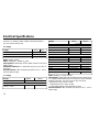
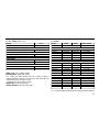
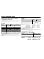
Specifications
General Specifications..........................................21
Electrical Specifications ........................................22
Accessories ................................................................27
Battery Replacement ..................................................28
Fuse Replacement ....................................................29
Repair and Warranty ................................................30
Contents
3

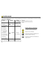
To avoid electrical shock hazard or damage to the meter, do not exceed the overload levels shown below.
* 10A continuous; 20A for 30 seconds maximum, 5 minutes cool down
i n t e r v a l .
Table 1.
Safety
4
Function Terminals Overload Level
d.c. voltage
1000V d.c.
a.c. voltage & COM
V peak
d.c.+a.c. voltage
mV millivolt
ADPAdaptor
Hz Frequency
% Duty Cycle
Ω Resistance & COM 600V d.c. or
nS Conductance V a.c. rms
Audible Continuity
Capacitance
Diode Test
A Current A & COM 10A/600V*
mA or µACurrent mA, µA & COM 630mA/500V
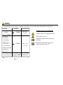
Symbols used on the instrument
Caution: Refer to accompanying notes.
Risk of electric shock.
Equipment complies with relevant EU
Directives
Equipment protected throughout by
Double Insulation (Class II).

5
The M8035 and M 8 0 3 7 are hand-held, battery-
operated professional quality digital multimeters for
t o d a y ’s complex electrical & electronic system diagnostics
and troubleshooting. The M 8 0 3 7 further offers d.c.+a.c.
true RMS responding with wide a.c. bandwidth for non-
sinusoidal waveform measurements, as well as a back-lit
LCD display for all light condition applications.
The measuring functions include d.c. voltage, a.c.
voltage, d.c.+a.c. voltage (M8037 only), dBm (M8037
only), Adaptor Input, Frequency, Duty Cycle, Resistance,
Conductance, Continuity Test, Capacitance, Diode Test,
d.c. current as well as a.c. current.
Pushbutton functions include 4000 Counts Fast
Measuring mode, 40,000 Counts High Resolution
Measuring mode, Data Hold, Auto or Manual Ranging,
Data Store & Recall, Relative Zero mode, Relative %
Change mode, Relative Per Unit mode, 50ms Record
MAX/MIN/MAX-MIN/AVG, 0,8ms Crest MAX/MIN/MAX-
MIN, Sort™ MAX/MIN/MAX-MIN/AVG, dBm Reference
Impedances Selection (M 8 0 3 7 only) as well as
Secondary Functions Selection.
Power on options include Line Filter Frequency 50/60Hz
Selection for best noise rejection (normally only available
in expensive bench top instruments), Auto Power Off
Disable as well as Beeper Disable.
The instruments are housed inside a gasket sealed heavy
duty casing which keeps out grease, oil, dirt and moisture
to maintain superb accuracy and reliability. The casing is
made of high impact thick wall fire retarded material to
maximize durability of the meter, and safety to the user. In
addition, a sealed battery compartment design keeps
battery leakage contaminants off the PCB. T h i s
e ffectively reduces the potential short circuit
contamination risks.
This environmental friendly series contains no CFC
ozone depleting substances, and is not manufactured
with such substances.
General Description

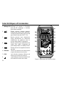
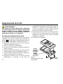
6
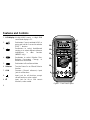
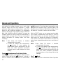
1. LCD display 4
3
⁄4-digit 40000 counts + 4-digit 9999
counts dual display LCD.
2. Pushbutton. Press to activate HOLD, or
press and hold for 1 second to activate
SORT™ function.
3. Pushbutton to select A u t o / M a n u a l
ranging, or to select different reference
impedances in dBm function
(M8037 only).
4. Pushbutton to select Relative Zero,
Relative Percentage Change, or
Relative Per Unit mode.
5. Pushbutton to Recall stored data.
6. Selector Turn the Power On or Off and Select a
function.
7. COM Common (Ground reference) Input
Jack for all functions.
8. Input Jack for all functions ex c e p t
current functions, colour coded.
9. A Input Jack for 4A or 10A c u r r e n t
functions, colour coded.
Features and Controls
®
®
1
214
313
412
511
6
710
89
Figure 1. Front Panel Layout

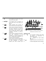
7
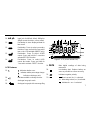
10.mA µA Input Jack for 400mA, 40mA, 4000µAo r
4 0 0 µ A current functions, colour coded.
11 . Pushbutton to store displayed data for
later recall.
1 2 . Pushbutton. Press to select secondary
functions. Press and hold for 1second to
turn on the LCD backlight (M 8 0 3 7o n l y ) .
1 3 . Pushbutton. Press to select 40,000
counts. Press and hold for 1 second to
activate RECORD function.
14. Pushbutton. Press to select 4,000
counts fast mode. Press and hold for
1 second to activate CREST function.
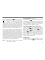
LCD Features
15. indicates relative zero.
indicates relative percentage change.
indicates relative per unit.
16. Indicates audible continuity function.
17. Analogue bar graph scale.
18. Analogue bar graph with overrange flag
and polarity.
1 9 . DATA Main digital readings of data being
measured.
20. Low battery alert. Replace battery as
soon as possible to ensure accuracy.
21. Indicates negative polarity.
22. direct current (d.c.) is selected.
alternating current (a.c.) is selected.
indicates d.c.+a.c. is selected.
Figure 2. LCD (shown actual size)

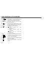
8
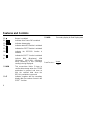
23. Beeper is enabled.
24. Indicates Auto Power Off is enabled.
25. Indicates A u t o r a n g i n g .
26.
Indicates data HOLD function is activated.
27.
Indicates the C R E S T function is activated.
28.
Indicates the RECORD function is
a c t i v a t e d .
29.
Indicates the SORT™ function is activated.
30. Indicate MAX (Maximum), MIN
(Minimum), MAX–MIN (Maximum
minus Minimum), or AVG (Av e r a g e )
reading is being displayed.
31.MEM This annunciator blinks 2 times to
confirm data storage when the STORE
pushbutton is pressed, and turns on
with the recalled data when the
RECALL pushbutton is pressed.
32.# Indicates, together with the secondary
display data, the number of event in the
S O RT™ function.
33.DATA Secondary display for Dual Display data.
Features and Controls
Crest Factor =
V
crest
V
rms

9
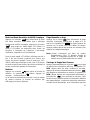
Analogue Bar Graph
The analogue bar graph provides a visual indication of
measurement like a traditional analogue meter needle.
The M8035 and M8037 analogue bar graph updates
up to 128 times per second, showing excellent signal
pattern in detecting faulty contacts, identifying
potentiometer clicks, and indicating signal spikes during
adjustments.
Crest Factor
Crest Factor is the ratio of the Crest (instantaneous peak)
value to the total d.c.+a.c. True RMS value. That is:
A pure sinusoidal waveform has a Crest Factor of 1.414.
A badly distorted sinusoidal waveform normally has a
much higher Crest Factor. If you are measuring a signal
above the DMM’s specified Crest Factor, the DMM may
not produce accurate measurements. M 8 0 3 7 c a n
accurately measure the True RMS value of voltage signal
with a Crest Factor of at least 3.0 at full scale, and 6.0 at
half scale.
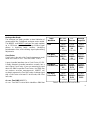
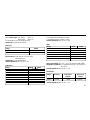
d.c.+a.c.True RMS (M8037)
d.c.+a.c. True RMS is a term which identifies a DMM that
Input d.c.+a.c. a.c. Average
Waveform True rms True rms Response
Sine 1,000V 1,000V 1,000V
ERROR= ERROR= ERROR=
0% 0% 0%
CF=1.414 CF=1.414
Full Wave 1,000V 0.436V 0.412V
Rectified Sine ERROR= ERROR= ERROR=
0% 0% 57.9%
CF=1.414 CF=3.247
Half Wave 0.707V 0.546V 0.550V
Rectified Sine ERROR= ERROR= ERROR=
0% 22.7% 22.2%
CF=2.000 CF=2.591
50% Duty 1,000V 0.707V 0.785V
Pulse Train ERROR= ERROR= ERROR=
0% 29.3% 21.5%
CF=1.414 CF=2.000
Table 2. Waveforms and Crest Factors

10
responds accurately to the total effective RMS value
regardless of the waveform, and is given by the
e x p r e s s i o n :
√d.c.
2
+ (a.c. rms)
2
d.c.+a.c. True RMS voltage is the total effective voltage
having the same heating value corresponding a d.c.
voltage. With d.c.+a.c. True RMS voltage measurement,
you can accurately measure the voltage values regardless
of the waveforms such as: square, sawtooth, triangle, pulse
trains, spikes, as well as distorted waveforms with the
presence of harmonics and d.c. components. Harmonics
and d.c. components may cause:
1) Overheated transformers, generators and motors to
burn out faster than their shelf life
2) Circuit breakers to trip prematurely
3) Fuses to blow
4) Neutrals to overheat due to triple harmonics present
on the neutral
5) Bus bars and electrical panels to vibrate
a.c. only True RMS and Average responding meters can
introduce significant errors in many applications. Table 2
illustrates this.
Bandwidth
Bandwidth of a DMM is the range of frequencies over
which measurements can be made within the specified
accuracy. In other words, a DMM cannot accurately
measure values with frequency spectrums beyond the
frequency response of the DMM. In reality, complex
waveforms, noise and distorted waveforms contain much
higher frequency components than its fundamentals. The
series has bandwidth specifications up to 20kHz in most
ranges, and extended bandwidth specification up to
50kHz on M8037 a.c. 400mV range.
NMRR (Normal Mode Rejection Ratio)
NMRR is the DMM’s ability to reject unwanted a.c. noise
effect which can cause inaccurate d.c. measurements.
NMRR is typically specified in terms of dB (decibels). The
instruments have a NMRR specification of 60dB at 50
and 60Hz, which means the effect of a.c. noise is reduced
more than 1000 times in d.c. measurements.
Features and Controls

11
CMRR (Common Mode Rejection Ratio)
Common mode voltage is voltage present on both the
COM and VOLTAGE input terminals of a DMM, with
respect to ground. CMRR is the DMM’s ability to reject
common mode voltage effects which can cause digit
rattle or offset in voltage measurements.
The instruments have CMRR specifications of 60dB from
d.c. to 60Hz in a.c.V function; and 120dB at d.c., 50 and
60Hz in d.c.V function. If neither NMRR nor CMRR
specification is specified, the DMM’s performance will be
uncertain.
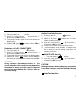
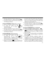
d.c.VOLTAGE function
1) Set rotary switch to position.
2) Insert red (+) test lead into jack and black (–)
test lead into COM input jack.
3) Connect test leads to voltage source and observe the
digital display.
a.c., a.c.+Hz VOLTAGE functions
1) Set rotary switch to position.
2) Insert red (+) test lead into jack and black (–)
test lead into COM input jack.
3) Connect test leads to voltage source and observe the
digital display.
4) Default at a.c. Press button to select a.c.V+Hz
in dual display if required.
d.c., a.c., a.c.+Hz mV functions
1) Set rotary switch to position.
2 ) Default at d . c. Press button to select a . c ., and
press again to select a . c . + H z in dual display
if required.
3) Insert red (+) test lead into jack and black (–)
test lead into COM input jack.
Basic Operation

12
4) Connect test leads to voltage source and observe the
digital display.
d.c.+a.c.VOLTAGE function (M8037 only)
1) Set rotary switch to position.
2) Default at d.c. Press button to select d.c.+a.c.
3) Insert red (+) test lead into jack and black (–)
test lead into COM input jack.
4) Connect test leads to voltage source and observe the
digital display.
dBm+Hz function (M8037 only)
1) Set rotary switch to position.
2) Default at a.c. Press button twice to select
dBm. Default reference impedance 600Ω will be
displayed for 2 seconds before displaying the dBm
and Hz readings.
3) P r e s s button to select different reference
impedances from 4, 8, 16, 32, 50, 75, 93, 110, 125,
135, 150, 200, 250, 300, 500, 600, 800, 900, 1000, up
to 1200Ω. Impedance values will again be displayed
for 2 seconds before displaying the dBm and Hz
readings.
4) Insert red (+) test lead into jack and black (–)
test lead into COM input jack.
5) Connect test leads to signal source and observe the
digital display.
d.c., a.c., a.c.Hz ADAPTOR functions
1) Set rotary switch to position.
2) Default at d.c. Press button to select a.c., and
press again to select a . c . + H z in dual display if
required.
3) Insert output plug of the adaptor with positive (+) into
jack and the negative (–) into COM input jack.
4) The digital display defaults at 10 counts per mV, and
can be extended to 100 counts per mV in 40,000
counts mode.
5) The extra high input impedance of 1000 MΩ allows
the ADP function to cope with most voltage output
adaptors commercially available. For current clamp
adaptor with output 1mV per ampere, 2000 counts on
the digital display represents 200 A. For temperature
adaptor with output 1mV per degree, 2000 counts
represents 200 degrees.
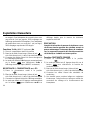
Hz, %+Hz (M8037 only) functions
Basic Operation

13
1) Set rotary switch to position.
2) Insert red (+) test lead into jack and black (–)
test lead into COM input jack.
3) Connect test leads to signal source and observe the
digital display.
4) Default at Hz. Press button to select %+Hz in
dual display (M8037 only).
Resistance, nS+GΩ CONDUCTANCE
1) Set rotary switch to position.
2) Insert red (+) test lead into jack and black (–)
test lead into COM input jack.
3) Connect the test leads and observe the digital display.
4 ) Default at Ω. Press button to select nS+GΩ i n
dual display for resistance measurements beyond 40MΩ.
CAUTION
Using resistance measurement function in a live
circuit will produce false results and may damage the
instrument. In many cases the suspect component
must be disconnected from the circuit to obtain an
accurate reading.
Audible Continuity Function
1) Set rotary switch to position.
2) Default at Ω. Press button twice to select
audible continuity function.
3) Insert red (+) test lead into jack and black (–)
test lead into COM input jack.
4) Connect the test leads to the end points of wire.
5) A continuous beep tone indicates a complete wire.
This is useful for checking wiring connections and
operation of switches
CAPACITANCE function
1) Set rotary switch to position.
2) Insert red (+) test lead into jack and black (–)
test lead into COM input jack.
3) Connect the test leads and observe the digital display.
CAUTION
D i s ch a rge capacitors before making any measurement.
L a rge value capacitors should be disch a rged thro u g h
an appropriate resistive load.
Diode Test Function

14
1) Set rotary switch to position.
2) Default at Capacitance. Press button to
select diode test
3) Insert red (+) test lead into jack and black (–)
test lead into COM input jack.
4) Connect the test leads and observe the digital display.
5) Normal forward voltage drop (forward biased) for a
good silicon diode is between 0.400V to 0.900V. A
reading higher than that indicates a leaky diode
(defective). A zero reading indicates a shorted diode
(defective). An OL indicates an open diode
(defective).
6) Reverse the test leads connections (reverse biased)
across the diode.
7) The digital display shows OL if the diode is good. Any
other readings indicate the diode is resistive or
shorted (defective).
d.c., a.c., a.c.+Hz of µA, mA or A Functions
1) Set rotary switch to A mA or µA
2) Insert red (+) test lead into mA µA jack and black (–)
test lead into C O M input jack for current
measurements below 400mA. Insert red (+) test lead
into A jack and black (–) test lead into COM input jack
for current measurements up to 10A mA or A ranges
will be selected automatically after test leads are
plugged in.
3) Default at d.c. Press button to select a.c., and
press again to select a . c . + H z in dual display if
required.
4) Connect the test leads and observe the digital display.
WARNINGS
Do not measure any circuit that draws more than the
current ratings of the protection fuses. If the fuse
blows, you might be injured or damage the meter.
Do not attempt a current measurement where the
open circuit voltage is above 500V for mA µA jack;
and 600v for A jack. Suspected open circuit voltage
must be checked with voltage functions.
Vo l t a ge output current clamp adaptors are
recommended to use with the meter adaptor or
vo l t age functions for making high current
measurements.
Basic Operation

15
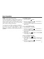
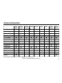
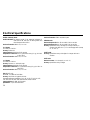
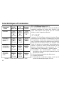
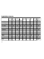
Advanced Operation
Data Range 40,000 Relative Record Crest Sort™ Dual Store
Hold Lock Counts * * * Display Recall
d.c.Voltage ● ● ● ● ● ● ● ●
a.c.Voltage ● ● ● ● ● ● ● ● ●
d.c.+a.c.Voltage ● ● ● ● ● ● ● ●
d.c. Current ● ● ● ● ● ● ● ●
a.c. Current ● ● ● ● ● ● ● ● ●
Resistance ● ● ● ● ● ● ●
Conductance ● ● ● ●
Frequency ● ●
Duty Cycle ● ● ●
Capacitance ● ● ● ● ● ●
Adaptor ● ● ● ● ● ● ● ●
dBm ● ● ● ● ●
Continuity ● ● ●
Diode ● ●
Table 3. Feature Availability Summary
* Note: RECORD, CRESTand SORT™ are not available in Dual Display mode.

16
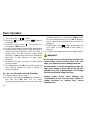
40,000 Counts High Resolution Mode
Press the button momentary to enter the 4
3
⁄4-digit
high resolution mode with a maximum display at
40,000 counts. Press the button to return to
3
3
⁄4-digit fast mode. The 4
3
⁄4-digit mode is available in all
functions except Frequency, Duty Cycle, Capacitance
and Diode Test.
In 3
3
⁄4-digit fast mode, the digital display nominally
updates 5 times per second to give you the maximum
measuring speed. In 4
3
⁄4-digit mode, the digital display
updates 1.25 times per second nominal to give you
smooth readings as well as the full accuracy of the meter.
Hold
Press the button to activate the hold function. T h e
a n n u n c i a t o r turns on in the LCD. Press again to
release. When in normal measuring modes, the hold
feature freezes the display for later viewing. When in
record or crest mode, however, the hold function stops
updating the measurements, and you can read throughout
the locked MAX, MIN, MAX-MIN, and AVG readings.
Release the hold function to continue record or crest.
Manual or Auto Ranging
Press the button to select manual ranging, and the
meter will remain in the range it was in when the LCD
annunciator turns off. Press the button again to
step through the ranges. Press and hold the button for
1 second or more to resume auto ranging.
Note: When the meter is in Record, Crest, Sort™, Hold,
Recall or Relative modes, changing the measuring
range manually will cause the meter to exit those
features.
Data Store & Recall
Press the button to store the displayed information.
The LCD annunciator MEM blinks twice to confir m
storage. Press the button to recall the stored data;
the LCD annunciator MEM turns on. Press any other
buttons ex c e p t to resume measurements. T h i s
feature stores the whole display data in memory for later
recall. The memory will remain even in auto-power-off
mode, and can also be recalled while you are in another
meter function. The memory will be erased if the rotary
switch is switched to the OFF position.
Advanced Operation

17
Relative Modes
Press the button to enter the Relative Zero ( )
mode. The LCD annunciator turns on. Relative zero
allows the user to offset the meter measurements with a
relative reference value. Practically all displayed readings
can be set as relative reference value including MAX,
MIN, MAX-MIN, and AVG readings of RECORD or
SORT™ functions.
Press the button again to enter the Relative
Percentage Change ( ) mode. The LCD annunciators
turn on. In this mode, the readings show relative
percentage changes, and the bar graph automatically
indicates ±200%, or ±20% full scale changes with respect
to the relative reference value as centre zero point. It
simplifies zero, peaking, nulling measurements, and is
excellent for fine adjustments.
Press the button again to enter the Relative Per
Unit (U) mode. The LCD annunciators turn on.
This is a unique feature to show the ratio of measuring
values to the relative base value. The relative base value
is considered to be one unit, and the consecutive
measurements will be displayed in terms of units.
Measuring the parallel capacitance of co-axial cable or
parallel wires in conjunction with the relative per unit
mode, for example, helps in estimating the total cable
length or locating cable breakage locations.
Press and hold the button for 1 second or more to
exit relative modes and resume normal measurements.
Record Mode
Perform measurements as described in the Basic
Operation section. Press and hold the button for
1 second or more to activate RECORD mode, with the
LCD annunciators turned on. The meter beeps
when maximum or minimum reading is updated. Press
t h e button momentarily to cycle through the
Maximum (MAX), Minimum (MIN), Maximum minus
Minimum (MAXMIN), and Average (AVG) readings. Press
the button for 1 second or more to exit record mode.
With the Auto-Ranging RECORD mode, you can easily
track intermittent signals, capture turn-on/turn-off surges,

18
and monitor line voltage changes over a much wider
dynamic range with the best resolution. It largely
surpasses single range recording which is easily over-
flowed, or with insufficient resolution. The instruments
feature a fast single range sampling speed of 50ms for
MAX, MIN, MAX-MIN and AVG readings. The faster the
sampling speed, the more accurate the measurement of
surges, spikes and sags will be. The true average AVG
feature calculates all readings taken over time
continually.
Note: 1. Auto Power Off feature is disabled
automatically in this mode.
2. To retain the readings after measurements,
u s e function to stop updating the
measurements before disconnecting the test
leads. Use similar pushbutton procedures
described above to read throughout the locked
r e a d i n g s .
Crest (Instantaneous Peak Value) Mode
Perform measurements as described in Basic Operation
section. Press and hold the button for 1 second or
more to activate crest mode with LCD annunciators
MAX turned on. Press the button momentarily to read
throughout the Maximum (MAX), Minimum (MIN), and
Maximum minus Minimum (MAX-MIN) readings. Press
the button for 1 second or more to exit crest mode.
With the CREST mode, you can capture transient signal
crest voltage (instantaneous peak value) as short as
0.8ms. This function can be used to determine crest
factor which can indicate the presence of harmonics.
Crest factor is the ratio of crest value to the true rms
value. A pure sinusoidal waveform has a crest factor of
1.414.
Note: 1. Auto Power Off feature is disabled
automatically in this mode.
2. To retain the readings after measurements,
u s e function to stop updating the
measurements before disconnecting the test
leads. Use similar pushbutton procedures
described above to cycle through the locked
readings.
Sort™ Mode
Perform measurements as described in Basic Operation
Advanced Operation

19
section. Press and hold the button for 1 second or
more to activate SORT™ mode with LCD annunciators
turned on. The meter beeps when a stable
reading is captured, and the last captured reading,
together with a counter, will be automatically held and
displayed. Press the button momentarily to cycle through
the Maximum (MAX), Minimum (MIN), Maximum minus
Minimum (MAX-MIN), and Average (AVG) readings. Press
the button for 1 second or more to exit SORT™ mode.
S O R T™ senses a stable measurement, beeps, captures it
for comparison & display, then stores the maximum and
minimum readings, together with the event numbers, in
memory for later display. The average feature calculates all
the readings taken and displays the true average value
together with the number of events counted. This simplifie s
MAX and MIN values sorting, MAX-MIN & AVG values
calculation, and quantity counting in component inspection.
When used with relative % change function, readings will
be displayed in terms of percentage deviation.
Note: 1. Auto Power Off feature will be disabled
automatically in this mode.
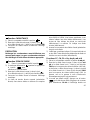
Back Light Feature (M8037 only)
Press and hold the button for 1 second or more to
activate backlight. The backlight will automatically switch
off 42 seconds after each activation to extend battery life.
When the backlight is already on, press and hold the
button again to reset the automatic off timing.
Line Filter Frequency 50 Hz or 60 Hz Select
The line filter frequency can be selected as a power-on
option. Press the button while turning the meter on
to display the set frequency. Press the button for
50 Hz or press the button for 60 Hz selection. Then
press the button to store the selected frequency.
Selecting the appropriate line filter frequency to cope with
your line frequency can maximize the meter’s noise
rejection ability. This is normally only available in
expensive bench-top multimeters.
Set Beeper Off
The beeper feature can be disabled manually as a power-
on option by pressing the button while turning the

20
meter on. The LCD annunciator will be off during
operation. All beeper functions are turned off except input
warning beeper.
Auto Power Off
The Auto Power Off mode automatically turns the meter
off after 4.5 minutes of inactivity to extend battery life. The
meter turns back on if the rotary switch is turned.
Activities are specified as:
1) Rotary switch or push button operations.
2) Significant measuring data readings.
When entering the RECORD, CREST or SORT™ mode,
Auto Power Off is disabled automatically, and the LCD
annunciator is off.
The Auto Power Off feature can be disabled manually as
a power-on option by pressing the button while
turning the meter on. The LCD annunciator will be
off during operation.
For maintenance purposes, the Auto Power Off timing
can be shortened to 5 seconds by pressing the
button while turning the meter on.
Note: 1. Stored data (MEM) remains after Auto
Power Off, but will be erased if the rotary
switch is switched to the OFF position.
2. Always turn the rotary switch to the OFF
position when the meter is not in use. The
meter will produce a beep sound while
turning off to alert the user.
Input Warning
If improper connections are made to the meter for the
range selected, the beeper will continue to sound and the
display will indicate “InErr” to warn the user against
possible damage.
Advanced Operation
La page est en cours de chargement...
La page est en cours de chargement...
La page est en cours de chargement...
La page est en cours de chargement...
La page est en cours de chargement...
La page est en cours de chargement...
La page est en cours de chargement...
La page est en cours de chargement...
La page est en cours de chargement...
La page est en cours de chargement...
La page est en cours de chargement...
La page est en cours de chargement...
La page est en cours de chargement...
La page est en cours de chargement...
La page est en cours de chargement...
La page est en cours de chargement...
La page est en cours de chargement...
La page est en cours de chargement...
La page est en cours de chargement...
La page est en cours de chargement...
La page est en cours de chargement...
La page est en cours de chargement...
La page est en cours de chargement...
La page est en cours de chargement...
La page est en cours de chargement...
La page est en cours de chargement...
La page est en cours de chargement...
La page est en cours de chargement...
La page est en cours de chargement...
La page est en cours de chargement...
La page est en cours de chargement...
La page est en cours de chargement...
La page est en cours de chargement...
La page est en cours de chargement...
La page est en cours de chargement...
La page est en cours de chargement...
La page est en cours de chargement...
La page est en cours de chargement...
La page est en cours de chargement...
La page est en cours de chargement...
La page est en cours de chargement...
La page est en cours de chargement...
La page est en cours de chargement...
-
 1
1
-
 2
2
-
 3
3
-
 4
4
-
 5
5
-
 6
6
-
 7
7
-
 8
8
-
 9
9
-
 10
10
-
 11
11
-
 12
12
-
 13
13
-
 14
14
-
 15
15
-
 16
16
-
 17
17
-
 18
18
-
 19
19
-
 20
20
-
 21
21
-
 22
22
-
 23
23
-
 24
24
-
 25
25
-
 26
26
-
 27
27
-
 28
28
-
 29
29
-
 30
30
-
 31
31
-
 32
32
-
 33
33
-
 34
34
-
 35
35
-
 36
36
-
 37
37
-
 38
38
-
 39
39
-
 40
40
-
 41
41
-
 42
42
-
 43
43
-
 44
44
-
 45
45
-
 46
46
-
 47
47
-
 48
48
-
 49
49
-
 50
50
-
 51
51
-
 52
52
-
 53
53
-
 54
54
-
 55
55
-
 56
56
-
 57
57
-
 58
58
-
 59
59
-
 60
60
-
 61
61
-
 62
62
-
 63
63


Megger M8035 Manuel utilisateur
- Catégorie
- Mesure, test
- Taper
- Manuel utilisateur
- Ce manuel convient également à
dans d''autres langues
- English: Megger M8035 User manual
Documents connexes
Autres documents
-
Beta 1760PA/AC Mode d'emploi
-
Amprobe AM-52, AM-57 & AM-59 Digital Multimeters Manuel utilisateur
-
Extech Instruments MM560A Manuel utilisateur
-
Power Fist 8637316 Le manuel du propriétaire
-
Greenlee CLAMP-ON GROUND RESISTANCE TESTER Manuel utilisateur
-
-
Tektronix DMM912 Instructions For Use Manual
-
 Chauvin-Arnoux CA6511 Le manuel du propriétaire
-
-
