Power Fist 8637316 Le manuel du propriétaire
- Catégorie
- Mesure, test
- Taper
- Le manuel du propriétaire

V4.0 8637316
Please read and understand all instructions before use. Retain this manual for
future reference.
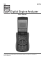
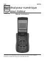
Digital Engine Analyzer
User Manual

8637316 Digital Engine Analyzer V4.0
2 For technical questions call 1-800-665-8685
SPECIFICATIONS
Device
CAT Rating CAT II
Automatic Power Off Yes
Reading Rate 3 Readings Per Second
Display 3-3/4 Digit LCD
Battery Single 9V Battery (NEDA 1604 or IEC6F22)
Fuses 0.5A/250V, 5 x 20 mm
10A/250 5 x 20 mm
Operating Temperature 32 to 122 ºF (0 to 50 ºC)
Storage Temperature -4 to 140 ºF (-20 to 60 ºC)
Ranges
AC Voltage Range
400mV to 750V
DC Voltage Range
400mV to 1,000V
AC Current Range 40mA to 10A
DC Current Range 40mA to 10A
Resistance 400Ω to 20MΩ
Capacitance 40nF to 100µF
Frequency 100Hz to 200KHz
Duty Cycle 0.1% to 99.9%
Temperature -4 to 1,832 ºF (-20 to 1,000 ºC)
INTRODUCTION
Automotive diagnostic tool used for measuring DC/AC voltage and current,
resistance, capacitance, frequency and duty cycle, temperature, diode/continuity
test and dwell.
Digital Engine Analyzer

V4.0 Digital Engine Analyzer 8637316
Visit www.princessauto.com for more information 3
SAFETY
WARNING! Read and understand all instructions before using this tool. The
operator must follow basic precautions to reduce the risk of personal injury
and/or damage to the equipment.
Keep this manual for safety warnings, precautions, operating or inspection and
maintenance instructions.
HAZARD DEFINITIONS
Please familiarize yourself with the hazard notices found in this manual. A notice
is an alert that there is a possibility of property damage, injury or death if certain
instructions are not followed.
DANGER! This notice indicates an immediate and specific hazard that will
result in severe personal injury or death if the proper precautions
are not taken.
WARNING! This notice indicates a specific hazard or unsafe practice that
could result in severe personal injury or death if the proper
precautions are not taken.
CAUTION! This notice indicates a potentially hazardous situation that may result
in minor or moderate injury if proper practices are not taken.
NOTICE! This notice indicates that a specific hazard or unsafe practice will
result in equipment or property damage, but not personal injury.
WORK AREA
1. Operate in a safe work environment. Keep your work area clean, well-lit
and free of distractions.
2. Keep anyone not wearing the appropriate safety equipment away from the
work area.
3. Store unused tools properly in a safe and dry location to prevent rust or
damage. Lock tools away and keep out of the reach of children.
4. Do not install or use in the presence of flammable gases, dust or liquids.

8637316 Digital Engine Analyzer V4.0
4 For technical questions call 1-800-665-8685
PERSONAL SAFETY
WARNING! Wear personal protective equipment approved by the Canadian
Standards Association (CSA) or American National Standards Institute (ANSI).
PERSONAL PROTECTIVE EQUIPMENT
1. Always wear impact safety goggles that provide front and side protection
for the eyes. Eye protection equipment should comply with CSA Z94.3-07
or ANSI Z87.1 standards based on the type of work performed.
2. Wear gloves that provide protection based on the work materials or to
reduce the effects of tool vibration.
3. Wear protective clothing designed for the work environment and tool.
4. Non-skid footwear is recommended to maintain footing and balance in the
work environment.
PERSONAL PRECAUTIONS
Control the tool, personal movement and the work environment to avoid
personal injury or damage to tool.
1. Do not operate any tool when tired or under the influence of drugs, alcohol
or medications.
2. Avoid wearing clothes or jewelry that can become entangled with the
moving parts of a tool. Keep long hair covered or bound.
SPECIFIC SAFETY PRECAUTIONS
WARNING! DO NOT let comfort or familiarity with product (gained from
repeated use) replace strict adherence to the tool safety rules. If you use
this tool unsafely or incorrectly, you can suffer serious personal injury.
1. Use the correct tool for the job. This tool was designed for a
specific function. Do not modify or alter this tool or use it for
an unintended purpose.
2. Inspect the test leads for damaged insulation or exposed metal. Check for
continuity. Replace damaged test leads before using the meter.
3. Do not use the meter if it malfunctions. Protective features may be
impaired. When in doubt, have the meter serviced.

V4.0 Digital Engine Analyzer 8637316
Visit www.princessauto.com for more information 5
4. Do not apply more than 1,000V DC or 750V AC rms between terminals, or
between any terminal and earth ground.
5. Do not exceed the Overload Protection values specified on the tables
following each measuring process. Exceeding the safety limits could result
in electric shock or damage to the meter.
6. Do not touch a naked conductor with your hand or exposed skin to prevent
electric shock. Do not ground yourself while using the meter.
7. Circuits tested must be protected by a 10A fuse or a circuit breaker.
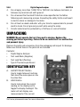
UNPACKING
WARNING! Do not operate the tool if any part is missing. Replace the
missing part before operating. Failure to do so could result in a malfunction
and personal injury.
Remove the parts and accessories from the packaging and inspect for damage.
Make sure that all items in the parts list are included.
Contents:
• Digital Engine Analyzer
• Test Lead Black (Negative)
• Test Lead Red (Positive)
• Type K Thermocouple Sensor
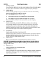
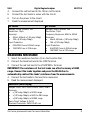
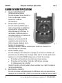
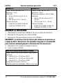
IDENTIFICATION KEY
A. Hz/DUTY/SELECT Button
Use to toggle between functions
that share the same space on the
Function Dial.
B. HOLD Button
Use to lock/unlock the current
reading on the display and to
toggle the display backlight. The
meter will not display new
measurements if the current
Fig. 1

8637316 Digital Engine Analyzer V4.0
6 For technical questions call 1-800-665-8685
reading is locked.
Press the HOLD Button to lock the current reading. Press the button again
to unlock. Press and hold the button to toggle the display backlight.
C. RANGE Button
Use to manually specify a range or to allow the meter to automatically
select the best range for a specific function.
Press the RANGE button to enter a range.
• If the range is too high, the reading will be less accurate.
• If the range is too low, the meter will display OL (over limit).
Press and hold the button for two seconds to use auto-ranging.
D. REL BUTTON
Use to automatically calculate the difference between two readings.
Press the REL Button to enter relative measuring mode. The present
reading will be used as a reference value. The meter will display the
difference between the value of the new readings and the reference value.
Press the button again to exit relative measuring mode.
E. Function Dial
Use to select a function or turn the unit off.
Rotate the dial, either clockwise or counterclockwise, to select the desired
function. Multiple functions share the same space on the dial. Use the
SELECT Button to toggle between them.
F. 10A Terminal
Plug-in connector for the red test lead. Use to measure current.
CAUTION! The terminal is protected by a fuse. Only test circuits that are
limited to 10A for a maximum of 15 seconds to prevent electric shock or
damage to the meter.
G. COM Terminal
Plug-in connector for the black test lead.
H. V/Ω/RPM/K+ Terminal
Plug-in connector for the red test lead. Use to measure voltage, resistance,
capacitance, frequency, duty cycle, temperature, diode/continuity test,
dwell and pulse width.

V4.0 Digital Engine Analyzer 8637316
Visit www.princessauto.com for more information 7
I. mA/K- Terminal
Plug-in connector for the red test lead. Use to measure current
and temperature.
CAUTION! The terminal is protected by a fuse. Only test circuits that are
limited to 400mA for a maximum of 15 seconds to prevent electric shock or
damage to the meter.
OPERATION
MEASUREMENT INSTRUCTIONS
CAUTION! Keep your fingers behind the guards on the test leads. Do not
touch the lead tips or the circuit being tested to prevent electric shock.
CAUTION! Do not connect more than one set of test leads to the meter to
prevent electric shock or damage to the meter.
1. Measure a known voltage or current before using the meter to verify if it is
functioning properly.
2. Turn off all power to the circuit and fully discharge all capacitors before
measuring resistance, capacitance, diode or continuity. Residual voltage
charges on the capacitor, poor insulation resistance and poor dielectric
absorption may affect measurement accuracy.
3. Use the proper terminals, function and range for your measurements.
4. When connecting the test leads to a terminal, connect the common test
lead first and the live test lead second. Reverse the order when
disconnecting (live test lead first, common test lead second).
5. Disconnect the test leads from the circuit under test before using the
Function Dial to switch to a different function.
6. The meter’s accuracy is specified for a period of one year after calibration
at 65 to 83 ºF (18 to 28 ºC) with relative humidity up to 70%. The tables
following each measuring process display the accuracy specifications in
the following form: ±[(% of rdg)+(dgt)], where rdg = Reading and dgt =
Number of Least Significant Digits.

8637316 Digital Engine Analyzer V4.0
8 For technical questions call 1-800-665-8685
MEASURING VOLTAGE
CAUTION! Do not connect the test leads to the 10A or mA terminal when
measuring voltage to prevent electric shock or damage to the meter.
1. Select the voltage function (V) on the Function Dial.
2. Press the SELECT Button to toggle between DC and AC.
3. Connect the black test lead to the COM Terminal.
4. Connect the red test lead to the V/Ω/RPM/K+ Terminal.
5. Connect the test leads to the circuit to be measured.
6. Read the measurement displayed.
DC Voltage (Auto-ranging) AC Voltage (Auto-ranging)
Ranges: 400mV, 4V, 40V, 400V, 1,000V
Accuracy:
• 400mV ±(2.5%rdg+15dgt)
• 4V, 40V, 400V, 1,000V
±(0.8%rdg+8dgt)
Resolution: 100µV
Input Impedance: >10MΩ
Overload Protection: 1,000V DC or 750V
AC rms
Ranges: 400mV, 4V, 40V, 400V, 750V
Accuracy:
• 400mV ,750V ±(3.0%rdg+15dgt) at
50Hz to 100Hz
• 4V, 40V, 400V, ±(1.5%rdg+15dgt) at
50Hz to 400Hz
Resolution: 100µV
Input Impedance: >10MΩ
Overload Protection: 1,000V DC or 750V
AC rms
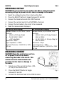
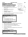
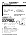
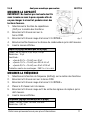
MEASURING CURRENT
CAUTION! Check the meter’s fuse and turn
off all power to the circuit before
connecting the leads to the circuit. This
ensures accurate measurements and
prevents electric shock or damage to
the meter.
1. Select one of the current functions (10A
or mA) on the Function Dial.
2. Press the SELECT Button to toggle
between DC and AC.
3. Connect the black test lead to the COM Terminal.
Fig. 2

V4.0 Digital Engine Analyzer 8637316
Visit www.princessauto.com for more information 9
4. Connect the red test lead to the 10A or mA Terminal.
5. Connect the test leads in series with the circuit.
6. Turn on the power to the circuit.
7. Read the measurement displayed.
MEASURING RESISTANCE
1. Select the resistance function (Ω) on the Function Dial.
2. Connect the black test lead to the COM Terminal.
3. Connect the red test lead to the V/Ω/RPM/K+ Terminal.
IMPORTANT! The resistance of the test leads can affect accuracy at 400Ω
range. Connect the leads together and press the REL Button to
automatically subtract the leads’ resistance from the measurements.
4. Connect the test leads to the load to be measured.
5. Read the measurement displayed.
Resistance (Auto-ranging)
Ranges: 400Ω, 4KΩ, 40KΩ, 400KΩ, 4MΩ, 20MΩ
Accuracy:
• ±(1.5%rdg+15dgts) at 400Ω range
• ±(1.0%rdg+10dgts) at 4KΩ to 4MΩ range
• ±(2.5%rdg+15dgts) at 40MΩ range
Open Circuit Voltage: 0.4V DC
Overload Protection: 250V DC/AC rms
DC Current AC Current
Ranges: 40mA, 400mA, 10A
Resolution: 10µA
Accuracy:
• 40mA, 400mA ±(1.5%rdg+10dgt)
• 10A ±(2.0%rdg+15dgt)
Input Protection:
• 0.5A/250V fuse at 400mA range
• 10A/250V fuse at 10A range
Ranges: 40mA, 400mA, 10A
Resolution: 10µA
Frequency Response: 50Hz to 400Hz
Accuracy:
• 40mA, 400mA ±(1.8%rdg+15dgt)
• 10A ±(2.5%rdg+15dgt)
Input Protection:
• 0.5A/250V fuse at 400mA range
•
10A/250V fuse at 10A range

8637316 Digital Engine Analyzer V4.0
10 For technical questions call 1-800-665-8685
MEASURING CAPACITANCE
IMPORTANT! Do not touch the lead tips with
your hand or exposed skin to avoid charging
the circuit and generating false readings.
1. Select the capacitance function (CAP) on the
Function Dial.
2. Connect the black test lead to the
COM Terminal.
3. Connect the red test lead to the
V/Ω/RPM/K+ Terminal.
4. Connect the test leads to the capacitor terminals to be measured.
5. Read the measurement displayed.
Capacitance (Auto-ranging)
Ranges: 40nF, 400nF, 4µF, 40µF, 100µF
Resolution: 10pF
Accuracy:
• ±(2.5%rdg+10dgts) at 40nF range
• ±(1.5%rdg+10dgts) at 400nF to 4uF ranges
• ±(2.5%rdg+15dgts) at 40uF to 100uF ranges
Overload Protection: 250V DC/AC rms
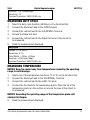
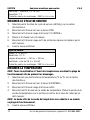
MEASURING FREQUENCY
1. Select the frequency function (Hz/Duty) on the Function Dial.
2. Connect the black test lead to the COM Terminal.
3. Connect the red test lead to the V/Ω/RPM/K+ Terminal.
4. Ground the black test lead.
5. Connect the red test lead to the Signal Out wire of the sensor to
be measured.
6. Read the measurement displayed.
Frequency (Auto-ranging)
Ranges: 100Hz, 1KHz, 100KHz, 200KHz
Resolution: 0.01Hz
Fig. 3

V4.0 Digital Engine Analyzer 8637316
Visit www.princessauto.com for more information 11
Accuracy: ±(0.1%rdg+5dgts)
Sensitivity: 1V
Overload Protection: 250V DC/AC rms
MEASURING DUTY CYCLE
1. Select the duty cycle function (Hz/Duty) on the Function Dial.
2. Connect the black test lead to the COM Terminal.
3. Connect the red test lead to the V/Ω/RPM/K+ Terminal
4. Ground the black test lead.
5. Connect the red test lead to the Signal Out wire of the sensor to
be measured.
6. Read the measurement displayed.
Duty Cycle
Ranges: 0.1 to 99.9%
Resolution: 0.1%
Pulse Width : >100us, <100ms
Accuracy: ±(2.5%rdg+10dgt)
Overload Protection: 250V DC/AC rms
MEASURING TEMPERATURE
NOTICE! Keep the meter away from temperatures exceeding the operating
range to avoid damage.
1. Select one of the temperature functions (ºC or ºF) on the Function Dial.
2. Connect the black test lead to the V/Ω/RPM/K+ Terminal.
3. Connect the red test lead to the mA/K- Terminal.
4. Connect the test leads to the temperature probe. Place the tip of the
temperature probe on the surface or around the area of the object to
be measured.
NOTICE! Exceeding the operating range of the temperature probe will
shorten its lifespan.
5. Read the measurement displayed.

8637316 Digital Engine Analyzer V4.0
12 For technical questions call 1-800-665-8685
Temperature
Ranges: -4 to 1,832 ºF (-20 to 1,000 ºC)
Resolution: 1 ºC/F
Accuracy:
• ±(1%rdg+4 ºF)
• ± (1%rdg+2 ºC)
Sensor: Type K Thermocouple
Input Protection: 60V DC or 24V AC rms
TESTING DIODE
1. Select the diode test function ( ) on the Function Dial.
2. Connect the black test lead to the COM Terminal.
3. Connect the red test lead to the V/Ω/RPM/K+ Terminal.
4. Connect the black test lead to the cathode (-) and the red test lead to the
anode (+). Read the measurement displayed.
5. Switch the positions of the test leads; black test lead to the anode (+), red
test lead to the cathode (-). Read the measurement displayed.
A working diode will have one measurement higher than the other. A defective
diode will have the same measurements on both readings, or has
measurements in the 1.0 to 3.6V range on both readings.
Diode Test
Test Condition:
• Forward DC current approx. 1.5mA
• Reversed DC voltage approx. 1.5V
Overload Protection: 250V DC/AC rms
TESTING CONTINUITY
1. Select the continuity test function ( ) on the Function Dial.
2. Connect the black test lead to the COM Terminal.
3. Connect the red test lead to the V/Ω/RPM/K+ Terminal.
4. Connect the test leads to the circuit under test.
5. The meter will beep to indicate that the circuit is closed. The meter will not
beep and display OL to indicate that the circuit is open.

V4.0 Digital Engine Analyzer 8637316
Visit www.princessauto.com for more information 13
Continuity Test
Open Circuit Voltage: 0.4V DC
≤60Ω Meter Beeps
Overload Protection: 250V DC/AC rms.
MEASURING DWELL
1. Select one of the dwell functions (4CYL, 5CYL, 6CYL, 8CYL) on the
Function Dial.
2. Connect the black test lead to the COM Terminal.
3. Connect the red test lead to the V/Ω/RPM/K+ Terminal.
4. Ground the black test lead.
5. Connect the red test lead to the signal wire that connects to the
breaker points.
6. Read the measurement displayed.
Dwell Angle
# of Cylinders 4 5 6 8
Range 0 to 90º 0 to 72º 0 to 60º 0 to 45º
Resolution: 0.1º
Accuracy: ±(2.5%rdg+10dgt)
Overload Protection: 250V DC/AC rms
MEASURING PULSE WIDTH
1. Select the pulse width function (ms PULSE) on the Function Dial.
2. Connect the black test lead to the COM Terminal.
3. Connect the red test lead to the V/Ω/RPM/K+ Terminal.
4. Ground the black test lead.
5. Connect the red test lead to the signal wire that connects to the object to
be measured.
6. Read the measurement displayed.

8637316 Digital Engine Analyzer V4.0
14 For technical questions call 1-800-665-8685
Pulse Width
Range: 0.1ms to 10.0ms
Accuracy: ±(2.5%+0.2ms)
Overload Protection: 250V DC/AC rms
CARE & MAINTENANCE
1. Maintain the tool with care. A tool in good condition is efficient, easier to
control and will have fewer problems.
2. Inspect the tool components periodically. Repair or replace damaged or
worn components. Only use identical replacement parts when servicing.
3. Rotate the Function Dial to the OFF position when not in use to extend
battery life. If storing for an extended period of time, remove the batteries
from the case.
4. Replace the battery as soon as the low battery indicator ( ) appears.
5. Only use accessories intended for use with this tool.
6. Keep the tool handles clean, dry and free from oil/grease at all times.
7. Maintain the tool’s labels and name plates. These carry important information.
If unreadable or missing, contact Princess Auto Ltd. for replacements.
WARNING! Only qualified service personnel should repair the tool. An
improperly repaired tool may present a hazard to the user and/or others.
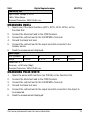
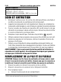
REPLACING THE BATTERY AND FUSE
CAUTION! Remove the test leads from the meter and turn the meter off
before opening the cover or case. Ensure that the cover or case is closed
and secure before using the meter again.
1. Remove the four screws securing the back cover to the case.
2. Remove the cover by lifting it up and away from the case.
3. To replace the battery:
a. Remove the old battery from the battery holder.
b. Check the battery holder for polarity symbols.
c. Install a new battery of the same type.

V4.0 Digital Engine Analyzer 8637316
Visit www.princessauto.com for more information 15
4. To replace the fuse:
a. Firmly grasp the edges of the circuit board and lift it up and away from
the case.
IMPORTANT! Ensure that your hands are clean before touching the circuit
board. A dirty circuit board may lead to erratic meter readings.
b. Remove the old fuse from the fuse holder.
c. Install a new fuse of the same type.
d. Reseat the circuit board.
5. Mount the cover onto the case and secure using the four screws.
DISPOSAL
Recycle a tool damaged beyond repair at the appropriate facility.
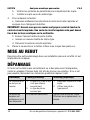
TROUBLESHOOTING
Visit a Princess Auto Ltd. location for a solution if the tool does not function
properly or parts are missing. If unable to do so, have a qualified technician
service the tool.
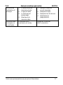
Problem(s) Possible Cause(s) Suggested Solution(s)
Meter does not
turn on.
1. Battery or battery wire is
not seated properly.
2.
Battery type is incorrect.
1. Reseat battery or
battery wire.
2.
Use correct battery type.
Ampere reading
is erratic or not
available.
Fuse is faulty. Check fuse for continuity.
Replace if necessary.
Meter reading
is erratic.
1. Circuit board is dirty.
2. Battery is low.
3. Test lead is damaged.
4. Wrong range selected.
1. Clean circuit board.
2. Replace battery.
3. Replace test leads.
4. Select correct range.
Meter reading
does not change.
HOLD feature is toggled on. Toggle off HOLD feature.

V 4,0 8637316
Vous devez lire et comprendre toutes les instructions avant d'utiliser l'appareil.
Conservez ce manuel afin de pouvoir le consulter plus tard.
Manuel d'utilisateur
Analyseur numérique
pour moteur

8637316 Analyseur numérique pour moteur V 4,0
2 En cas de questions techniques, appelez le 1-800-665-8685
SPÉCIFICATIONS
Dispositif
Niveau CAT CAT II
Arrêt automatique Oui
Rythme de lecture 3 lectures par seconde
Affichage ACL, 3 3/4 chiffres
Pile Pile unique de 9 V (NEDA 1604 ou
IEC6F22)
Fusibles 0,5 A/250 V, 5 x 20 mm
10 A/250 V, 5 x 20 mm
Température de fonctionnement
0 à 50 ºC (32 à 122 ºF)
Température d'entreposage
-20 à 60 ºC (-4 à 140 ºF)
Plages
Plage de tension c.a. 400 mV à 750 V
Plage de tension c.c. 400 mV à 1 000 V
Plage de courant c.a. 40 mA à 10 A
Plage de courant c.c. 40 mA à 10 A
Résistance 400 Ω à 20 MΩ
Capacité 40 nF à 100 µF
Fréquence 100 Hz à 200 KHz
Cycle de service 0,1 % à 99,9 %
Température -20 à 1 000 ºC (-4 à 1 832 ºF)
INTRODUCTION
Outil de diagnostic pour automobile servant à mesurer la tension c.c./c.a. et le
courant, la résistance, la capacitance, la fréquence, le cycle de service, la température,
les diodes et la continuité, le temps de maintien et la puissance des signaux.
Analyseur numérique
pour moteur

V 4,0 Analyseur numérique pour moteur 8637316
Visitez www.princessauto.com pour plus d'informations 3
SÉCURITÉ
AVERTISSEMENT ! Veuillez lire et comprendre toutes les instructions avant
d'utiliser cet outil. L'utilisateur doit respecter les précautions de base
lorsqu'il utilise cet outil afin de réduire le risque de blessure ou de
dommage à l'équipement.
Conservez ce manuel qui contient les avertissements de sécurité, les
précautions, les instructions de fonctionnement ou d'inspection et d'entretien.
DÉFINITIONS DE DANGER
Veuillez-vous familiariser avec les avis de danger qui sont présentés dans ce
manuel. Un avis est une alerte indiquant qu'il existe un risque de dommage à la
propriété, de blessure ou de décès si on ne respecte pas certaines instructions.
DANGER ! Cet avis indique un risque immédiat et particulier qui
entraînera des blessures corporelles graves ou même la
mort si on omet de prendre les précautions nécessaires.
AVERTISSEMENT ! Cet avis indique un risque particulier ou une pratique non
sécuritaire qui pourrait entraîner des blessures
corporelles graves ou même la mort si on omet de
prendre les précautions nécessaires.
ATTENTION ! Cet avis indique une situation possiblement dangereuse qui
peut entraîner des blessures mineures ou modérées si on
ne procède pas de la façon recommandée.
AVIS ! Cet avis indique un risque particulier ou une pratique non
sécuritaire qui entraînera des dommages au niveau de
l'équipement ou des biens, mais non des blessures corporelles.
AIRE DE TRAVAIL
1. Travaillez dans un environnement de travail sécuritaire. Gardez votre aire
de travail propre, bien éclairée et exempte de toute distraction.
2. Assurez-vous que les personnes qui ne portent pas l'équipement de
sécurité approprié ne se trouvent pas à proximité de l'aire de travail.
3. Rangez les outils correctement dans un lieu sécurisé et sec. Gardez les
outils hors de la portée des enfants.

8637316 Analyseur numérique pour moteur V 4,0
4 En cas de questions techniques, appelez le 1-800-665-8685
4. N'installez pas et n'utilisez pas d'outils électriques en présence de gaz, de
poussière ou de liquides inflammables.
SÉCURITÉ PERSONNELLE
AVERTISSEMENT ! Portez de l'équipement de protection personnelle
homologué par l'Association canadienne de normalisation (CSA) ou
l'American National Standards Institute (ANSI).
ÉQUIPEMENT DE PROTECTION PERSONNELLE
1. Portez toujours des lunettes antiprojections qui offrent une protection
frontale et latérale pour les yeux. L'équipement de protection des yeux
devrait être conforme à la norme CSA Z94.3-07 ou ANSI Z87.1 fonction du
type de travail effectué.
2. Portez des gants qui protègent en fonction des matériaux de travail et pour
réduire les effets des vibrations de l'outil.
3. Portez des vêtements de protection conçus pour l'environnement de travail
et pour l'outil.
4. Les chaussures antidérapantes sont recommandées pour maintenir la
stabilité et l'équilibre au sein de l'environnement de travail.
PRÉCAUTIONS PERSONNELLES
Gardez le contrôle de l'outil, de vos mouvements et de l'environnement de
travail pour éviter les blessures ou le bris de l'outil.
1. N'utilisez pas l'outil si vous êtes fatigué ou sous l'effet de drogues, d'alcool
ou de médicaments.
2. Évitez de porter des vêtements ou des bijoux pouvant se prendre dans les
pièces mobiles d'un outil. Gardez les cheveux longs recouverts ou attachés.
CONSIGNES DE SÉCURITÉ SPÉCIFIQUES
DANGER ! Ne permettez PAS au confort ou à votre familiarisation avec l'outil
(obtenus après un emploi répété) de se substituer à une adhésion stricte aux
règles de sécurité de l'outil. Si vous utilisez cet outil de façon dangereuse
ou incorrecte, vous pouvez subir des blessures corporelles graves.

V 4,0 Analyseur numérique pour moteur 8637316
Visitez www.princessauto.com pour plus d'informations 5
1. Utilisez le bon outil pour la tâche à effectuer. Cet outil a été conçu pour une
utilisation spécifique. Évitez de modifier ou d'altérer cet outil ou de l'utiliser à
une fin autre que celle pour laquelle il a été conçu.
2. Vérifiez si l’isolant est endommagé ou si le métal est exposé sur les fils
d’essai. Vérifiez s’il y a continuité. Remplacez les fils d’essai endommagés
avant d’utiliser le multimètre.
3. N’utilisez pas le multimètre en cas de défaillance. Les caractéristiques de
protection peuvent être diminuées. En cas de doute, faites vérifier
le multimètre.
4. N’utilisez pas une tension supérieure à 1 000 V c.c. ou 750 V c.a. rms entre
les bornes ou entre une borne et la masse.
5. Ne dépassez pas les valeurs de protection contre les surcharges qui sont
prescrites dans les tableaux après chaque activité de mesure. Vous
pourriez subir un choc électrique ou endommager le multimètre si vous
dépassez les limites sécuritaires.
6. Ne touchez pas un conducteur nu avec la main ou avec la peau exposée
afin de prévenir les chocs électriques. Ne vous placez pas à la terre lorsque
vous utilisez le multimètre.
7. Les circuits essayés doivent être protégés au moyen d’un fusible de 10 A
ou d’un disjoncteur.
DÉBALLAGE
AVERTISSEMENT ! Ne faites pas fonctionner l'outil si des pièces sont
manquantes. Remplacez les pièces manquantes avant l'utilisation. Le
non-respect de cet avertissement peut entraîner une défectuosité et des
blessures graves.
Retirez les pièces et les accessoires de l'emballage et vérifiez s'il y a des
dommages. Assurez-vous que tous les articles sur la liste de pièces sont compris.
Contenu :
• Analyseur numérique
pour moteur
• Fil d’essai noir (négatif)
• Fil d’essai rouge (positif)
• Capteur de thermocouple de type K
La page charge ...
La page charge ...
La page charge ...
La page charge ...
La page charge ...
La page charge ...
La page charge ...
La page charge ...
La page charge ...
La page charge ...
La page charge ...
La page charge ...
-
 1
1
-
 2
2
-
 3
3
-
 4
4
-
 5
5
-
 6
6
-
 7
7
-
 8
8
-
 9
9
-
 10
10
-
 11
11
-
 12
12
-
 13
13
-
 14
14
-
 15
15
-
 16
16
-
 17
17
-
 18
18
-
 19
19
-
 20
20
-
 21
21
-
 22
22
-
 23
23
-
 24
24
-
 25
25
-
 26
26
-
 27
27
-
 28
28
-
 29
29
-
 30
30
-
 31
31
-
 32
32


Power Fist 8637316 Le manuel du propriétaire
- Catégorie
- Mesure, test
- Taper
- Le manuel du propriétaire
dans d''autres langues
- English: Power Fist 8637316 Owner's manual
Documents connexes
-
Power Fist 8344681 Parts list
-
-
-
-
-
-
-
-
-
Autres documents
-
Extech Instruments EX820 Manuel utilisateur
-
-
Innova 3310 Le manuel du propriétaire
-
 Wavetek Meterman 235 Le manuel du propriétaire
-
-
Actron CP7677 Mode d'emploi
-
Wavetek 2015 Manuel utilisateur
-
Actron CP7665 Mode d'emploi
-
Velleman DVM1500 Manuel utilisateur
-
Velleman DVM205AM Manuel utilisateur
