Power Fist 8706855 Le manuel du propriétaire
- Taper
- Le manuel du propriétaire

V4.0 8706855
Please read and understand all instructions before use. Retain this manual for
future reference.
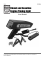
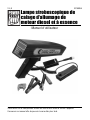
User Manual
Diesel and Gasoline
Engine Timing Light

8706855 Diesel and Gasoline Engine Timing Light V4.0
2 For technical questions call 1-800-665-8685
SPECIFICATIONS
Voltage Rating 12V DC
Speed Rating 10,000 RPM
Adjust Ignition 0 to 60°
Number of Cylinders 4, 6, 8
Operating Temperature 32 to 104°F (0 to 40°C )
Material High impact plastic
ACCURACY
Advance 0 to 60° + 0.7%RDG + 1%RNG
Tachometer 200 to 9,990 RPM + 0.7%RDG + 1%RNG
Dwell 0 to 99.9% + 0.7%RDG + 1%RNG
Volts 0 to 30V + 0.7%RDG + 1%RNG
INTRODUCTION
The Diesel and Gasoline Engine Timing Light allows you to quickly determine
and adjust an engine’s ignition timing.
SAFETY
WARNING! Read and understand all instructions before using this tool. The
operator must follow basic precautions to reduce the risk of personal injury
and/or damage to the equipment.
Keep this manual for safety warnings, precautions, operating or inspection and
maintenance instructions.
Diesel and Gasoline
Engine Timing Light

V4.0 Diesel and Gasoline Engine Timing Light 8706855
Visit www.princessauto.com for more information 3
HAZARD DEFINITIONS
Please familiarize yourself with the hazard notices found in this manual. A notice
is an alert that there is a possibility of property damage, injury or death if certain
instructions are not followed.
DANGER! This notice indicates an immediate and specific hazard that will
result in severe personal injury or death if the proper precautions
are not taken.
WARNING! This notice indicates a specific hazard or unsafe practice that
could result in severe personal injury or death if the proper
precautions are not taken.
CAUTION! This notice indicates a potentially hazardous situation that may result
in minor or moderate injury if proper practices are not taken.
NOTICE! This notice indicates that a specific hazard or unsafe practice will
result in equipment or property damage, but not personal injury.
WORK AREA
1. Operate in a safe work environment. Keep your work area clean, well-lit
and free of distractions.
2. Keep anyone not wearing the appropriate safety equipment away from the
work area.
3. Store unused tools properly in a safe and dry location to prevent rust or
damage. Lock tools away and keep out of the reach of children.
4. Do not install or use in the presence of flammable gases, dust or liquids.
PERSONAL SAFETY
WARNING! Wear personal protective equipment approved by the Canadian
Standards Association (CSA) or American National Standards Institute (ANSI).
PERSONAL PROTECTIVE EQUIPMENT
1. Always wear impact safety goggles that provide front and side protection
for the eyes. Eye protection equipment should comply with CSA Z94.3-07
or ANSI Z87.1 standards based on the type of work performed.

8706855 Diesel and Gasoline Engine Timing Light V4.0
4 For technical questions call 1-800-665-8685
2. Wear gloves that provide protection based on the work materials or to
reduce the effects of tool vibration.
a. Do not wear gloves when operating a tool that can snag the material
and pull the hand into the tool.
3. Wear protective clothing designed for the work environment and tool.
4. Non-skid footwear is recommended to maintain footing and balance in the
work environment.
PERSONAL PRECAUTIONS
Control the tool, personal movement and the work environment to avoid
personal injury or damage to tool.
1. Do not operate any tool when tired or under the influence of drugs, alcohol
or medications.
2. Avoid wearing clothes or jewelry that can become entangled with the
moving parts of a tool. Keep long hair covered or bound.
3. Do not overreach when operating a tool. Proper footing and balance
enables better control in unexpected situations.
SPECIFIC SAFETY PRECAUTIONS
WARNING! DO NOT let comfort or familiarity with product (gained from
repeated use) replace strict adherence to the tool safety rules. If you use
this tool unsafely or incorrectly, you can suffer serious personal injury.
1. Use the correct tool for the job. This tool was designed for a specific
function. Do not modify or alter this tool or use it for an unintended purpose.
2. The inductive clamp must not be snapped closed, dropped or handled
roughly. The ferrite material is fragile and damage may compromise the
engine timing light’s accuracy.
3. Secure the vehicle. Set it in parking gear, engage the parking brake and
chock the wheels.
4. The engine and exhaust become very hot during operation. Severe thermal
burns can occur on contact.
5. DO NOT touch any part of the ignition system while the engine is running.
Dangerous voltages are present throughout the system, including the cable
harness, connectors and the tools leads are connected to the engine or battery.

V4.0 Diesel and Gasoline Engine Timing Light 8706855
Visit www.princessauto.com for more information 5
CARBON MONOXIDE POISONING
DANGER! Never operate a gas engine indoors or in a confined space as the
exhaust contains carbon monoxide gas. Inhalation of carbon monoxide gas
can lead to illness or death. The area must be well ventilated. Opening
windows and doors is not enough to ventilate an area.
Carbon monoxide poisoning results from inhalation of the gas and may be lethal if
left untreated. Evacuate all people to an area with clean air and seek immediate
medical attention for any person experiencing the following symptoms:
• Headache
• Confusion
• Shortness of breath
• Weakness
• Chest pain
• Dizziness
• Vision trouble
• Nausea and vomiting
• Unconsciousness
UNPACKING
WARNING! Do not operate the tool if any part is missing. Replace the
missing part before operating. Failure to do so could result in a malfunction
and personal injury.
Remove the parts and accessories from the packaging and inspect for damage.
Make sure that all items in the Identification Key are included.

8706855 Diesel and Gasoline Engine Timing Light V4.0
6 For technical questions call 1-800-665-8685
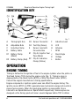
IDENTIFICATION KEY
A Timing Light Gun
B Adjustable Nuts
C Inductive Clamp
D Battery Cable
D1 Battery Clamp
(Black)
D2 Battery Clamp (Red)
D3 Sensor Connector
D4 Test Clip (Green)
E Sensor Lead with
Converter Box
E1 Clip for Injector Fuel
Pipe (Black)
E2 Clip for Inductive
Clamp (Yellow)
F Inductive Lead
G LCD
H Advance
I RPM
J Dwell Angle
K Voltage
L Button
OPERATION
ENGINE TIMING
Timing is defined as the ignition of fuel in the engine cylinder when the piston is
Top Dead Center (TDC) during the engine cycle (Fig. 1). Timing is given in
degrees Before Top Dead Center (BTDC) or After Top Dead Center (ATDC).
Consult the engine manufacturer's timing specifications.
Engine component or ignition system wear can affect the engine timing. The
ignition occurs BTDC or ATDC, generates less mechanical energy and results in
poorer fuel economy. When the spark plug ignition is responsible, this is
referred to as Spark Advance or Spark Retard respectively. Some engines are
designed so the timing spark will occur several degrees before TDC to obtain
Fig. 1

V4.0 Diesel and Gasoline Engine Timing Light 8706855
Visit www.princessauto.com for more information 7
maximum efficiency from the ignition, while some vehicles equipped with
emission control devices will have a retarded ignition to reduce pollution.
Adjusting the ignition distributor will change the engine timing. Timing marks
may be found on the engine vibration damper or the fan pulley at the lower front
part of the engine. Older style engines the mark is found on the flywheel.
WHEN TO CHECK TIMING
Problems with ignition system’s spark plugs or breaker points on an older
engine can cause a timing misfire. This can occur due normal wear on the
components that will eventually require replacement.
Replacing engine components in the ignition system may also require you to
reset the timing. The new component’s setting or configuration out of the box
may be incorrect for your engine.
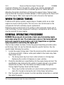
GENERAL OPERATING PROCEDURE
WARNING! Keep any part of your body or tools away from moving engine
parts when using this tool. The stroboscopic nature of the timing light will
make parts appear to move slowly or not at all. Amputation or a grevious
injury may result in contacting the engine part.
The tool has multiple functions. Follow the general operating procedure when
performing a task, but use the alternate steps for specific function. See the
specific tasks following this section.
1. Locate the engine timing mark. Clean the area around the mark and pointer
of all grease and dirt. Chalk or white paint added to the marks may make
them easier to see.
a. The timing mark may be a line in older vehicles or a timing tape
displaying the number of degrees on newer vehicles.
2. Check the manufacturer's specifications for the engine being serviced. The
specifications may be found in the vehicle or engine manual, or on a decal
beneath the car hood. This information normally includes the Ignition
Timing, Spark Plug Gap, Dwell and Idle Speed.
a. There may be other instructions on what vehicle systems should be
shut off or turned on during the test. Follow these instructions.
3. Run the engine until the engine’s normal operating temperature is reached,
then stop the engine.

8706855 Diesel and Gasoline Engine Timing Light V4.0
8 For technical questions call 1-800-665-8685
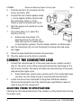
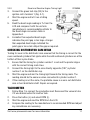
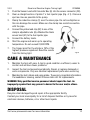
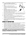
4. Push the lead (E or F) connector into the
sensor connector (D3).
5. Connect the tool’s black negative clamp
(-) to the negative battery terminal and
the red positive clamp (+) to the
battery’s positive terminal (see Fig. 2).
6. Start the engine and operate at normal
idle speed.
7. Press the button (L) to select the
function (H to K).
a. Advance has two options. The
decimal point in the LCD (G) will
flash when set for a 2-stroke engine
or direct-ignition systems. The dot remains solid for a 4-strike engine.
8. Aim the timing light (A) so it will illuminate the timing mark and press
the trigger.
9. Follow the steps listed below based on the procedure.
10. Stop the engine once the task is complete.
CONNECT THE CONDUCTIVE LEAD
1. Connect the inductive lead (F) to the spark plug lead on cylinder number 1
(Fig. 2). The arrow on the clamp must point towards the spark plug for the
tool to work correctly. The clamp will detect the electrical pulse to the spark
plug during the engine cycle.
a. Some distribution system have a positive earth. If the strobe light does
not work, turn the clamp around to point towards the distributor.
2. Locate the vacuum line connected to the ignition distributor advance.
Disconnect and plug the line if the vehicle/engine specifications require it.
Insert a plug into the vacuum port.
ADJUSTING TIMING TO SPECIFICATIONS
Checking the idle timing determines if the cylinder is at Top Dead Center during
the engine cycle.
Fig. 2

V4.0 Diesel and Gasoline Engine Timing Light 8706855
Visit www.princessauto.com for more information 9
1. Connect the conductive lead.
2. The pointer will align with the timing mark or align with the correct degree
number if the idle is set correctly.
3. Advance the timing when the timing mark is above (to the left) of the pointer
or the degree number is less than the manufacturer’s recommendation.
4. Retard the timing when the timing mark is below (to the right) of the pointer or
the degree number is more than the manufacturer’s recommendation.
5. Loosen the bolt located at base of the distributor, but do not remove it. The
bolt must be loose enough to rotate the distributor back and forth by hand,
but not enough that the distributor can rotate by itself.
6. Start the engine.
7. Direct the timing light at the timing marks so the pointer is visible and
stationary. Slowly rotate the distributor right and left until the pointer aligns
with the TDC indicator on the timing marks.
a. Advance the timing by turning the distributor counterclockwise.
b. Retard the timing by turning the distributor clockwise.
8. Tighten the bolt at the distributor’s base without changing the
distributor’s position.
9. Restart engine and recheck the timing is correct.
10. Once the timing is correct, remove the vacuum plug and reinsert the
vacuum hose.
CHECKING VACUUM ADVANCE
1. Connect the conductive lead.
2. Increase the engine speed to 2,000 RPM.
a. A second person or a pedal depressor may be necessary if the choke
lever is difficult or unsafe to manipulate while taking a timing reading.
3. Squeeze the trigger to activate the timing light. Slowly rotate the knob on
the side of the timing light gun (A), stopping when the pointer centers on
TDC or the timing tapes 0 mark.
4. Observe the reading from the LCD (G) and compare with the manufacturer's
specifications. Follow the engine manufacturer’s instructions to adjust the
advance.

8706855 Diesel and Gasoline Engine Timing Light V4.0
10 For technical questions call 1-800-665-8685
TESTING CENTRIFUGAL ADVANCE
The centrifugal advance tests if the distributor’s mechanical mechanism will
cause each piston’s spark plug to fire earlier as the engine’s RPM increases.
1. Connect the conductive lead.
2. Speed the engine up slowly and watch the timing mark.
3. The timing mark should remain stationary until the engine reaches the
manufacturer's specified speed. The timing mark should then move
steadily and without jerking.
4. Reduce the engine speed and the mark should move steadily back.
5. Service the centrifugal (automatic) advance if the mark does not move or if
it moves erratically,
6. To check the maximum advance, it is necessary to mark the harmonic
balancer with the maximum degree per manufacturer's specifications and
follow manufacturer's procedures.
TESTING VACUUM ADVANCE
The vacuum advance tests if the distributor’s vacuum mechanism will
cause each piston’s spark plug to fire earlier as the engine’s RPM increases.
The engine timing light remains connected and the vacuum line must be
properly installed.
1. Follow Step 1 in connect the conductive lead. Reconnect the vacuum tube
if it was disconnected for another task.
2. Set the engine speed fast enough to apply vacuum to the distributor.
3. Aim the timing light and note the position of the pointer.
4. Disconnect the vacuum line and the pointer should move.
5. The distributor should be serviced if the pointer does not move. The trouble
may be a plugged line, a leaky diaphragm or a frozen distributor plate.
DWELL ANGLE MEASUREMENT
1. Follow Step 1 in connect the conductive lead. Reconnect the vacuum tube
if it was disconnected for another task.
2. Press the button (L) to select the dwell angle (J).

V4.0 Diesel and Gasoline Engine Timing Light 8706855
Visit www.princessauto.com for more information 11
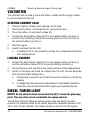
3. Connect the green test clip (D4) to the
ignition coil’s terminal 1 (Fig. 3-1).
4 Start the engine and let it run at idling
speed.
5. Read the dwell angle reading in % from the
LCD and compare it with the verhicle
manufacturer's recommendations.Refer to
the Dwell Angle conversion table in
Appendix A.
6. A smaller than expected dwell angle
indicates the point gap is too large. A larger
than expected dwell angle indicated the
point gap is too small. Adjust the gap as required.
CHECKING DISTRIBUTOR CAM WEAR
Testing for wear in the distributor cam ensures that the timing is correct for the
even numbered cylinders that ignite while the odd numbered cylinders are at the
bottom of their cycle stroke.
1. Ensure that the timing for cylinder number 1 is set and the pointer aligns
with the correct timing mark lines.
2. Connect the timing light to the wire directly opposite (180°) cylinder
number 1 on the distributor cap.
3. Start the engine and aim the timing light towards the timing mark. The
reading should be the same as when connected to cylinder number 1.
4. If the reading is not the same, the probable cause is a worn out distributor
cam or bent distributor shaft. Repair as required.
TACHOMETER
1. Follow Step 1 in connect the conductive lead. Reconnect the vacuum tube
if it was disconnected for another task.
2. Press the button (L) and select RPM (I).
3. Start the engine and read the RPM from the LCD.
4. Compare the reading to the manufacturer’s recommended RPM and adjust
any calculations are necessary.
Fig. 3

8706855 Diesel and Gasoline Engine Timing Light V4.0
12 For technical questions call 1-800-665-8685
VOLTMETER
The voltmeter can be used to check the battery voltage and the supply voltage
to various electronic devices.
STARTING CURRENT LOAD
1. Testing of battery voltage under starting current load.
2. Disconnect terminal 1 on the ignition by removing the wire.
3. Press the button (L) and select voltage (K).
4. Connect the black battery clamp (D1) to the negative battery terminal (-)
and both the red battery clamp (D2) and the green test clip (D4) clips to
the positive battery terminal (+).
5. Start the engine.
6. Read the voltage from the LCD.
a. A reading of 9V or less should be verified by a professional technician
with a separate test.
LOADING CURRENT
1. Connect the black battery clamp (D1) to the negative battery terminal (-)
and the red battery clamp (D2) to the positive battery terminal (+).
2. Connect the green test clip (D4) to the positive terminal of the loading device.
3. Switch on the device and read the voltage from the LCD. Consult Appendix
B for the Admissible Voltage Drop.
a. Voltage leak is possible due to lead connections heating up during the
reading.
b. A voltage drop that exceeds the manufacturer’s specification should be
verified by a service technician before repairing or replacing the part.
DIESEL TIMING LIGHT
NOTICE! Do not allow the black sensor lead clip (E1) to touch the glow plug
plate. This may short-circuit and disable the engine and tool.
The inductive clamp (C) detects a pressure pulse when fuel enters the piston
chamber. The inductive clamp fits on injector pipes with a diameter between 1/4 to
3/8 in. (6 to 10 mm) diameter. The clamp will work on most 12 or 24V engines.

V4.0 Diesel and Gasoline Engine Timing Light 8706855
Visit www.princessauto.com for more information 13
1. Push the Sensor Lead with Converter Box (E) into the sensor connector (D3).
2. Clean a straight section of piston 1’s fuel injector pipe (Fig. 4-1). Choose a
spot as close as possible to the pump.
3. Clamp the inductive clamp (C) over the clean pipe. Do not overtighten as
this can damage the sensor. Make sure the clamp has a solid connection
with the pipe.
4. Connect the yellow lead clip (E2) to one of the
clamp’s adjustable nuts (B). Attached the black
sensor lead (E1) to the fuel injector pipe.
5. Connect the battery leads.
6. Start the engine and warm up to operating
temperature. Do not exceed 2,000 RPM.
7. The trigger point for the strobe is 15% of the
highest pressure registered. Read the results
from the timing light.
CARE & MAINTENANCE
1. Maintain the tool with care. A tool in good condition is efficient, easier to
control and will have fewer problems.
2. Inspect the tool components periodically. Repair or replace damaged or
worn components. Only use identical replacement parts when servicing.
3. Maintain the tool’s labels and name plates. These carry important information.
If unreadable or missing, contact Princess Auto Ltd. for replacements.
WARNING! Only qualified service personnel should repair the tool. An
improperly repaired tool may present a hazard to the user and/or others.
DISPOSAL
Recycle a tool damaged beyond repair at the appropriate facility.
Contact your local municipality for a list of disposal facilities or by-laws for
electronic devices, batteries, oil or other toxic liquids.
Fig. 4

8706855 Diesel and Gasoline Engine Timing Light V4.0
14 For technical questions call 1-800-665-8685
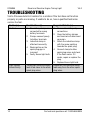
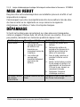
TROUBLESHOOTING
Visit a Princess Auto Ltd. location for a solution if the tool does not function
properly or parts are missing. If unable to do so, have a qualified technician
service the tool.
Problem(s) Possible Cause(s) Suggested Solution(s)
No flash. 1. The battery clamps are
connected to wrong
battery terminals.
2. Clamps connect poorly
to battery terminals.
3. Inductive clamp is
attached incorrectly.
4. Weak ignition or the
spark plug gap is
incorrect.
5. Faulty Xenon light bulb
1. Reverse the battery clip
connections.
2. Clean the battery clamps
and terminals of debris and
corrosion.
3. Attach the inductive clamp
with the arrow pointing
towards the spark plug.
4. Connect clamp to other
spark plug wires and check
if the flash works. If it
works, repair or replace the
plug.
5. Replace Xenon light bulb.
Light flashes
Intermittently.
Timing light inductive clamp
lead is too close to the other
spark plug wires.
Reposition the inductive clamp
lead away from the other spark
plug wires.

V4.0 Diesel and Gasoline Engine Timing Light 8706855
Visit www.princessauto.com for more information 15
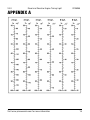
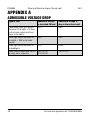
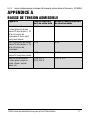
APPENDIX A

8706855 Diesel and Gasoline Engine Timing Light V4.0
16 For technical questions call 1-800-665-8685
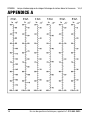
APPENDIX A
ADMISSIBLE VOLTAGE DROP
Type of lead Admissible voltage
in Insulated CU lead
Admissible voltage in
drop in the entire circuit
Lamp leads from light switch
Terminal 30 to lights < 15 W or
to the trailer socket and from
there to the lights
0.1V 0.6V
From light switch terminal 30
to Lights < 15W or to trailer
socket
0.5V 0.9V
From light switch terminal 30
to headlights
0.3V 0.06V
From control leads from switch
to relay, horn, wiper etc.
0.5V to 12V
2.0V to 24V
1.5V to 12V

V4.0 Diesel and Gasoline Engine Timing Light 8706855
Visit www.princessauto.com for more information 17

8706855 Diesel and Gasoline Engine Timing Light V4.0
18 For technical questions call 1-800-665-8685

V 4,0 8706855
Vous devez lire et comprendre toutes les instructions avant d'utiliser l'appareil.
Conservez ce manuel afin de pouvoir le consulter plus tard.
Manuel d'utilisateur
Lampe stroboscopique de
calage d'allumage de
moteur diesel et à essence

8706855 Lampe stroboscopique de calage d'allumage de moteur diesel et à essence V 4,0
2 En cas de questions techniques, appelez le 1-800-665-8685
SPÉCIFICATIONS
Tension nominale 12 V c.c.
Vitesse nominale 10 000 tr/min
Régler l’allumage 0 à 60 °
Nombre de cylindres 4, 6, 8
Température de fonctionnement 0 à 40 °C (32 à 104 °F)
Matériau Plastique résistant aux chocs
PRÉCISION
Avance à l'allumage 0 à 60 ° + 0.7%RDG + 1%RNG
Tachymètre 200 à 9 990 tr/min + 0.7%RDG + 1%RNG
Dwell 0 à 99,9 % + 0.7%RDG + 1%RNG
Volt 0 à 30 V c.c. + 0.7%RDG + 1%RNG
INTRODUCTION
La lampe stroboscopique de calage d'allumage de moteur diesel et à essence
pour moteur vous permet de déterminer et d’ajuster rapidement le calage de
l’allumage du moteur.
SÉCURITÉ
AVERTISSEMENT ! Veuillez lire et comprendre toutes les instructions avant
d'utiliser cet outil. L'utilisateur doit respecter les précautions de base
lorsqu'il utilise cet outil afin de réduire le risque de blessure ou de
dommage à l'équipement.
Conservez ce manuel qui contient les avertissements de sécurité, les
précautions, les instructions de fonctionnement ou d'inspection et d'entretien.
Lampe stroboscopique de
calage d'allumage de
moteur diesel et à essence
La page est en cours de chargement...
La page est en cours de chargement...
La page est en cours de chargement...
La page est en cours de chargement...
La page est en cours de chargement...
La page est en cours de chargement...
La page est en cours de chargement...
La page est en cours de chargement...
La page est en cours de chargement...
La page est en cours de chargement...
La page est en cours de chargement...
La page est en cours de chargement...
La page est en cours de chargement...
La page est en cours de chargement...
La page est en cours de chargement...
La page est en cours de chargement...
-
 1
1
-
 2
2
-
 3
3
-
 4
4
-
 5
5
-
 6
6
-
 7
7
-
 8
8
-
 9
9
-
 10
10
-
 11
11
-
 12
12
-
 13
13
-
 14
14
-
 15
15
-
 16
16
-
 17
17
-
 18
18
-
 19
19
-
 20
20
-
 21
21
-
 22
22
-
 23
23
-
 24
24
-
 25
25
-
 26
26
-
 27
27
-
 28
28
-
 29
29
-
 30
30
-
 31
31
-
 32
32
-
 33
33
-
 34
34
-
 35
35
-
 36
36


Power Fist 8706855 Le manuel du propriétaire
- Taper
- Le manuel du propriétaire
dans d''autres langues
- English: Power Fist 8706855 Owner's manual
Documents connexes
-
Power Fist 8709529 Le manuel du propriétaire
-
-
-
-
-
-
-
-
-
Autres documents
-
Innova 3568a Le manuel du propriétaire
-
-
Innova 3551a Le manuel du propriétaire
-
Facom X.730B Le manuel du propriétaire
-
Actron CP7529 Manuel utilisateur
-
Powerfist 8659005 Le manuel du propriétaire
-
-
-
-