La page est en cours de chargement...

SWING TYPE AIR/ELECTRIC TIRE CHANGER
EEWH329A
OPERATION INSTRUCTIONS
Air-Electric tilt back tower tire changers for car, light commercial vehicle and motor-
cycle tires designed for one-piece rims. Dimensions based on OEM tires and wheels
only. This tire changer is designed for ease of operation, safe handling of rims, relia-
bility and speed.

ii
Snap-On EEWB329A
UPDATING GUIDE :
Release A January 2017
-
First publication -
Release B March 2018
- Accessories Chart updating -
Release B1 February 2019
- Max. wheel diameter capacity: 42” (Page 8).
Release C October 2019
-
Tool adjustment section: replaced picture 4.1-4
. PCN: 19G0142

3
Snap-On EEWH329A
SAFETY INFORMATION
For your safety, read this manual thoroughly
before operating the EEWH329A Tire Changers
The
EEWH329A Tire Changers are intended for use by properly trained
automotive technicians. The safety messages presented in this section and
throughout the manual are reminders to the operator to exercise extreme care
when changing tires with these products.
There are many variations in procedures, techniques, tools, and parts for
changing tires, as well as the skill of the individual doing the work. Because
of the vast number of wheel and tire applications and potential uses of the
product, the manufacturer cannot possibly anticipate or provide advice or
safety messages to cover every situation. It is the automotive technician’s
responsibility to be knowledgeable of the wheels and tires being changed. It
is essential to use proper service methods and change tires in an appropriate
and acceptable manner that does not endanger your safety, the safety of others
in the work area or the equipment or vehicle being serviced.
It is assumed that, prior to using the EEWH329A Tire Changers, the operator has
a thorough understanding of the wheels and tires being changed. In addition, it
is assumed he has a thorough knowledge of the operation and safety features
of the rack, lift, or fl oor jack being utilized, and has the proper hand and power
tools necessary to service the vehicle in a safe manner.
Before using the EEWH329A Tire Changers, always refer to and follow the
safety messages and service procedures provided by the manufacturers of
the equipment being used and the vehicle being serviced.
IMPORTANT !! SAVE THESE INSTRUCTIONS - DO NOT DISCARD !!

4
Snap-On EEWH329A
Overinfl ated tires or tires mounted on the wrong sized rims can explode producing
hazardous fl ying debris.
• Read Operator’s Manual before using this Tire Changer.
• Never mount tire on rim with different sized diameter.
• Never exceed maximum infl ation pressure listed on tire sidewall.
• Always use safety restraint arm to hold wheel in place while
infl ating.
• Always use attached air hose to infl ate tires.
Exploding tires can cause death or serious injury.
Risk of electrical shock.
• Do not operate equipment with a damaged power cord or if the
equipment has been dropped or damaged, until it has been
examined by a qualifi ed service person.
• If an extension cord is necessary, a cord with a current rating equal
to or greater than that of the equipment should be used. Cords
rated for less current than the equipment can overheat.
• Unplug equipment from electrical outlet when not in use. Never
use the cord to pull the plug from the outlet. Grasp plug and pull to
disconnect.
• Do not expose the equipment to rain. Do not use on wet surfaces.
• Plug unit into correct power supply.
• Do not remove or bypass grounding pin.
Contact with high voltages can cause death or serious injury.
Risk of electrical shock. High voltages are present within the base unit.
• There are no user serviceable items within the unit.
• Service on the unit must be performed by qualifi ed personnel.
• Do not open any part of the base cabinet.
• Unplug the unit before servicing.
Contact with high voltages can cause death or serious injury.
Risk of crushing. Stand clear of bead breaker arm during operation.
• Read and understand the operation instructions before using this tire changer.
• Become familiar with all controls before proceeding with operation.
• Stand away from the bead breaker arm when in operation.
• Apply air to breaker in bursts if necessary to control arm depth.
• Keep all persons clear of tire changer.
Contact with moving parts could cause injury.
SAFETY INSTRUCTIONS
IMPORTANT!! SAVE THESE INSTRUCTIONS!!

5
Snap-On EEWH329A
Risk of pinching or crushing hands and fi ngers when mounting and demounting.
• Read and understand the operation instructions before using this tire changer.
• Keep hands and fi ngers clear of rim edge during demounting and mounting
process.
• Keep hands and fi ngers clear of mount/demount head during opera tion.
• Keep hands and other body parts away from moving surfaces.
• Do not use tools other than those supplied with tire changer.
• Do not bypass any safety features.
• Use proper tire lubricant to prevent tire binding.
Contact with moving parts could cause injury.
Risk of eye injury. Flying debris, dirt, and fl uids may be discharged during bead
seating and infl ation process.
• Remove any debris from tire tread and wheel surfaces.
• Remove excess tire lubricant before infl ating.
• Wear approved safety glasses during mount and demount
procedures.
Debris, dirt, and fl uids can cause serious eye injury.
Risk of injury. Tools may break or slip if improperly used or maintained.
• Read and understand the operation instructions before using this tire changer.
• Use only the mount/demount tire tool supplied with the tire changer.
• Frequently inspect, clean, and lubricate (if recommended) where designated.
• Follow procedures when instructed in this manual.
Tools that break or slip can cause injury.
Collision and dragging hazard:
• Do not rotate the turntable without a wheel.
• Do not approach the fl ange if it is moving.
• Pay attention to the claws when they project from the fl ange.
• Do not place projecting objects on the fl ange.
• Do not place projecting objects close to the fl ange.
Contact with moving parts can cause injuries.
IMPORTANT !! SAVE THESE INSTRUCTIONS — DO NOT DISCARD !!

6
Snap-On EEWH329A
Tires and rims that are not the same diameter are mismatched.
• NEVER attempt to mount or infl ate any tire and rim that are mismatched.
• ALWAYS check to see that tire and rim diameters are the same.
A mismatched tire and rim could explode causing death or serious personal injury.
Over-pressurized tires can explode causing fl ying debris.
• Read and understand Operator’s Manual before operating.
• Keep bystanders away from work area.
• ALWAYS wear Safety Goggles.
• ALWAYS check to see that tire and rim diameters are the same.
• NEVER attempt to mount or infl ate any tire and rim with different diameters.
• Inspect tires. NEVER infl ate tires that are damaged, rotten or worn.
• NEVER infl ate ‘Split Rim Wheels’ on this tire changer or remove them and use only
an approved safety infl ation cage designed for this purpose.
• Lock turntable clamp on inside of rim before attempting to infl ate tire.
• Use approved tire bead lubricant before removing or installing tire on rim.
• ALWAYS position the “Safety Restraint Arm” over the wheel to hold it to the
turntable while infl ating if so equipped.
• If a tire explodes on this tire changer, STOP using it until the “Safety Restraint
Arm” has been replaced, which must be done even if no damage is seen.
• NEVER place head or body over a tire during infl ation process.
• Use short bursts of air to seat tire beads. Check tire air pressure
frequently. NEVER exceed tire manufacturer’s pressure limits.
• NEVER attempt to bypass or alter the built-in air pressure limiter. Only infl ate tire
with air hose supplied with tire changer. NEVER use shop infl ation hose to infl ate a
tire.
• Tire Changer must be anchored to concrete fl oor if equipped with a “Safety
Restraint Arm”.
Exploding tires can cause serious injury.

7
Snap-On EEWH329A
Table of contents
SAFETY .................................................................................................................Page 3
TABLE OF CONTENTS
......................................................................................... Page 7
1.0 INTRODUCTION ........................................................................................... Page 8
1.1 SPECIFICATIONS ......................................................................................... Page 8
1.1.1 FEATURES .................................................................................................. Page 9
1.2 MACHINE DIMENSIONS .............................................................................. Page 10
1.3 NOMENCLATURE......................................................................................... Page 10
1.4 ACCESSORIES ............................................................................................ Page 11
1.5 GENERAL CAUTIONS .................................................................................. Page 12
2.0 INSTALLATION ............................................................................................. Page 12
2.1 ELECTRIC INSTALLATION ........................................................................... Page 12
2.2 BEAD BREAKER INSTALLATION ................................................................ Page 12
2.3 AIR INSTALLATION ...................................................................................... Page 13
3.0 CONTROLS .................................................................................................. Page 13
3.1 PRESETTING OF CLAMPING JAWS ........................................................... Page 14
4.0 MOUNTING AND DEMOUNTING PRECAUTIONS ...................................... Page 15
4.1 DEMOUNTING TUBELESS TIRES ............................................................... Page 15
4.2 MOUNTING TUBELESS TIRES .................................................................... Page 17
4.3 IF THE TOP TIRE BEAD IS DIFFICULT TO MOUNT ...................................Page 18
4.4 INFLATION OF TUBELESS TIRES ............................................................... Page 19
5.0 DEMOUNTING TUBE TYPE TIRES ............................................................. Page 20
5.1 MOUNTING TUBE TYPE TIRES .................................................................. Page 20
5.2 INFLATING TUBE TYPE TIRES ...................................................................Page 21
5.3 OPERATING THE PNEUMATIC BEAD ASSIST ........................................... Page 21
5.4 MOUNTING AND DEMOUNTING MOTORCYCLE TIRES ........................... Page 22
6.0 MAINTENANCE ............................................................................................ Page 23
7.0 DISPOSING OF THE UNIT ...........................................................................Page 24
7.1 INSTRUCTIONS FOR DISPOSAL
................................................................ Page 24
WARRANTY .................................................................................................. Page 26
--------------------------- EN ---------------------------

8
Snap-On EEWH329A
1.0 INTRODUCTION
Congratulations on your purchase of the Snap-on
EEWH
329A air-electric tire changer. This tire changer
is designed for ease of operation, safe handling of rims,
reliability and speed. This combination of features
means more profi t and added versatility for your shop,
enabling you to work with aluminum or magnesium
alloy wheels with reduced risk of damage. With a
minimum of maintenance and care your Snap-on
EEWH329A Tire Changer will provide many years of
trouble-free operation.
Please read this manual thoroughly before operating
the unit. Instructions on use, maintenance and
operational requirements of the machine are covered
in this manual.
STORE THIS MANUAL IN A SAFE PLACE FOR
FUTURE REFERENCE
1.1 SPECIFICATIONS
Operation temperature range: +41/+122 F (+5/50 C)
A
ir-
Electric tire changers for car, light commercial
vehicle and motorcycle tires designed for one-piece
rims.
EEWH329A
• Outside clamping rim diameter capacity: 10” to 24”
• Inside clamping rim diameter capacity: 12” to 26”
• Rim Width Maximum: 14”
• Tire Diameter Maximum: 42”
• Bead Breaking Force: 3300 lbs. at 150 psi air supply
• Electric Requirements: 110V, 60Hz, 20 amp
• Shipping Weight: 620 pounds

9
Snap-On EEWH329A
1.1.1 TURNTABLE & CABINET FEATURES
EEWH329A
INTEGRATED BEAD SEATING JETS - Air infl
ation jets
are integrated into the turntable clamping jaws to insure full
bead seating force directly into the tire cavity regardless
of tire diameter.
ADJUSTABLE BEAD BREAKER OPENING - Simple two-
position bead breaker pin adjustment allows for readjusting
breaker to fi t larger OD tires.
TWIN CYLINDER CLAMPING POWER - Two 3” clamping
cylinders provide uniform clamping pressure throughout
the stroke (regardless of rim sizes) as well as providing
25% more clamping power than most single clamping
cylinder tire changers. Additionally these two smaller
cylinders reduce the critical turntable to cabinet distance,
reducing the stress on the transmission.
WHEEL CLAMPS
UNIQUE SIX POINTS CONTACT CLAMPS
Provide better gripping capability
regardless from dirt and
moisture.
REDUCED ANGLE CLAMPS
Increases clamping contact area with rim insuring no
slippage.
NYLON INSERT SOFT TOUCH CLAMPS
Single sided nylon insert in the clamping jaws provides
Nonmetal touch in critical customer visible areas.
VALVE CORE/TIRE TOOL STORAGE CABINET
On tire changer storage area for valves, tools, caulk, etc.
INCOMING AIR PRESSURE GAUGE
Ergonomically located air gauge allows easy operator
monitoring of incoming air pressure.
INTEGRATED PRESSURE LIMITER
Integrated safety pressure limiter stops air fl ow once tire
pressure has reached approximately. 55 PSI preventing
accidental tire over-infl ation.
MOUNT/DEMOUNT ARM ASSEMBLY
SURGE TANK IN THE TOWER - Space-saving design
integrates
the air storage surge tank in the tower allowing
for fl ush to wall tire changer installation.
ADJUSTABLE SLIDEWAY - Unique adjustable vertical
mount/demount hex shaft slideway allows for easy
operator adjustment to compensate for any cumulative
wear in the slideway causing mount/demount head
movement.
NON-SCRATCH NYLON INSERT - Integrated into the
mount/demount head is a replaceable scratch resistent
nylon insert protecting against accidental rim contact.
SAFETY RESTRAINT ARM (Optional)
TIRE/RIM ASSEMBLY RESTRAINT - S
afety Restraint Arm
restrains tire and rim assembly to the tire machine during
the infl ation process reducing potential for injury caused
by the unlikely event of catastrophic tire or rim failure.
SIMPLE SWING ARM DESIGN - SRA arm easily swings
to the left when not in use allowing the technician to quickly
and safely perform the infl ation process without disrupting
the tire changing procedure.
GRAVITY LOCK - SRA lock mechanism operates without
any mechanical cam system eliminating the possibility of
system deterioration or mis-adjustment from mechanical
wear.
POSITIONING SAFETY INTERLOCK SWITCH -
Integrated switch insures that SRA arm is centered on the
tire/rim assembly before the infl ation process can begin.
ANTI-ROTATION LOCK - Prevents SRA from rotating
horizontally during infl ation process.
CONSTRUCTION DESIGNED FOR DURABILITY
RUST PROOF VALVES AND CYLINDERS - Cr
itical bead
breaking cylinder is lined with rustproof polyfi ber liner for
years of rust free operation. Non-lined cylinders will pit
causing bead breaker power loss.
LIFETIME LUBRICATED POLYMER VALVES - Critical
footvalves fabricated from glass/fiber self-lubricating
material providing years of maintenance free operation.
WATER SEPARATOR AND AUTOMATIC OILER -
Lubricates all air used for machine operation, does not
lubricate air used for tire infl ation, as do some competitive
models.
HIGH TORQUE 1HP MOTOR - (air-electric models)
Industrial strength high torque turntable drive motor
eliminates tire remount stalling on low profile high
performance tires (UL/CSA approved ).
3-YEAR TRANSMISSION WARRANTY - Designed
for extremely heavy use, the critical motor to turntable
transmission linkage carries a full three (3) years
replacement warranty.

10
Snap-On EEWH329A
PNEUMATIC BEAD ASSIST ARM
Up/Down Control Switch - Toggle
switch allows single
fi nger operation of all pneumatic PBA functions, with or
without gloves.
Top Bead Roller - Provides easily controlled pneumatic
power to drive upper beads down into the wheel drop
center (while tire is turning) for easy lubrication prior to
dismounting. Also provides pneumatic power assistance
for safely remounting second bead on extremely low profi le
and Run Flat design tires.
Bead Depressor - Provides easily controlled pneumatic
power to depress the tires sidewall during the remount
cycle. This will prevent premature bead seating before the
entire bead has been reinstalled on the wheel. Provides
an added level of safety by keeping the technicians hands
away from the bead area during this potential pinch point
procedure. Additionally the Bead Depressor “follows” the
tire around while turning to guarantee successful remount
fi rst time everytime.
Bottom Bead Roller - Provides easily controlled
pneumatic power to unseat stubborn lower beads which
may have accidentally reseated after the original bead
breaking procedure. Also allows a technician to raise and
hold wider tires up, to assist in safely and easily getting the
second bead up onto the mount/demount head.
Wheel Centering Depressor - Provides downward
pressure on a rim when working to clamp a low profi le
tire/rim combination. Will assist the technician in correctly
seating the rim clamps between the tire and the rim when
clamping from outside in where it is diffi cult to depress the
tire sidewall enough to expose the rim edge.
1.3 NOMENCLATURE
Before installing and using the Snap-on EEWH329A
T
ire Changer it is suggested that you become familiar
with the nomenclature of the machine’s components.
Figure 1.2-1
1 Vertical Hex Shaft
2 Swing Arm
3 Rim Diameter Adjustment
4 Mount/Demount Head Lock lever
5 Mount/Demount Head
6 Tower or Column
7 Turntable
8 Clamping Jaws
8a Infl ation Jets
9 Rim Clamps
10 Bead breaker arm
11 Bead breaker blade
12 Bead breaker pads
13 Foot pedal controls
14 Bead seater/infl ator pedal
15 Infl ation gauge
16 Tire tool lever
17
Tool grip Quick Exchange
18 T
ools storage areas
19 Stop button
PNEUMATIC BEAD ASSIST DEVICE (PBA)
20 Tower Raise/Lower Control Lever
21 Top Bead Roller
22 Bead Assist Arm
23 Lower Bead Assist Roller
24 Movable Tower
25 Top Bead Depressor
26 Depressor Shoe
1.2 MACHINE DIMENSIONS
Figure 1.3-1
Dimensions W=
48” x D=67” x H=73” 1/4

11
Snap-On EEWH329A
1.4 ACCESSORIES AND CONSUMABLES
! "
#$% "
!
& !"#$%&%
% % '"%()%%*+*,-*%
$./ ! "011$./
$./ 2%
$./ & 3$./ "
$./ '!&(( 4.5
$./ ! & #/
$./ ! $. / "
$./ ! 3$./
$./ #%& ! $. "
$./ )! & 331)%6*+7,-% "
$./ % 5 "
44 ! %! #444
44 ! & 443)8
44 ! & 011 5444
44 ! %& 144
44 ! 3 #44
! 4 "
! ! 431)%%*!9,*!%
! : "
%& ( :31)%%**;9,9%
! 3
)8<%# 55
)8<%# 4
)8<%# & & 4/
)8<%# ! 5
)8<%# ! & +5
)8<%# ! &% 54
)8<%# % 31#5%
$=
ϰϴϭ'ϯϬ 1/%=#
"
$= &*%!%( 4 "
$= * 4 "

12
Snap-On EEWH329A
1.5 GENERAL CAUTIONS
A. DURING THE USE AND MAINTENANCE OF THE
MACHINE IT IS MANDA
TORY TO COMPLY WITH
ALL LAWS AND REGULATIONS FOR ACCIDENT
PREVENTION.
B. THE ELECTRICAL POWER SOURCE MUST HAVE
A GROUND CABLE AND THE GROUND CABLE OF
THE MACHINE MUST BE CONNECTED TO THE
GROUND CABLE OF THE POWER SOURCE.
C. BEFORE ANY MAINTENANCE OR REPAIRS
ARE ACCOMPLISHED THE MACHINE MUST BE
DISCONNECTED FROM THE AIR AND ELECTRICAL
SUPPLY.
D. NEVER WEAR TIES, CHAINS OR OTHER
LOOSE ARTICLES WHEN USING, MAINTAINING
OR REPAIRING THE MACHINE. LONG HAIR IS
ALSO DANGEROUS AND SHOULD BE KEPT
UNDER A HAT. THE USER MUST WEAR PROPER
SAFETY ATTIRE - GLOVES, SAFETY SHOES AND
GLASSES.
2.0 INSTALLATION
Your new Snap-on EEWH329A T
ire
Changer requires
a simple installation procedure requiring only a few
moments.
Follow these instructions carefully to insure proper
and safe operation.
The Tire Changer is delivered mounted to a wooden
skid. Remove tire changer from its mounts carefully,
taking care to avoid any back strain.
Place Changer where proper operation will be
unobstructed to all sides. Install the machine in a
covered and dry place.
Once placed in the desired location the tire changer
must be bolted to the fl oor using only the rear two
mounting holes. Mounting anchors are provided with
machines.
TIRE CHANGER MUST BE ANCHORED TO
CONCRETE FLOOR.
2.1 ELECTRICAL INSTALLATION
BUILDING ELECTRICAL INSTALLATION MUST BE
MADE BY A LICENSED ELECTRICIAN.
Check that the electrical specifi cations of the power
source are the same as the machine. The machine
uses 110v, 60 hz, grounded single phase 20 amp
source. Electric specifi cations are clearly marked on
a label at the rear of the machine.
FAILURE TO PROVIDE PROPER ELECTRICAL
SUPPLY AND GROUNDING WILL CREATE A
SHOCK HAZARD TO THE OPERATOR.
540
2.2 BEAD BREAKER INSTALLATION
The side mounted Bead Breaker could be shipped from
the factory dismounted for a more compact shipping
package.
A. Cut the plastic tie strap, which secures the Breaker
Arm to the cabinet pivot.
B. Remove the self locking ring nut from the top of the
pivot pin, slip the pin out of the hole.
C. Place the Breaker Arm into position and insert the
pivot pin through the holes from the top.
D. Replace the “C” clip retainer onto the pivot pin.
E. Locate the spring located at the rear of the pivot
mount. Place the free end of the spring onto the “ear”
located on the Breaker Arm just forward of the pivot.
HINT: You may tie a small rope or cord onto the free
end of the spring then run the cord through the hole.
Pull the spring end toward the ear and loop free end
over the ear tab.

13
Snap-On EEWH329A
3.0 CONTROLS
889
Figure 3.0-1
Before operating the machine, take the time to
familiarize yourself with the operation and function of
all the controls.
A Press down and release the fi rst pedal from the left:
the jaws of the turntable will retract. Do it again:
the jaws will expand. If you press the pedal prior
to the end of the stroke and release, the jaws may
be stopped in any position.
B Open the bead breaker arm. Press down and hold
the middle pedal: by doing this you operate the
bead breaker blade and the arm will move towards
the machine. Release the pedal: the bead breaker
blade will retract.
WARNING!
ALWAYS KEEP ARMS AND LEGS AWAY FROM THE
BEAD BREAKER STROKE!!
C Press down the right pedal: the turntable turns
clockwise. Placing your foot under the pedal and
lift, the turntable turns counterclockwise.
D Lower the Lock Lever (3) to unlock the vertical
slide; lift the Lock Lever to lock.
2.3 AIR INSTALLATION
THE AIR INSTALLATION MUST BE MADE ONLY BY
QUALIFIED PERSONNEL.
EXCESSIVE AIR PRESSURE CAN SERIOUSLY
INJURE PERSONNEL AND DAMAGE THE MACHINE.
Ensure that the line pressure is within the limits
required by the machine. If the pressure exceeds
170 psi (12 bar) it is mandatory to install a pressure
regulator before the air inlet of the machine.
If the air pressure is lower than the minimum required of
110 psi (8 bar) the clamping power of the turntable and
the bead breaker power may be insuffi cient for certain
tires and substantially reduces tire changer performance.
It is suggested that the shop air supply be equipped
with a water separator/dryer type modifi cation for
maximum performance.
After ensuring all the above proceed as follows:
A. Connect the machine to the air supply with a rubber
hose (rated for the pressure) with an internal diameter
of no less than 1/2” (12.5mm).
WARNING! BEFORE CONNECTING THE MACHINE
TO THE AIR SUPPLY BE SURE ALL PERSONNEL
ARE CLEAR OF THE MACHINE AND NO ITEMS
ARE LEFT ON THE TURNTABLE.
B.
It is strongly recommended that an air valve shut-off be
installed between the shop air supply and the tire changer
for routine maintenance and in case of an emergency.
C. Should you install any optional accessories, please
refer to the relevant instructions.
D.
Ensure the functional ability of the air lubricator by
ensuring that the glass sight bowl is fi lled with air lubricant.

14
Snap-On EEWH329A
3.1 PRESETTING OF CLAMPING JAWS
MAKE SURE ALL FOUR CLAMPING JAWS ARE
POSITIONED IDENTICALLY (FIG. 3.1-1, ITEMS
1 OR 2). OTHERWISE THE RIM MIGHT NOT BE
CLAMPED PROPERLY, COME OFF THE CHUCK
AND HURT THE OPERATOR!
A
Depress fi rst pedal from the left smoothly up to the
centre position. If the pedal is released the clamping
jaws stop in the position they have reached at the time.
B Set the clamping diameter according to the
dimensions of the rim.
Rim diameters are shown in inches on the turntable
(A, Fig. 3.1-1). The setting diameter (scale on the jaw
-B- corresponding to the scale on the turntable -A-)
depends on the position of the jaws (1, or 2, Fig. 3.1-1).
1115
Fig. 3.1-1
C
To reposition the jaws free the lock pin by applying
pressure on the lever (C) on the right side of each
jaw. Slide the jaws towards the required position and
release the lever: make sure the jaw is now locked
fi rmly. Repeat the procedure on all the turntable jaws.
With the jaws in position 1 (1, Fig. 3.1-1), the operative
diameter is exactly as indicated by the scale (A-B) on
the turntable.
With the jaws in position 2 (2, Fig. 3.1-1), add 4” to the
value represented by the scales to obtain the effective
setting diameter.
D Position wheel and press it down by hand on the
turntable.
E Depress pedal through the fi rst position and release.
The wheel is clamped.
E Turn Swing Arm Adjustment Knob (4) for
positioning mount/demount head slightly away
from rim diameter.
F Lift upward on the restraint-positioning knob (2) to
position over tire/wheel assembly for infl ation, at
the same time push down on the Anti-rotation Lock
Arm to release lock. (1) You may now swing the
safety restraint arm to position on the center of the
wheel. Lower the restraint until the rubber pad on
the restraint disc is resting on the rim center. The
SRA is a gravity lock that will automatically lock if
any force other than the restraint position knob is
lifted. You are now ready for the infl ation process.
NOTE: the turntable infl ation will not function until the
safety arm is centered over the turntable.
G Press bead-seater pedal on left side of the machine
(5, Fig. 3.0-1 / 1, Fig. 3.0-2) halfway down: This
will allow activate the tire infl ation line.
Figure 3.0-2
H Press bead-seater pedal (1, Fig. 3.0-2) swiftly all
the way down to get air blast from the infl ator jets
in the clamping jaws. Air simultaneously comes
out of infl ator hose.
WARNING!!
WHEN OPERATING THE BEAD SEATER IT IS
MANDATORY TO WEAR SAFETY GLASSES TO
PROTECT EYES.

15
Snap-On EEWH329A
4.1 DEMOUNTING TUBELESS TIRES
A. Remove all wheel-weights from the rim. Remove
the valve stem
or valve stem core and defl ate the tire
(Fig. 4.1-1).
535a
Fig. 4.1-1
B. Break both beads.
Hold open the Bead Breaker, roll the tire/rim into the
Breaker area (Fig. 4.1-2). Ensure that the tire/rim
assembly is fl at against the rubber breaker pads on the
side of the machine. Make certain that the bead breaker
blade is not over the top of any portion of the rim. Now
activate the bead breaker pedal. As soon as the bead
dislodges from the rim, release the breaker foot pedal.
It may be necessary to rotate the tire 90 degrees and
repeat the above procedure to dislodge all beads.
Pay extra attention during this operation, as it is easy to
mistakenly keep your foot on the bead-breaking pedal
too long. This could potentially result in bead or rim
damage (Fig. 4.1-2)
536
Fig. 4.1-2
NOTICE !
ON RUN FLAT TIRES WITH THE OPTIONAL LOW
PRESSURE SENSOR INSTALLED, BREAK THE
BEAD AT 90 DEGREES OFFSET FROM THE VALVE
STEM. DAMAGE TO THE WHEEL AND/OR SENSOR
MAY RESULT IF THE BEAD IS BROKEN AT ANY
OTHER POINT ON THE RIM.
4 . 0 M O U N T I N G A N D
DEMOUNTING PRECAUTIONS
IMPORTANT! BEFORE MOUNTING A TIRE ON A
RIM, PAY ATTENTION TO THE FOLLOWING:
A. THE RIM MUST BE CLEAN AND IN GOOD
CONDITION: IF NECESSARY CLEAN IT AFTER
REMOVING ALL WHEEL-WEIGHTS INCLUDING
‘TAPE WEIGHTS’ INSIDE THE RIM.
B. THE TIRE MUST BE CLEAN AND DRY, WITHOUT
ANY DAMAGE TO THE BEAD.
C. REPLACE THE RUBBER VALVE STEM WITH
A NEW ONE OR REPLACE THE ‘O’ RING IF THE
VALVE STEM IS MADE OF METAL.
D. IF THE TIRE REQUIRES A TUBE, MAKE SURE
THE TUBE IS DRY AND IN GOOD CONDITION.
E. LUBRICATION IS NECESSARY TO MOUNT
THE TIRE CORRECTLY AND GET A PROPER
CENTERING. BE SURE YOU ARE USING APPROVED
LUBRICANT ONLY.
F. MAKE SURE THE TIRE IS THE CORRECT SIZE
FOR THE RIM.

16
Snap-On EEWH329A
Angular tool adjustment (Fig. 4.1-4a)
The tool is adjusted at the factory with an optimal an-
gle for most wheels used today. However, the angle
can be optimised for wheels with a diameter that
differs considerably from the standard.
T
o adjust the tool angle, proceed as follows:
1 Mount the rim for which the adjustment is required.
2 Loosen the lower screw (1).
3 Adjust the tool with the screws shown (2a and
2b). Unscrew the screw 2a or 2b to rotate the tool,
respectively clockwise or counterclockwise.
4 Screw in the opposite screw to block the tool in the
desired angular position.
5 Tighten the lower screw (1) with a torque of 35 Nm.
Ø 17"
1/25" (1 mm)
2/3" (17 mm)
Ø 20"
Fig. 4.1-4a
NOTE:
YOUR MACHINE IS SHIPPED WITH SEVERAL
REPLACEMENT PLASTIC INSERTS (INSIDE STANDARD
EQUIPMENT PACK). THE PLASTIC INSERTS WILL
HELP AVOID DAMAGE FROM ACCIDENTAL CONTACT
BETWEEN THE MOUNT/DEMOUNT HEAD AND THE
RIM. THE PLASTIC INSERTS WILL NEED TO BE
PERIODICALLY REPLACED.
MAINTENANCE NOTE:
IF THE MOUNT/DEMOUNT HEAD NYLON INSERTS
ARE WEARING OUT PREMATURELY, THE CAUSE
IS THE OPERATOR’S FAILURE TO CORRECTLY
SET THE RIM DIAMETER ADJUSTMENT KNOB,
CAUSING THE INSERT TO INCORRECTLY
CONTACT THE RIM.
NOTE: ONCE THE MOUNT/DEMOUNT HEAD IS
POSITIONED PROPERLY, IDENTICAL WHEELS
MAY BE CHANGED WITHOUT HAVING TO RESET
THE HEAD.
F. Insert the mount/demount tool between the bead
and the mount/demount head. Pry the bead onto the
mount/demount head using the mount/demount head
C. Set the rim clamps to the proper position: retract
clamps to clamp the wheel from the outside and expand
clamps to clamp from the inside.
When clamping small wheels (14” or smaller) from
the outside, set the clamps at a diameter nearly equal
to the rim diameter before placing the wheel on the
clamps. This will help avoid the possibility of pinching
the tire as the clamps retract.
NOTICE !
TO MINIMIZE THE RISK OF SCRATCHING ALLOY
OR CLEAR COATED RIMS, THESE RIMS SHOULD
BE CLAMPED FROM THE OUTSIDE.ô:
D. Liberally lubricate both beads. Place the wheel
WITH DROP CENTER UP (Fig. 4.1-3a) on the
turntable, and clamp in position. It may be necessary to
hold the tire and wheel down while clamping to insure
contact between rim and clamp as shown in 4.1-3a.
331
Fig. 4.1-3 Fig. 4.1-3a
E. Gently position the mount/demount head in contact
with rim edge, now manually push the lock lever up
and lock it into place. The mount/demount head
automatically moves vertically up and away from
the rim edge. Turn the swing arm adjustment knob
clockwise until the mount/demount head moves
horizontally away from the rim fl ange by approximately
1/16” (2mm): this is necessary to avoid any rim contact
during the changing process. (Fig. 4.1-4).
332a
Fig. 4.1-4

17
Snap-On EEWH329A
4.2 MOUNTING TUBELESS TIRES
A. Clean entire rim surface (Fig. 4.2-1).
336
Fig. 4.2-1
Liberally lubricate both beads of the tire with approved
tire lubricant (Fig. 4.2-2).
337
Fig. 4.2-2
NOTICE!
THESE LUBRICATION OPERATIONS ARE
NECESSARY TO MOUNT THE TIRE CORRECTLY
AND GET A PROPER ASSEMBLAGE ON THE
RIM. BE SURE YOU ARE USING APPROVED
LUBRICANT ONLY.
441
DANGER!!
Keep hands and fi ngers clear of mount/demount
head during operation.
as the leverage point. To make this operation easier,
insure that the bead of the tire, 180º across from the
mount/demount head, is in the drop center of the wheel.
Push the tire into the drop center with your hand or
bead depressor tool if necessary.
It is suggested that the mount/demount tool be
removed after lifting the bead onto the mount/demount
head (Fig. 4.1-5), however, you may remove the tool
after the bead has been removed.
333
Fig. 4.1-5
G. Rotate the turntable clockwise (pedal down) and, at
the same time, push down on the tire sidewall to move
the bead into the drop center of the rim (Fig. 4.1-6).
334
Fig. 4.1-6
H. Repeat the process for removing the lower bead.
This time, lift the bead opposite to the mount/demount
head to keep it in the drop center (Fig. 4.1-7).
I. Pivot the swing arm to the right and remove the tire.
335
Fig. 4.1-7

18
Snap-On EEWH329A
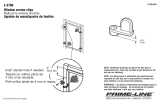
4.3 IF THE TOP TIRE BEAD IS
DIFFICULT TO MOUNT
Follow these instructions using the Bead Holding
Clamp (Fig. 4.2-4).
• After installing the bottom bead, inserts the
tire tool to the left of the bead head as shown
(Fig. 4.3-1). To protect decorative rims use
protective sleeve #EAA0247G04A (S).
Fig. 4.3-1
• Step on the foot pedal to rotate the turntable
clockwise until the tire lever is tight against the bead
head.
• Using your right hand push and hold the tire bead
opposite the bead head into the rim drop centre.
• Position the bead clamp #EAA0247G70A to hold
the tire bead into the rim drop centre (Fig. 4.2-4).
• As the turntable is turning use the tire tool in your
left hand to raise and guide the tire bead onto the
bead head (Fig. 4.3-2).
Fig. 4.3-2
• Continue to rotate the turntable until the top bead
is mounted.
Do not remove the tire tool or bead clamp until the foot
pedal is released.
NOTICE!
SOME TIRES HAVE A COLOR DOT THAT IS TO
BE KEPT ON THE OUTSIDE OF THE WHEEL AND
IS TO BE ALIGNED WITH THE VALVE STEM. IF
THIS IS THE CASE BE SURE TO ATTAIN PROPER
ALIGNMENT PRIOR TO TIRE INFLATION.
B. Lock the rim to the turntable and rotate it so that
the valve is at the 2 o’clock position. Place the tire
to be mounted on the rim. Swing the mount/demount
arm in so that the mount/demount head is in the
working position. (Fig. 4.2-3) Position the lower bead
on top of the mount/demount head and UNDER the
mounting fi nger of the mount/demount head (Fig. 4.2-
3). Turn the wheel clockwise (right pedal down) while
simultaneously pushing the tire down into the drop
center, opposite to the mount/demount head.
338
Fig. 4.2-3
C. Mount the upper bead following the directions
in section B. With low profi le tires the bead holding
clamp (option EAA0247G70A Fig. 4.2-4) can help to
prevent the top bead from prematurely seating during
the mounting cycle.
NOTE: Bead Holding Clamp must be removed prior to
coming full circle and impacting the mount/demount head.
896
Fig. 4.2-4

19
Snap-On EEWH329A
C. Lift the tire with both hands so that the upper bead
is sealed to the rim edge (Fig. 4.4-1).
NEVER STAND OVER TIRE WHEN ATTEMPTING
TO SEAT BEADS OR DURING INFLATION
340a
Fig. 4.4-1
D. Press the infl ation pedal down swiftly to the end of its
travel to activate the bead seater jets. (Fig. 4.4-1 item 1).
The top bead is already seated by the lifting motion.
Therefore, the air from the bead seater jets will enter
the tire impacting on the top sidewall and rebound into
the bottom sidewall driving it into place and seating the
bead, creating an air seal.
WHEN OPERATING THE BEAD SEATER, ALWAYS
WEAR SAFETY GLASSES TO AVOID INJURY TO EYES.
E. Install valve core, if removed. Complete infl ation to
manufacturer’s suggested pressure. Never exceed
pressure listed on tire sidewall.
4.4 INFLATION OF TUBELESS TIRES
Make sure that both beads are properly lubricated.
BEAD SEATING IS THE MOST DANGEROUS PART
OF MOUNTING A TIRE.
NEVER STAND OVER TIRE WHEN ATTEMPTING
TO SEAT BEADS OR DURING INFLATION
IT IS POSSIBLE TO INCORRECTLY MOUNT TIRES
THAT ARE 1/2” SMALLER IN DIAMETER THAN
THE RIM THAT THEY ARE MOUNTED ON. WHILE
THESE BEADS WILL SEAL, IT IS IMPOSSIBLE TO
GET THEM TO SEAT IN THEIR PROPER POSITION.
EXPLOSION OF A TIRE MAY CAUSE SEVERE
INJURY
SAFETY RESTRAINT ARM (OPTIONAL) MUST BE
IN PLACE PRIOR TO ATTEMPTING BEAD SEATING
OR INFLATION.
NEVER EXCEED THE MAXIMUM PRESSURE
ALLOWED BY THE TIRE MANUFACTURER.
IF YOU CLAMPED THE RIM FROM THE OUTSIDE
IT MUST BE UNCLAMPED WHEN INFLATING BUT
ONLY AFTER THE SRA IS IN PLACE.
THE OPERATOR MUST STAND CLEAR FROM THE
WHEEL WHEN INFLATING, AND PRESSURE MUST
BE MONITORED FREQUENTLY TO AVOID OVER
INFLATION.
BEFORE INFLATING A TIRE, CHECK THE
CONDITION OF THE TIRE AND THE RIM.
In fl at e ti r e a cc ord in g t o ma nu fa c tur er ’s
recommendations.
Due to unusual confi gurations or the stacking of tires
the infl ation process may be diffi cult. To assist with
this problem the Tire Changers are equipped with bead
seater jets integrated into the tabletop.
To utilize the bead seater proceed as follows:
A. Position the safety restraint arm (optional) over
center of wheel assembly. The safety arm is lifted
upward by grasping the safety restraint position knob
and lifting upward while simultaneously depressing
the anti-rotation lock arm. Swing SRA arm assembly
so the rubber retainer is centered over the rim. Note
that air pressure to the infl ation hose will not fl ow until
the arm is centered over the rim.
B. Connect the infl ation hose to the valve stem.

20
Snap-On EEWH329A
C. Infl ate the tube slightly: if held with the index fi nger
it should bend a little (Fig. 5.1-2).
342
Fig. 5.1-2
D. Mount the fi rst bead as described in section 4.2,
point B. Put the tube inside the tire and connect the
infl ation air line to the tube valve to hold the tube in
place. (Fig. 5.1-3). Mount the top bead following the
directions above.
Fig. 5.1-3 343
5.0 DEMOUNTING TUBE-TYPE
TIRES
A. For breaking the bead operate as described for the
tubeless tires in section 4.1, point A to F
.
In this case the valve is part of the tube.
NOTICE!
BE CAREFUL NOT TO DAMAGE THE TUBE
DURING THE BEAD-BREAKING OPERATION. THE
VALVE SHOULD BE OPPOSITE TO THE BLADE OF
THE BEAD BREAKER.
B. To demount the fi rst bead, place the valve at 2
o’clock position.
NOTICE!
BE CAREFUL NOT TO CATCH THE TUBE WITH
THE MOUNT/DEMOUNT TOOL, WHEN LIFTING THE
BEAD ON THE MOUNTING FINGER.
After demounting the fi rst bead carefully, remove the
tube before demounting the second bead, as described
in section 4.1.
5.1 MOUNTING TUBE-TYPE TIRES
A.
Perform steps described in section 4.2.A. DO NOT
lubricate
the tube. Talc can be used to assist with tire
positioning if necessary.
B. Confi rm that the tube is the correct size for the tire
to be mounted. (Fig. 5.1-1).
341
Fig. 5.1-1
1/78