STIEBEL ELTRON DCE-C 6-12 Trend Operation Instruction
- Taper
- Operation Instruction

OPERATION AND INSTALLATION
UTILISATION ET INSTALLATION
OPERACIÓN E INSTALACIÓN
KEZELÉS ÉS TELEPÍTÉS
RUKOVANJE I INSTALACIJA
ΧΕΙΡΙΣΜΌΣ ΚΑΙ ΕΓΚΑΤΑΣΤΑΣΗ
ЭКСПЛУАТАЦИЯ И УСТАНОВКА
Electronically controlled compact instantaneous water heater | Chauffe-eau
instantané compact à gestion électronique | Calentador instantáneo electrónico
compacto |
Ηλεκτρονικά ελεγχόενο κόπακτ στιγιαίο
θεραντήρα ροή | |
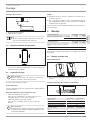
» DCE-C 6/8 Trend
» DCE-C 10/12 Trend

2 | DCE-C Trend www.stiebel-eltron.com
CONTENTS
SPECIAL INFORMATION
OPERATION
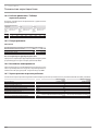
1. General information �����������������������������������������3
1.1 Safety instructions ����������������������������������������������� 3
1.2 Other symbols in this documentation ����������������������� 3
1.3 Units of measurement ������������������������������������������ 4
2. Safety ���������������������������������������������������������� 4
2.1 Intended use ������������������������������������������������������ 4
2.2 General safety instructions ������������������������������������ 4
2.3 Test symbols ������������������������������������������������������ 4
3. Appliance description ���������������������������������������4
4. Cleaning, care and maintenance ���������������������������5
5. Troubleshooting ����������������������������������������������5
INSTALLATION
6. Safety ���������������������������������������������������������� 5
6.1 General safety instructions ������������������������������������ 5
6.2 Shower operation������������������������������������������������ 5
6.3 Instructions, standards and regulations �������������������� 5
7. Appliance description ���������������������������������������6
7.1 Standard delivery ������������������������������������������������ 6
7.2 Accessories �������������������������������������������������������� 6
8. Preparation ���������������������������������������������������6
8.1 Installation site ��������������������������������������������������� 6
8.2 Minimum clearances �������������������������������������������� 6
8.3 Water installation ������������������������������������������������ 6
9. Installation ����������������������������������������������������7
9.1 Standard installation on finished walls ��������������������� 7
10. Commissioning �����������������������������������������������8
10.1 Changing the connected load via the jumper slot ��������� 8
10.2 Initial start-up ���������������������������������������������������� 8
10.3 Recommissioning ������������������������������������������������ 9
11. Appliance shutdown �����������������������������������������9
12. Alternative installation methods ���������������������������9
12.1 Electrical connection from above on unfinished walls ��� 9
12.2 Electrical connection from below on unfinished walls �� 10
12.3 Electrical connection with short power cable ������������ 10
12.4 Electrical connection from the side on finished walls ��� 10
12.5 Water installation on unfinished walls ��������������������� 10
12.6 Operation with preheated water ���������������������������� 11
13. Service information ���������������������������������������� 12
14. Troubleshooting �������������������������������������������� 12
15. Maintenance ������������������������������������������������ 13
15.1 Draining the appliance ���������������������������������������� 13
15.2 Cleaning the strainer �������������������������������������������13
16. Specification ������������������������������������������������ 14
16.1 Dimensions and connections ��������������������������������� 14
16.2 Wiring diagram ������������������������������������������������� 14
16.3 DHW output ������������������������������������������������������ 14
16.4 Application areas/ conversion table ����������������������� 15
16.5 Pressure drop ��������������������������������������������������� 15
16.6 Fault conditions ������������������������������������������������� 15
16.7 Energy consumption data ������������������������������������� 15
16.8 Data table �������������������������������������������������������� 16
GUARANTEE
ENVIRONMENT AND RECYCLING

ENGLISH
www.stiebel-eltron.com DCE-C Trend | 3
SPECIAL INFORMATION | OPERATION
General information
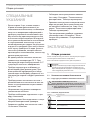
SPECIAL INFORMATION
- The appliance may be used by children aged3
and older and persons with reduced physical,
sensory or mental capabilities or a lack of ex-
perience and know-how, provided that they
are supervised or they have been instructed
on how to use the appliance safely and have
understood the potential risks. Children must
never play with the appliance. Cleaning and
user maintenance must not be carried out by
children without supervision.
- During operation, the tap can reach tempera-
tures up to 70°C. There is a risk of scalding at
outlet temperatures in excess of 43°C.
- The appliance is suitable for supplying a
shower (shower operation). When using pre-
heated water, ensure that the inlet tempera-
ture does not exceed 55°C.
- Ensure the appliance can be separated from
the power supply by an isolator that discon-
nects all poles with at least 3mm contact
separation.
- The specified voltage must match the power
supply.
- The appliance must be connected to the earth
conductor.
- The appliance must be permanently connect-
ed to fixed wiring.
- Secure the appliance as described in chapter
"Installation/ Installation".
- Observe the application limits (see chapter
"Installation/ Specification/ Data table").
- The specific water resistivity of the mains
water supply must not be undershot (see
chapter "Installation/ Specification/ Data
table").
- Drain the appliance as described in chapter
"Installation/ Maintenance/ Draining the
appliance".
OPERATION
1. General information
The chapters "Special information" and "Operation" are intended
for both users and qualified contractors.
The chapter "Installation" is intended for qualified contractors.
Note
Read these instructions carefully before using the appli-
ance and retain them for future reference.
Pass on the instructions to a new user if required.
1.1 Safety instructions
1.1.1 Structure of safety instructions
!
KEYWORD Type of risk
Here, possible consequences are listed that may result
from failure to observe the safety instructions.
f Steps to prevent the risk are listed.
1.1.2 Symbols, type of risk
Symbol Type of risk
Injury
Electrocution
Burns
(burns, scalding)
1.1.3 Keywords
KEYWORD Meaning
DANGER Failure to observe this information will result in serious
injury or death.
WARNING Failure to observe this information may result in serious
injury or death.
CAUTION Failure to observe this information may result in non-seri-
ous or minor injury.
1.2 Other symbols in this documentation
Note
General information is identified by the adjacent symbol.
f Read these texts carefully.
Symbol Meaning
Material losses
(appliance damage, consequential losses and environmen-
tal pollution)
Appliance disposal
!
!

OPERATION
Safety
4 | DCE-C Trend www.stiebel-eltron.com
f This symbol indicates that you have to do something. The ac-
tion you need to take is described step by step.
1.3 Units of measurement
Note
All measurements are given in millimetres unless oth-
erwise stated.
2. Safety
2.1 Intended use
This appliance is suitable for heating domestic hot water or for
reheating preheated water. The appliance can supply one or more
draw-off points.
Water will not be reheated if the maximum inlet temperature for
reheating is exceeded.
The appliance is intended for domestic use. It can be used safely
by untrained persons. The appliance can also be used in non-do-
mestic environments, e.g. in small businesses, as long as it is
used in the same way.
Any other use beyond that described shall be deemed inappro-
priate. Observation of these instructions and of the instructions
for any accessories used is also part of the correct use of this
appliance.
2.2 General safety instructions
CAUTION Burns
During operation, the tap can reach temperatures up
to 70°C.
There is a risk of scalding at outlet temperatures in ex-
cess of 43°C.
CAUTION Burns
When operating with preheated water, for example
when using a solar thermal system, ensure that the inlet
temperature does not exceed 55°C.
f Limit the inlet temperature with an upstream cen-
tral thermostatic valve.
!
WARNING Injury
The appliance may be used by children aged3 and older
and persons with reduced physical, sensory or mental
capabilities or a lack of experience and know-how, pro-
vided that they are supervised or they have been in-
structed on how to use the appliance safely and have
understood the potential risks. Children must never play
with the appliance. Cleaning and user maintenance must
not be carried out by children without supervision.
!
Material losses
The user should protect the appliance and its tap against
frost.
Note
In order to comply with protection rating IP25, coun-
tersunk screws must be used to secure the appliance to
the wall.
2.3 Test symbols
See type plate on the appliance.
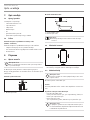
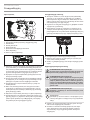
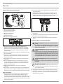
3. Appliance description
The appliance switches on automatically as soon as you open the
hot water valve on the tap. When you close the tap, the appliance
switches off again automatically.
The appliance heats water as it flows through it. The DHW outlet
temperature is set to a fixed value. This is max. 55°C, which can
be reduced by mixing in cold water at the tap.
Upwards of a certain flow rate, the control unit selects the required
heating output, subject to the cold water temperature.
The electronically controlled compact instantaneous water heat-
er with automatic output matching maintains a consistent outlet
temperature. It does so irrespective of the inlet temperature, up
to the maximum output of the appliance.
Heating system
The bare wire heating system is enclosed within a pressure-tested
plastic jacket. The heating system with its stainless steel heater
spiral is suitable for hard and soft water areas and is largely in-
susceptible to scale build-up. The heating system ensures rapid
and efficient DHW provision.
Note
The appliance is equipped with an air detector that large-
ly prevents damage to the heating system. If, during op-
eration, air is drawn into the appliance, the appliance
shuts down heating operation for one minute to protect
the heating system.
Following an interruption to the water supply
!
Material losses
To ensure that the bare wire heating system is not dam-
aged following an interruption to the water supply, the
appliance must be restarted by taking the following steps.
f Disconnect the appliance from the power supply by
removing the fuses/tripping the MCBs.
f Vent the appliance and the cold water inlet line (see
chapter “Installation/ Commissioning/ Initial start-
up”).
f Switch the power back ON.

ENGLISH
www.stiebel-eltron.com DCE-C Trend | 5
OPERATION | INSTALLATION
Cleaning, care and maintenance
Recommended settings
Your instantaneous water heater offers maximum precision and
maximum convenience in DHW provision. If you do nonetheless
operate the appliance with a thermostatic valve, we recommend
adjusting the required set temperature on the thermostatic valve.
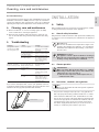
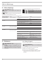
4. Cleaning, care and maintenance
f Never use abrasive or corrosive cleaning agents. A damp
cloth is sufficient for cleaning the appliance.
f Check the taps regularly. Limescale deposits at the tap out-
lets can be removed using commercially available descaling
agents.
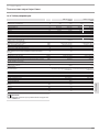
5. Troubleshooting
Problem Cause Remedy
The appliance will not
start despite the DHW
valve being fully open.
There is no power.
Check the fuses/ MCBs in
your fuse box/ distribu-
tion board.
The aerator in the tap
or the shower head is
scaled up or dirty.
Clean and/or descale the
aerator or shower head.
The water supply has
been interrupted.
Vent the appliance and
the cold water inlet line
(see chapter "Installa-
tion/ Commissioning/
Initial start-up").
When hot water is being
drawn off, cold water
flows for a short period.
The air sensor is detect-
ing air in the water. It
briefly switches off the
heating output.
The appliance restarts
automatically after
1minute.
Boiling noises are heard
during operation.
The appliance is not
vented.
Vent the appliance (see
chapter "Installation/
Commissioning/ Initial
start-up").
The supply pressure is
too low.
Ensure that the mini-
mum supply pressure is
achieved (see chapter
"Installation/ Specifica-
tion/ Data table").
If you cannot remedy the fault, contact your qualified contractor.
To facilitate and speed up your enquiry, please provide the serial
number from the type plate (000000-0000-000000).
Nr.: 000000-0000-00000
D0000073621
INSTALLATION
6. Safety
Only a qualified contractor should carry out installation, commis-
sioning, maintenance and repair of the appliance.
6.1 General safety instructions
We guarantee trouble-free function and operational reliability only
if original accessories and spare parts intended for the appliance
are used.
!
Material losses
Observe the maximum inlet temperature. Higher tem-
peratures may damage the appliance. You can limit the
maximum inlet temperature by installing a central ther-
mostatic valve.
WARNING Electrocution
This appliance contains capacitors which are discharged
when disconnected from the power supply. The capacitor
discharge voltage may briefly exceed60VDC.
6.2 Shower operation
CAUTION Burns
When operating with preheated water, for example
when using a solar thermal system, ensure that the inlet
temperature does not exceed 55°C.
f Limit the inlet temperature with an upstream cen-
tral thermostatic valve.
6.3 Instructions, standards and regulations
Note
Observe all applicable national and regional regulations
and instructions.
- The protection rating IP25 (hoseproof) is only guaranteed
with a properly fitted cable grommet and the use of counter-
sunk screws Ø4.5mm with a max. head diameter of 9mm.
- The electrical resistivity of the water must not fall below that
stated on the type plate. In a linked water network, take into
consideration the lowest electrical resistivity of the water.
Your water supply utility will advise you of the electrical re-
sistivity or conductivity of the water in your area.

INSTALLATION
Appliance description
6 | DCE-C Trend www.stiebel-eltron.com
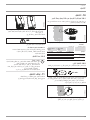
7. Appliance description
7.1 Standard delivery
The following are delivered with the appliance:
- 2 x 45° twin connectors
- 2 flat gaskets
- 2 O-rings
- Cable grommet
- Strainer
- Flow limiter
- Jumper for output changeover, attached
7.2 Accessories
Installation kit for water installation on unfinished walls
(200016 - UP-Kit EU)
The installation kit for water installation on unfinished walls con-
tains:
- 2 x grommets to seal the apertures in the appliance back
panel
- Strainer with sealed edge for installation on the 45°twin
connector
- Flat gasket
8. Preparation
8.1 Installation site
!
Material losses
Install the appliance in a room that is free from the risk
of frost.
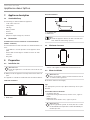
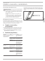
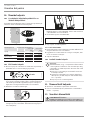
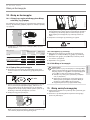
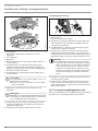
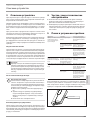
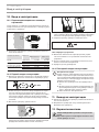
f Always install the appliance vertically and near the draw-off
point.
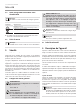
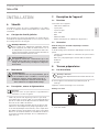
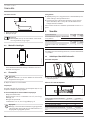
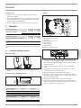
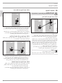
The appliance is suitable for undersink and oversink installation.
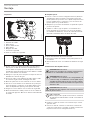
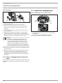
Undersink installation
D0000073616
1
2
1 Cold water inlet
2 DHW outlet
Oversink installation
12
D0000073617
1 Cold water inlet
2 DHW outlet
Note
f Install the appliance flush to the wall. The wall must
have sufficient load bearing capacity.
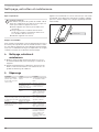
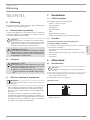
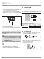
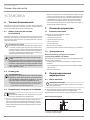
8.2 Minimum clearances
≥50≥50
≥50
≥100
D0000079442
f Maintain the minimum clearances to ensure trouble-free op-
eration of the appliance and facilitate maintenance work.
8.3 Water installation
!
Material losses
Carry out all water connection and installation work in
accordance with regulations.
f Flush the water line thoroughly.
Taps
Use appropriate pressure taps. Open vented taps are not per-
missible.
Permissible water line materials
- Cold water inlet line:
Pipes made from galvanised steel, stainless steel, copper or
plastic
- DHW outlet line:
Pipes made from stainless steel, copper or plastic
!
Material losses
If plastic pipework systems are used, take into account
the maximum inlet temperature and the maximum per-
missible pressure.

INSTALLATION
Installation
ENGLISH
www.stiebel-eltron.com DCE-C Trend | 7
Flow rate
f Ensure that the flow rate for switching on the appliance is
achieved.
f If the required flow rate is not achieved when the draw-off
valve is fully open, remove the flow limiter from the cold
water inlet.
If required, the pressure in the water installation can also be
raised.
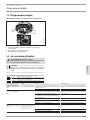
9. Installation
Factory settings
Trend
Trend
Connected load in kW @ 220V 8.0 12.0
@ 230V 8.7 13.1
Standard installation
Trend
Trend
Electrical connection from below, installa-
tion on finished walls
x x
Water connection, installation on finished
walls
x x
For further installation options, see chapter "Alternative instal-
lation methods".
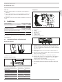
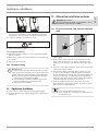
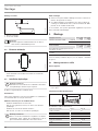
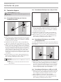
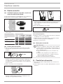
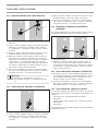
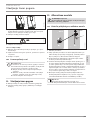
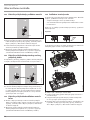
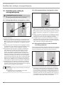
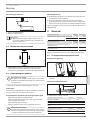
9.1 Standard installation on finished walls
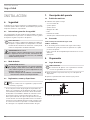
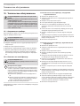
Opening the appliance
D0000073641
f Open the appliance by undoing the screw and lifting up the
appliance cover.
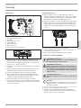
Preparing the power cable
B
A
D0000077179
f Prepare the power cable.
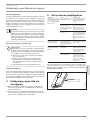
Position on finished walls Dimension A Dimension B
Bottom, centre 30 120
Bottom, left side of appliance 20 90
Bottom, right side of appliance 20 90
Top, right side of appliance 20 80
Position on unfinished walls Dimension A Dimension B
Bottom 20 90
Top 20 80
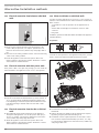
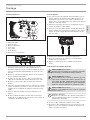
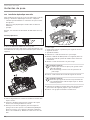
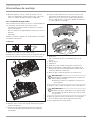
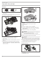
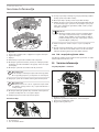
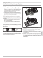
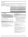
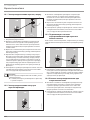
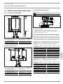
Preparation
D0000077976
4
3
2
1
57 6
1 Strainer
2 Flow limiter
3 O-rings
4 45° twin connector
5 Flat gaskets
6 Cable grommet
7 Locking screws
f Undo the locking screws.
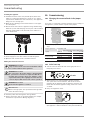
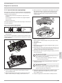
D0000085450
f Push/break out the required apertures where marked on the
appliance back panel for the power cable and twin connec-
tors. Use a suitable flat tool when doing so. Deburr any sharp
edges with a file.
f Remove the transport protection plugs from the water con-
nection pipes.
f Cut a hole in the cable grommet to fit the selected connecting
cable. Fit the cable grommet.
f Fit the O-rings into the groove on the twin connectors.
f Push the twin connectors into the apertures in the appliance
back panel and fit them to the appliance connection pipes
using flat gaskets (torque 8Nm).
f Secure the twin connectors with the locking screws.
f Insert the flow limiter and strainer in the twin connector of
the cold water connection. Note the orientation of the flow
limiter.

INSTALLATION
Commissioning
| DCE-C Trend www.stiebel-eltron.com
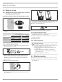
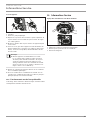
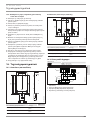
Installing the appliance
f Push/break out the lower slots (175mm apart) in the back
panel for securing the appliance (for positions, see chapter
"Specification/ Dimensions and connections"). The upper two
fixing holes are already open.
f Mark out the 4drilling positions with reference to the appli-
ance back panel.
f Drill the holes and secure the appliance using suitable fixing
materials (screws and rawl plugs are not part of the standard
delivery): Countersunk screw, Ø4.5mm, max. diameter of
screw-head 9mm.
D0000073844
f Fit a suitable pressure tap.
f Fit the tap pipes to the twin connectors with flat gaskets.
f Open the shut-off valve in the cold water inlet line.
Making the electrical connection
WARNING Electrocution
Carry out all electrical connection and installation work
in accordance with relevant regulations.
WARNING Electrocution
The connection to the power supply is only permissible
as a permanent connection in conjunction with the re-
movable cable grommet. Ensure the appliance can be
separated from the power supply by an isolator that dis-
connects all poles with at least 3mm contact separation.
WARNING Electrocution
Ensure that the appliance is earthed.
!
Material losses
Observe the type plate. The specified rated voltage must
match the mains voltage.
f Push the power cable through the cable grommet.
f Connect the power cable to the mains terminal (see chapter
"Installation/ Specification/ Wiring diagram").
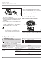
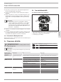
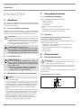
10. Commissioning
10.1 Changing the connected load via the jumper
slot
If you select a connected load other than the factory setting for
the appliance, you will need to reposition the jumper.
1
2
D0000082938
f Install the jumper in the required position on the "Pmax" pin
strip.
Jumper position Connected load
1 [low] @ 220V 6.0kW 10.0kW
@ 230V 6.6kW 11.0kW
2 [high]
@ 220V 8.0kW 12.0kW
Factory setting @ 230V 8.7kW 13.1kW
No jumper [low]
@ 220V 6.0kW 10.0kW
@ 230V 6.6kW 11.0kW
10.2 Initial start-up
f Tick the selected connected load on the type plate. Use a
ballpoint pen to do this.
≥ 3 min.
on
15 x
off
D0000101520
f Open and close all connected draw-off valves 15 times
over a period of at least 3 minutes, until all air has been
purged from the pipework and the appliance. Vent the cold
water inlet line and the appliance using a flow rate of least
3.5l/min.
f Carry out a tightness check.
D0000073622
f Activate the safety switch by firmly pressing the reset button
(the appliance is delivered with the safety switch disabled).

INSTALLATION
Appliance shutdown
ENGLISH
www.stiebel-eltron.com DCE-C Trend | 9
D0000073642
f Hook the appliance cover into the appliance back panel at the
top rear. Pivot the appliance cover downwards. Check that
the appliance cover is securely seated both top and bottom.
f Secure the appliance cover with the screw.
D0000053281
f Switch on the power supply.
10.2.1 Appliance handover
f Explain the appliance function to users and familiarise them
with how it works.
f Make the user aware of potential dangers, especially the risk
of scalding.
f Hand over the instructions.
10.3 Recommissioning
!
Material losses
To ensure that the bare wire heating system is not dam-
aged following an interruption to the water supply, the
appliance must be restarted by taking the following steps.
f Disconnect the appliance from the power supply by
removing the fuses/tripping the MCBs.
f Vent the appliance and the cold water inlet line (see
chapter "Commissioning/ Initial start-up").
f Switch the power back ON.
11. Appliance shutdown
f Isolate all poles of the appliance from the power supply.
f Drain the appliance (see chapter "Maintenance/ Draining the
appliance").
12. Alternative installation methods
WARNING Electrocution
Before performing any work on the appliance, discon-
nect all poles from the power supply.
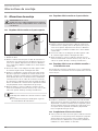
12.1 Electrical connection from above on unfinished
walls
D0000073620
2
1
1 Cable grommet
2 Cable routing
f Break out the required aperture in the back panel for the
power cable (for positions, see chapter "Specification/ Di-
mensions and connections"). Deburr any sharp edges with a
file.
f Cut a hole in the cable grommet to fit the selected connecting
cable. Fit the cable grommet.
f Reposition the mains terminal from the bottom to the top.
To do so, unclip the mains terminal by pushing it firmly to
the left and pulling it forwards. Turn the mains terminal with
connecting cables 180° clockwise. Lay the internal wiring
under the cable guide. Clip the mains terminal in by pushing
it inwards and to the left until it clicks into place.
f Install the appliance and connect the power cable to the
mains terminal as described in chapter "Installation/ Stand-
ard installation on finished walls".
Note
Disconnecting the mains terminal at the top:
f Use a screwdriver to disengage the locking tab from
the right-hand side.

INSTALLATION
Alternative installation methods
10 | DCE-C Trend www.stiebel-eltron.com
12.2 Electrical connection from below on unfinished
walls
D0000079465
1
1 Cable grommet
f Break out the required aperture in the back panel for the
power cable (for positions, see chapter "Specification/ Di-
mensions and connections"). Deburr any sharp edges with a
file.
f Cut a hole in the cable grommet to fit the selected connecting
cable. Fit the cable grommet.
f Install the appliance and connect the power cable to the
mains terminal as described in chapter "Installation/ Stand-
ard installation on finished walls".
12.3 Electrical connection with short power cable
If the power cable is not quite long enough, you can install the
mains terminal in the appliance a little closer to the aperture.
D0000073648
1
1 Cable grommet
f Reposition the mains terminal from the top to the bottom. To
do so, unclip the mains terminal by pushing it firmly to the
left and pulling it forwards. Clip the mains terminal in at the
bottom by pushing it inwards and to the left until it clicks
into place.
12.4 Electrical connection from the side on finished
walls
f Cut and break out the required aperture in the appliance
back panel and appliance cover for the power cable (for po-
sitions, see chapter "Specification/ Dimensions and connec-
tions"). Deburr any sharp edges with a file.
f Install the appliance and connect the power cable to the
mains terminal as described in chapter "Installation/ Stand-
ard installation on finished walls".
12.5 Water installation on unfinished walls
You will need the appropriate accessories to carry out the in-
stallation. The installation kit for water installation on unfinished
walls contains:
- 2 x grommets to seal the apertures in the appliance back
panel
- Strainer with sealed edge for installation on the 45°twin
connector
- Flat gasket
In addition, you will need the flow limiter included in the appliance
standard delivery.
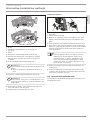
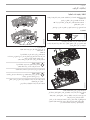
Preparation
44-46
D0000073660
f Insert and seal the 45°twin connectors.
To break out the apertures in the appliance back panel, you will
need to remove the function module from the back panel.
1.
4.
5.
2.
3.
D0000077971
f Undo the screw and disengage the locking tab.
f Push the function module on the back panel gently
backwards.
f Remove the function module from the appliance back panel
by pulling it slightly forwards and lifting it off.
f Push/break out the required apertures for the water connec-
tions in the back panel from behind (for positions, see chap-
ter "Specification/ Dimensions and connections"). Deburr any
sharp edges with a file.

INSTALLATION
Alternative installation methods
ENGLISH
www.stiebel-eltron.com DCE-C Trend | 11
1.
2.
3.
4.
D0000077974
1 2 3
4
5
1 Flow limiter
2 O-ring
3 Cold water pipe bend with recess for spring clip
4 Spring clip
5 Heater
f Remove the cold water pipe bend and the O-ring.
f Insert the flow limiter (part of the appliance standard
delivery) in the cold water inlet of the heater. Note the
orientation.
f Fit the cold water pipe bend with the O-ring.
!
Material losses
The O-ring must be fitted to prevent the appliance from
leaking.
f As part of installation, check that the O-ring is in
place.
f Secure the cold water pipe bend with the spring clip.
!
Material losses
Ensure that the spring clip is located behind the recess
in the pipe bend and that it is securely holding the pipe
bend in place.
f Fit the function module on the appliance back panel in re-
verse order until it clicks into place.
f Secure the function module with the screw.
Installing the appliance
D0000073842
321
1 Grommets
2 Flat gasket
3 Strainer with sealed edge
f Mark out the 2drilling positions in the upper section of the
appliance back panel with reference to the appliance back
panel.
f Fit the grommets in the appliance back panel from the front.
f Drill the holes and secure the appliance using suitable fixing
materials (screws and rawl plugs are not part of the standard
delivery): Countersunk screw, Ø4.5mm, max. diameter of
screw-head 9mm.
Note
f Install the appliance flush to the wall. If necessary,
additionally secure the appliance at the 2 lower
attachment points. To do this, push/break out the
lower slots (175mm apart) in the appliance back
panel (for positions, see chapter "Specification/ Di-
mensions and connections").
f Remove the transport protection plugs from the water con-
nection pipes.
f Secure the DHW connection pipe with a flat gasket and the
cold water inlet line with the sealed-edge strainer (from the
accessories) to the twin connectors.
12.6 Operation with preheated water
You can limit the maximum inlet temperature by installing a cen-
tral thermostatic valve.

INSTALLATION
Service information
12 | DCE-C Trend www.stiebel-eltron.com
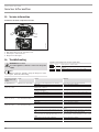
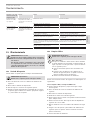
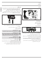
13. Service information
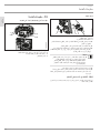
Connection overview/ component overview
D0000082950
1
2
3
4
1 Flow meter
2 High limit safety cut-out, automatic reset
3 Pin strip for connected load
4 Diagnostic traffic lights
14. Troubleshooting
WARNING Electrocution
To test the appliance, it must be connected to the power
supply.
Note
When testing the appliance using the diagnostic traffic
lights, water must be flowing.
Signals of the diagnostic traffic lights (LED)
Red Lights up in the event of a fault
Yellow Lights up in heating mode/flashes when output limit
reached
Green Flashing: Appliance connected to power supply
Diagnostic traffic
lights (draw-off
mode)
Fault Cause Remedy
No LED illuminates Appliance does not heat up
One or more power supply phases are missing Check the fuses in the distribution board
PCB faulty Replace the function module
Green flashing,
yellow off, red off
No DHW
Appliance starting flow rate not reached; shower
head/aerator scaled up
Descale/replace the shower head/aerator
Appliance starting flow rate not reached; strainer in
cold water inlet dirty
Cleaning the strainer
Flow meter not plugged in Check plug-in connection; correct if necessary
Flow meter faulty or dirty Replace the function module
PCB faulty Replace the function module
Green flashing,
yellow on, red off
No DHW; outlet temperature
does not match set value
Tap faulty Replace tap
Heating system faulty Replace the function module
PCB faulty Replace the function module
Green flashing,
yellow off, red on
No DHW; outlet temperature
does not match set value
Air detection has responded Continue draw-off for >1min
Safety switch not activated during "Commissioning" Activate the safety switch by firmly pressing the reset
button
Safety switch was triggered by high limit safety cut-
out
Check high limit safety cut-out (plug-in connection,
connecting cable); activate safety switch
Safety switch responds again after high limit safety
cut-out has been checked; high limit safety cut-out
faulty
Replace high limit safety cut-out; activate safety
switch and draw-off with maximum set value >1min
Safety switch responds again; PCB faulty Replace the function module
PCB faulty Replace the function module

INSTALLATION
Maintenance
ENGLISH
www.stiebel-eltron.com DCE-C Trend | 13
15. Maintenance
WARNING Electrocution
Before performing any work on the appliance, discon-
nect all poles from the power supply.
This appliance contains capacitors which are discharged
when disconnected from the power supply. The capacitor
discharge voltage may briefly exceed60VDC.
15.1 Draining the appliance
The appliance can be drained for maintenance work.
WARNING Burns
Hot water may escape when you drain the appliance.
f Close the shut-off valve in the cold water inlet line.
f Open all draw-off valves.
f Undo the water connections on the appliance.
f Store the dismantled appliance free from the risk of frost, as
water residues remaining inside the appliance can freeze and
cause damage.
15.2 Cleaning the strainer
WARNING Burns
Hot water may escape when you drain the appliance.
!
Material losses
To ensure that the bare wire heating system is not dam-
aged following an interruption to the water supply, the
appliance must be recommissioned by taking the follow-
ing steps.
f Disconnect the appliance from the power supply by
removing the fuses/tripping the MCBs.
f Vent the appliance and the cold water inlet line (see
chapter "Commissioning/ Initial start-up").
f Switch on the power supply again.
The strainer in the cold water threaded fitting must be cleaned
regularly.
15.2.1 Cleaning the strainer, standard installation on finished
walls
f Isolate the appliance from the power supply.
f Close the shut-off valve in the cold water inlet line.
f Open all draw-off valves.
f Remove the cold water threaded fitting.
f Remove the strainer from the twin nipple using a flat-blade
screwdriver. Clean the strainer.
f Reinsert the strainer. Screw the cold water connection pipe
onto the twin nipple.
f Open the shut-off valve in the cold water inlet line.
f Vent the appliance and the cold water inlet line (see chapter
"Commissioning/ Initial start-up").
f Switch on the power supply.
15.2.2 Cleaning the strainer, installation on unfinished walls
f Isolate the appliance from the power supply.
f Close the shut-off valve in the cold water inlet line.
f Open all draw-off valves.
f Open the appliance by undoing the screw and lifting up the
appliance cover.
f Unscrew the cold water connection pipe from the twin nip-
ple. Pivot the cold water connection pipe upwards.
f Remove the strainer from the twin nipple. Clean the strainer.
f Screw the cold water connection pipe and the strainer with
sealed edge onto the twin nipple.
f Open the shut-off valve in the cold water inlet line.
f Vent the appliance and the cold water inlet line (see chapter
"Commissioning/ Initial start-up").
f Check the cold water connection for leaks.
f Hook the appliance cover into the appliance back panel at the
top rear. Pivot the appliance cover downwards. Check that
the appliance cover is securely seated both top and bottom.
Secure the appliance cover with the screw.
f Switch on the power supply.

INSTALLATION
14 | DCE-C Trend www.stiebel-eltron.com
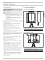
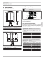
16. Specification
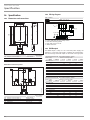
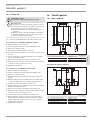
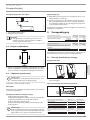
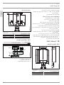
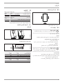
16.1 Dimensions and connections
372
358
343
14
97
217
140
175
100
c01c06
35
32
b02
380
D0000084885
DCE-C Trend
b02 Entry for electrical cables I Finished walls
c01 Cold water inlet Male thread G 1/2 A
c06 DHW outlet Male thread G 1/2 A
Alternative connection options
100
c01c06
b02
72
330
b02
b02
69
35
336
b02
b03
30
61
15
b03
D0000073720
DCE-C Trend
b02 Entry for electrical cables I Finished walls
b03 Entry for electrical cables II Unfinished walls
c01 Cold water inlet Male thread G 1/2 A
c06 DHW outlet Male thread G 1/2 A
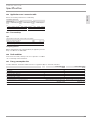
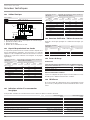
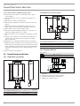
16.2 Wiring diagram
DCE-C Trend
L L
2/GRD ~ 220 / 230V
L N
1/N/PE ~ 220 / 230V
N
L
L
L
D0000077991
1
3
4
2
1 Power PCB with integral safety switch
2 Bare wire heating system
3 High limit safety cut-out
4 Mains terminal
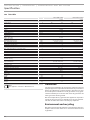
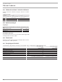
16.3 DHW output
The DHW output is subject to the connected power supply, the
appliance's connected load and the cold water inlet temperature.
The rated voltage and rated output can be found on the type plate.
Connected load in kW
Rated voltage Cold water inlet temperature
DCE-C 6/8 Trend
6.0 2.6 3.1 3.7 4.8
8.0 3.5 4.1 5.0 6.3
6.6 2.9 3.4 4.1 5.2
8.7 3.8 4.4 5.4 6.9
DCE-C 10/12 Trend
10.0 4.3 5.1 6.2 7.9
12.0 5.2 6.1 7.5 9.5
11.0 4.8 5.6 6.8 8.7
13.1 5.7 6.7 8.1 10.4
Connected load in kW
Rated voltage Cold water inlet temperature
DCE-C 6/8 Trend
6.0 1.9 2.1 2.4 2.9
8.0 2.5 2.9 3.3 3.8
6.6 2.1 2.4 2.7 3.1
8.7 2.8 3.1 3.6 4.1
DCE-C 10/12 Trend
10.0 3.2 3.6 4.1 4.8
12.0 3.8 4.3 4.9 5.7
11.0 3.5 3.9 4.5 5.2
13.1 4.2 4.7 5.3 6.2

INSTALLATION
ENGLISH
www.stiebel-eltron.com DCE-C Trend | 15
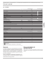
16.4 Application areas/ conversion table
Electrical resistivity and electrical conductivity.
Standard specifica-
Resis-
tivity
ρ≥
Conductivity ≤
Resis-
tivity
ρ≥
Conductivity ≤
Resis-
tivity
ρ≥
Conductivity ≤
Ωcm mS/m μS/cm Ωcm mS/m μS/cm Ωcm mS/m μS/cm
1100 91 910 970 103 1031 895 112 1117
16.5 Pressure drop
Taps
Mono lever mixer tap, approx. MPa 0.04 - 0.08
Thermostatic valve, approx. MPa 0.03 - 0.05
Shower head, approx. MPa 0.03 - 0.15
Sizing the pipework
When calculating the size of the pipework, an appliance pressure
drop of 0.1MPa is recommended.
16.6 Fault conditions
In the event of a fault, loads up to 80°C at a pressure of 1.0MPa
can occur briefly in the installation.
16.7 Energy consumption data
Product datasheet: Conventional water heaters to regulation (EU) no. 812/2013 | 814/2013
238148 238149
Manufacturer STIEBEL ELTRON STIEBEL ELTRON
Load profile XS XS
Energy efficiency class A A
Energy conversion efficiency % 39 39
Annual power consumption kWh 472 472
Default temperature setting °C 55 55
Sound power level dB(A) 15 15
Special information on measuring efficiency Measured with integral flow limiter and
maximum output
Measured with integral flow limiter and
maximum output
Daily power consumption kWh 2.161 2.163

16 | DCE-C Trend www.stiebel-eltron.com
16.8 Data table
238148 238149
Electrical data
Rated voltage V 220 230 220 230
Rated output kW 6.0/8.0 6.6/8.7 10.0/12.0 11.0/13.1
Rated current A 27.3/36.4 28.5/38.0 45.5/54.5 47.8/57.0
Fuse protection A 30/40 30/40 50/60 50/60
Frequency Hz 50/60 50/60 50/60 50/60
Phases 1/N/PE 1/N/PE
Resistivity ρ15 ≥ Ω cm 1100 1100
Conductivity 15 ≤ μS/cm 910 910
Max. mains impedance at 50Hz Ω 0.0385 0.0368 0.0257 0.0245
Connections
Water connection G 1/2 A G 1/2 A
Application limits
Minimum supply pressure MPa 0.18 (1.8 bar / 26 psi) 0.18 (1.8 bar / 26 psi)
Max. permissible pressure MPa 1 (10 bar / 150 psi) 1 (10 bar / 150 psi)
Max. inlet temperature for reheating °C 55 55
Temperature setting range °C 55 55
Values
Max. inlet temperature (e.g. pasteurisation) °C 70 70
On l/min 1.3 1.3
Flow rate at 28K l/min 3.1/4.1 @ 220V 5.1/6.2 @ 220V
Flow rate at 50K l/min 1.7/2.3 @ 220V 2.9/3.5 @ 220V
Pressure drop for flow rate at 50K (without flow limiter) MPa 0.01/0.01 0.02/0.03
Flow rate limit at l/min 4 5
Hydraulic data
Nominal capacity l 0.277 0.277
Versions
Type of installation Oversink/ undersink Oversink/ undersink
Adjustable connected load X X
Protection class 1 1
Insulating block Plastic Plastic
Heating system heat generator Bare wire Bare wire
Cover and back panel Plastic Plastic
Colour White White
IP rating IP25 IP25
Dimensions
Height mm 372 372
Width mm 217 217
Depth mm 97 97
Weights
Weight kg 2.5 2.5
Note
The appliance conforms to IEC 61000-3-12.
Guarantee
The guarantee conditions of our German companies do not
apply to appliances acquired outside of Germany. In countries
where our subsidiaries sell our products a guarantee can only
be issued by those subsidiaries. Such guarantee is only grant-
ed if the subsidiary has issued its own terms of guarantee. No
other guarantee will be granted.
We shall not provide any guarantee for appliances acquired in
countries where we have no subsidiary to sell our products.
This will not aect warranties issued by any importers.
Environment and recycling
We would ask you to help protect the environment. After use,
dispose of the various materials in accordance with national
regulations.
GUARANTEEGUARANTEE

FRANÇAIS
www.stiebel-eltron.com DCE-C Trend | 17
TABLE DES MATIÈRES
REMARQUES PARTICULIÈRES
UTILISATION
1. Remarques générales ������������������������������������� 18
1.1 Consignes de sécurité ������������������������������������������ 18
1.2 Autres pictogrammes utilisés dans cette
documentation �������������������������������������������������� 19
1.3 Unités de mesure ����������������������������������������������� 19
2. Sécurité ����������������������������������������������������� 19
2.1 Utilisation conforme ������������������������������������������� 19
2.2 Consignes de sécurité générales ���������������������������� 19
2.3 Label de conformité �������������������������������������������� 19
3. Description de l’appareil ���������������������������������� 19
4. Nettoyage, entretien et maintenance �������������������� 20
5. Dépannage �������������������������������������������������� 20
INSTALLATION
6. Sécurité ����������������������������������������������������� 21
6.1 Consignes de sécurité générales ����������������������������21
6.2 Mode douche ���������������������������������������������������� 21
6.3 Prescriptions, normes et réglementations����������������� 21
7. Description de l’appareil ���������������������������������� 21
7.1 Fourniture �������������������������������������������������������� 21
7.2 Accessoires ������������������������������������������������������� 21
8. Travaux préparatoires ������������������������������������� 21
8.1 Lieu d’installation ����������������������������������������������� 21
8.2 Distances minimales ������������������������������������������� 22
8.3 Installation hydraulique ��������������������������������������� 22
9. Montage ����������������������������������������������������� 22
9.1 Montage normal en saillie ������������������������������������ 22
10. Mise en service ��������������������������������������������� 24
10.1 Modification du réglage de puissance raccordée par
déplacement du cavalier ��������������������������������������24
10.2 Première mise en service ������������������������������������� 24
10.3 Remise en marche ����������������������������������������������24
11. Mise hors service ������������������������������������������ 24
12. Variantes de pose ������������������������������������������ 25
12.1 Raccordement électrique par le haut en installation
encastrée ��������������������������������������������������������� 25
12.2 Raccordement électrique sous crépi par le bas ���������� 25
12.3 Raccordement électrique en cas de câble
d’alimentation court ������������������������������������������� 25
12.4 Raccordement électrique en saillie sur le côté ����������� 25
12.5 Installation hydraulique encastrée �������������������������� 26
12.6 Fonctionnement avec de l’eau préchauffée ��������������� 27
13. Informations Service ��������������������������������������� 27
14. Aide au dépannage ���������������������������������������� 28
15. Maintenance ������������������������������������������������ 28
15.1 Vidange de l’appareil ������������������������������������������ 28
15.2 Nettoyer le filtre ������������������������������������������������ 29
16. Données techniques ��������������������������������������� 29
16.1 Cotes et raccordements ���������������������������������������� 29
16.2 Schéma électrique ���������������������������������������������� 30
16.3 Capacité de production d’eau chaude ���������������������� 30
16.4 Domaines d’utilisation/ Tableau de conversion ���������� 30
16.5 Pertes de charge ������������������������������������������������ 30
16.6 Défaillances ������������������������������������������������������ 30
16.7 Indications relatives à la consommation énergétique ��� 30
16.8 Tableau de données �������������������������������������������� 31
GARANTIE
PROTECTION DE L’ENVIRONNEMENT ET RECYCLAGE

| DCE-C Trend www.stiebel-eltron.com
REMARQUES PARTICULIÈRES | UTILISATION
Remarques générales
REMARQUES
PARTICULIÈRES
- L’appareil peut être utilisé par des enfants de
3ans et plus ainsi que par des personnes aux
facultés physiques, sensorielles ou mentales
réduites ou par des personnes sans expé-
rience, s’ils sont accompagnés ou qu’ils ont
appris à l’utiliser en toute sécurité, et s’ils ont
compris les dangers encourus. Ne laissez pas
les enfants jouer avec l’appareil. Ne confiez
pas le nettoyage ni les opérations de mainte-
nance réservées aux utilisateurs à des enfants
sans surveillance.
- En fonctionnement, la température de la robi-
netterie peut atteindre 70°C. Risque de brû-
lure à des températures de sortie supérieures
à 43°C.
- Cet appareil convient à l’alimentation d’une
douche (en mode douche). Dans le cas d’une
arrivée d’eau préchauffée, il faut s’assurer
que sa température ne peut pas dépasser
55°C.
- L’appareil doit pouvoir être mis hors tension
par un dispositif de coupure omnipolaire
ayant une ouverture minimale des contacts de
3mm.
- La tension indiquée doit correspondre à la
tension d’alimentation.
- L’appareil doit être raccordé au conducteur de
mise à la terre.
- L’appareil doit être raccordé en permanence à
un câblage fixe.
- Fixez l’appareil comme indiqué dans le cha-
pitre «Installation/ Montage».
- Respectez les limites d’utilisation (voir le cha-
pitre «Installation/ Données techniques/
Tableau de données»).
- La résistance hydraulique spécifique du ré-
seau de distribution d’eau ne doit pas être
dépassée (voir le chapitre «Installation/ Don-
nées techniques/ Tableau de données»).
- Vidangez l’appareil comme indiqué au cha-
pitre «Installation/ Maintenance / Vidange
de l’appareil».
UTILISATION
1. Remarques générales
Les chapitres «Remarquesparticulières» et «Utilisation »
s’adressent aux utilisateurs de l’appareil et aux installateurs.
Le chapitre «Installation» s’adresse aux installateurs.
Remarque
Lisez attentivement cette notice avant l’utilisation et
conservez-la soigneusement.
Le cas échéant, remettez cette notice à tout nouvel uti-
lisateur.
1.1 Consignes de sécurité
1.1.1 Présentation des consignes de sécurité
!
MENTION D’AVERTISSEMENT Nature du danger
Sont indiqués ici les risques éventuellement encourus en
cas de non-respect de la consigne de sécurité.
f Indique les mesures permettant de prévenir le dan-
ger.
1.1.2 Symboles, nature du danger
Symbole Nature du danger
Blessure
Électrocution
Brûlure
(brûlure, ébouillantement)
1.1.3 Mentions d’avertissement
MENTION
-
MENT
Signification
DANGER Caractérise des consignes dont le non-respect entraîne de
graves lésions, voire la mort.
AVERTISSEMENT Caractérise des consignes dont le non-respect peut entraî-
ner de graves lésions, voire la mort.
ATTENTION Caractérise des consignes dont le non-respect peut entraî-
ner des lésions légères ou moyennement graves.
!

UTILISATION
Sécurité
FRANÇAIS
www.stiebel-eltron.com DCE-C Trend | 19
1.2 Autres pictogrammes utilisés dans cette
documentation
Remarque
Le symbole ci-contre caractérise des consignes générales.
f Lisez attentivement les consignes.
Symbole Signification
Dommages matériels
(dommages touchant à l’appareil, dommages indirects et
pollution de l’environnement)
Recyclage de l’appareil
f Ce symbole signale une action à entreprendre. Les actions
nécessaires sont décrites étape par étape.
1.3 Unités de mesure
Remarque
Sauf indication contraire, toutes les cotes sont indiquées
dans l’unité des millimètres.
2. Sécurité
2.1 Utilisation conforme
L’appareil sert au chauffage de l’eau sanitaire ou au chauffage
d’appoint d’une eau préchauffée. L’appareil peut alimenter un ou
plusieurs points de soutirage.
Lorsque la température d’arrivée d’eau maximale pour le chauf-
fage d’appoint est dépassée, ce dernier n’est pas effectué.
L’appareil est conçu pour une utilisation domestique. Il peut être
utilisé sans risque par des personnes qui ne disposent pas de
connaissances techniques particulières. L’appareil peut également
être utilisé dans un environnement non domestique, par exemple
dans de petites entreprises, à condition que son utilisation soit
du même ordre.
Tout autre emploi est considéré comme non conforme. Une uti-
lisation conforme de l’appareil implique également le respect de
cette notice et de celles des accessoires utilisés.
2.2 Consignes de sécurité générales
ATTENTION Brûlure
En fonctionnement, la température de la robinetterie
peut atteindre 70°C.
Risque de brûlure à des températures de sortie supé-
rieures à 43°C.
ATTENTION Brûlure
Pour une utilisation avec de l’eau préchauffée, par ex.
si une installation solaire est utilisée, s’assurer que la
température d’arrivée d’eau ne dépasse pas 55°C.
f Limitez la température d’arrivée d’eau au moyen
d’une robinetterie à soupape thermostatique.
!
AVERTISSEMENT Blessure
L’appareil peut être utilisé par des enfants de 3ans et
plus ainsi que par des personnes aux facultés physiques,
sensorielles ou mentales réduites ou par des personnes
sans expérience, s’ils sont accompagnés ou qu’ils ont
appris à l’utiliser en toute sécurité, et s’ils ont compris
les dangers encourus. Ne laissez pas les enfants jouer
avec l’appareil. Ne confiez pas le nettoyage ni les opé-
rations de maintenance réservées aux utilisateurs à des
enfants sans surveillance.
!
Dommages matériels
L’appareil et la robinetterie doivent être protégés du gel
par l’utilisateur.
Remarque
Pour garantir l’indice de protection IP25, il faut utiliser
des vis à tête fraisée pour fixer l’appareil au mur.
2.3 Label de conformité
Voir la plaque signalétique sur l’appareil.
3. Description de l’appareil
L’appareil se met en marche dès que vous ouvrez le robinet d’eau
chaude. Lorsque vous fermez le robinet, l’appareil s’éteint auto-
matiquement.
L’appareil chauffe l’eau pendant qu’elle circule dans l’appareil.
La température de sortie de l’eau chaude sanitaire est définie sur
une valeur fixe. Elle est de 55°C et peut être diminuée par l’ajout
d’eau froide au niveau de la robinetterie.
À partir d’un certain débit, la régulation se commute sur la puis-
sance de chauffe nécessaire en fonction de la température de
l’eau froide.
Le chauffe-eau instantané compact à commande électronique et
ajustement automatique de la puissance maintient la température
de sortie sur une valeur constante. Et ce, indépendamment de la
température d’arrivée d’eau et jusqu’à la puissance maximale de
l’appareil.
Système de chauffe
Système de chauffe à fil nu enveloppé sous une gaine plastique
résistant à la pression. Très résistant à l’entartrage, ce système
de chauffe avec serpentin en acier inoxydable convient indiffé-
remment à l’eau faiblement et fortement calcaire. Ce système de
chauffe permet une alimentation en eau chaude sanitaire rapide
et efficace.
Remarque
L’appareil est équipé d’un détecteur d’air qui prévient en
grande partie l’endommagement du système de chauffe.
Si de l’air pénètre dans l’appareil en cours de fonction-
nement, la puissance de chauffe est désactivée pendant
une minute de manière à protéger le système de chauffe.
!

UTILISATION
Nettoyage, entretien et maintenance
20 | DCE-C Trend www.stiebel-eltron.com
Après coupure d’eau
!
Dommages matériels
Afin d’éviter une panne du système de chauffe à fil nu
après une coupure d’eau, procédez selon les étapes sui-
vantes pour remettre l’appareil en service.
f Mettez l’appareil hors tension par le fusible ou le
disjoncteur.
f Purgez l’appareil et la conduite d’arrivée d’eau
froide (voir le chapitre «Installation/ Mise en ser-
vice/ Première mise en service»).
f Remettez l’appareil sous tension.
Réglages recommandés
Votre chauffe-eau instantané assure un maximum de précision et
de confort pour la production de l’eau chaude sanitaire. Si toute-
fois, vous utilisez l’appareil avec une robinetterie thermostatique,
nous vous recommandons de régler la température de consigne
souhaitée au niveau de la robinetterie thermostatique.
4. Nettoyage, entretien et
maintenance
f N’utilisez aucun produit de nettoyage abrasif ou corrosif.
Un chiffon humide suffit pour le nettoyage et l’entretien de
l’appareil.
f Contrôlez régulièrement les robinetteries. Vous pouvez éli-
miner le tartre au niveau des becs de robinetterie avec les
produits de détartrage du commerce.
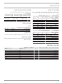
5. Dépannage
Problème Cause Remède
L’appareil ne démarre
pas bien que le robinet
d’eau chaude soit entiè-
rement ouvert.
L’appareil n’est pas sous
tension.
Contrôlez les disjoncteurs
de l’installation domes-
tique.
Le mousseur placé dans
la robinetterie ou la
pomme de douche sont
entartrés ou encrassés.
Nettoyez et/ou détar-
trez le mousseur ou la
pomme de douche.
L’alimentation en eau est
coupée.
Purgez l’appareil et l’ar-
rivée d’eau froide (voir le
chapitre «Installation/
Mise en service/ Pre-
mière mise en service»).
De l’eau froide s’écoule
temporairement pendant
le soutirage d’eau chaude
sanitaire.
Le détecteur d’air trouve
de l’air dans l’eau. Il
coupe brièvement la
puissance de chauffe.
Après 1minute, l’appa-
reil se remet automati-
quement en marche.
Des bruits d’ébullition se
produisent en cours de
fonctionnement.
L’appareil n’est pas
purgé.
Purgez l’appareil (voir le
chapitre «Installation/
Mise en service/ Pre-
mière mise en service»).
La pression d’alimenta-
tion est trop faible.
Assurez-vous que la
pression d’alimentation
minimum est atteinte
(voir le chapitre «Ins-
tallation/ Données
techniques/ Tableau de
données»).
Appelez votre installateur si vous ne réussissez pas à résoudre
le problème. Pour obtenir une aide efficace et rapide, communi-
quez-lui le numéro indiqué sur la plaque signalétique (000000-
0000-000000).
Nr.: 000000-0000-00000
D0000073621
La page est en cours de chargement...
La page est en cours de chargement...
La page est en cours de chargement...
La page est en cours de chargement...
La page est en cours de chargement...
La page est en cours de chargement...
La page est en cours de chargement...
La page est en cours de chargement...
La page est en cours de chargement...
La page est en cours de chargement...
La page est en cours de chargement...
La page est en cours de chargement...
La page est en cours de chargement...
La page est en cours de chargement...
La page est en cours de chargement...
La page est en cours de chargement...
La page est en cours de chargement...
La page est en cours de chargement...
La page est en cours de chargement...
La page est en cours de chargement...
La page est en cours de chargement...
La page est en cours de chargement...
La page est en cours de chargement...
La page est en cours de chargement...
La page est en cours de chargement...
La page est en cours de chargement...
La page est en cours de chargement...
La page est en cours de chargement...
La page est en cours de chargement...
La page est en cours de chargement...
La page est en cours de chargement...
La page est en cours de chargement...
La page est en cours de chargement...
La page est en cours de chargement...
La page est en cours de chargement...
La page est en cours de chargement...
La page est en cours de chargement...
La page est en cours de chargement...
La page est en cours de chargement...
La page est en cours de chargement...
La page est en cours de chargement...
La page est en cours de chargement...
La page est en cours de chargement...
La page est en cours de chargement...
La page est en cours de chargement...
La page est en cours de chargement...
La page est en cours de chargement...
La page est en cours de chargement...
La page est en cours de chargement...
La page est en cours de chargement...
La page est en cours de chargement...
La page est en cours de chargement...
La page est en cours de chargement...
La page est en cours de chargement...
La page est en cours de chargement...
La page est en cours de chargement...
La page est en cours de chargement...
La page est en cours de chargement...
La page est en cours de chargement...
La page est en cours de chargement...
La page est en cours de chargement...
La page est en cours de chargement...
La page est en cours de chargement...
La page est en cours de chargement...
La page est en cours de chargement...
La page est en cours de chargement...
La page est en cours de chargement...
La page est en cours de chargement...
La page est en cours de chargement...
La page est en cours de chargement...
La page est en cours de chargement...
La page est en cours de chargement...
La page est en cours de chargement...
La page est en cours de chargement...
La page est en cours de chargement...
La page est en cours de chargement...
La page est en cours de chargement...
La page est en cours de chargement...
La page est en cours de chargement...
La page est en cours de chargement...
La page est en cours de chargement...
La page est en cours de chargement...
La page est en cours de chargement...
La page est en cours de chargement...
La page est en cours de chargement...
La page est en cours de chargement...
La page est en cours de chargement...
La page est en cours de chargement...
La page est en cours de chargement...
La page est en cours de chargement...
La page est en cours de chargement...
La page est en cours de chargement...
La page est en cours de chargement...
La page est en cours de chargement...
La page est en cours de chargement...
La page est en cours de chargement...
La page est en cours de chargement...
La page est en cours de chargement...
La page est en cours de chargement...
La page est en cours de chargement...
La page est en cours de chargement...
La page est en cours de chargement...
La page est en cours de chargement...
La page est en cours de chargement...
-
 1
1
-
 2
2
-
 3
3
-
 4
4
-
 5
5
-
 6
6
-
 7
7
-
 8
8
-
 9
9
-
 10
10
-
 11
11
-
 12
12
-
 13
13
-
 14
14
-
 15
15
-
 16
16
-
 17
17
-
 18
18
-
 19
19
-
 20
20
-
 21
21
-
 22
22
-
 23
23
-
 24
24
-
 25
25
-
 26
26
-
 27
27
-
 28
28
-
 29
29
-
 30
30
-
 31
31
-
 32
32
-
 33
33
-
 34
34
-
 35
35
-
 36
36
-
 37
37
-
 38
38
-
 39
39
-
 40
40
-
 41
41
-
 42
42
-
 43
43
-
 44
44
-
 45
45
-
 46
46
-
 47
47
-
 48
48
-
 49
49
-
 50
50
-
 51
51
-
 52
52
-
 53
53
-
 54
54
-
 55
55
-
 56
56
-
 57
57
-
 58
58
-
 59
59
-
 60
60
-
 61
61
-
 62
62
-
 63
63
-
 64
64
-
 65
65
-
 66
66
-
 67
67
-
 68
68
-
 69
69
-
 70
70
-
 71
71
-
 72
72
-
 73
73
-
 74
74
-
 75
75
-
 76
76
-
 77
77
-
 78
78
-
 79
79
-
 80
80
-
 81
81
-
 82
82
-
 83
83
-
 84
84
-
 85
85
-
 86
86
-
 87
87
-
 88
88
-
 89
89
-
 90
90
-
 91
91
-
 92
92
-
 93
93
-
 94
94
-
 95
95
-
 96
96
-
 97
97
-
 98
98
-
 99
99
-
 100
100
-
 101
101
-
 102
102
-
 103
103
-
 104
104
-
 105
105
-
 106
106
-
 107
107
-
 108
108
-
 109
109
-
 110
110
-
 111
111
-
 112
112
-
 113
113
-
 114
114
-
 115
115
-
 116
116
-
 117
117
-
 118
118
-
 119
119
-
 120
120
-
 121
121
-
 122
122
-
 123
123
-
 124
124


STIEBEL ELTRON DCE-C 6-12 Trend Operation Instruction
- Taper
- Operation Instruction
Documents connexes
-
STIEBEL ELTRON DCE-C 6/8 Trend Operation Instruction
-
-
-
-
-
-
-
STIEBEL ELTRON DEL 18-27 Plus Operation Instruction
-
-