
Turbine Flow Meter
Top Load 1 in. and 2 in. Meters
TRB-UM-02597-EN-01 (September 2018)
User Manual

CONTENTS
Unpacking and Inspection � � � � � � � � � � � � � � � � � � � � � � � � � � � � � � � � � � � � � � � � � 3
Introduction� � � � � � � � � � � � � � � � � � � � � � � � � � � � � � � � � � � � � � � � � � � � � � � � � � � 3
Operating Principle � � � � � � � � � � � � � � � � � � � � � � � � � � � � � � � � � � � � � � � � � � � � � � 3
Preinstallation Considerations � � � � � � � � � � � � � � � � � � � � � � � � � � � � � � � � � � � � � � � 4
Installation� � � � � � � � � � � � � � � � � � � � � � � � � � � � � � � � � � � � � � � � � � � � � � � � � � � � 5
Pressure Drop Chart� � � � � � � � � � � � � � � � � � � � � � � � � � � � � � � � � � � � � � � � � � � � � � 7
Operational Startup � � � � � � � � � � � � � � � � � � � � � � � � � � � � � � � � � � � � � � � � � � � � � � 7
Turbine Assembly Replacement � � � � � � � � � � � � � � � � � � � � � � � � � � � � � � � � � � � � � � 8
Turbine Assembly Repair Kit Part Number� � � � � � � � � � � � � � � � � � � � � � � � � � � � � 8
Turbine Assembly Replacement Procedure � � � � � � � � � � � � � � � � � � � � � � � � � � � � 8
Specications � � � � � � � � � � � � � � � � � � � � � � � � � � � � � � � � � � � � � � � � � � � � � � � � � 10
Part Number Information � � � � � � � � � � � � � � � � � � � � � � � � � � � � � � � � � � � � � � � � � 10
Troubleshooting Guide� � � � � � � � � � � � � � � � � � � � � � � � � � � � � � � � � � � � � � � � � � � 11
Turbine Flow Meter, Top Load 1 in. and 2 in. Meters
Page ii September 2018TRB-UM-02597-EN-01

Unpacking and Inspection
Page 3 September 2018 TRB-UM-02597-EN-01
UNPACKING AND INSPECTION
Upon opening the shipping container, visually inspect the product and applicable
accessories for any physical damage such as scratches, loose or broken parts, or any other
sign of damage that may have occurred during shipment�
OTE:N If damage is found, request an inspection by the carrier’s agent within 48 hours of
delivery and file a claim with the carrier� A claim for equipment damage in transit is
the sole responsibility of the purchaser�
INTRODUCTION
Designed to withstand the demands of the most rigorous flow measurement applications,
the Top Load Turbine Flow Meter is reliable, rugged and cost effective� Originally developed
for the secondary oil recovery market, the Top Load Turbine Flow Meter is an ideal meter for
liquid flow measurement on or off the oil field�
The meter features a rugged 316 stainless steel housing, rotor shaft, and rotor support
assemblies, a Buna-N O-ring, C17-4PH stainless steel rotor, and hybrid ceramic ball bearings
with AMS 5898 duplex stainless steel race and stainless steel retainer�
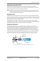
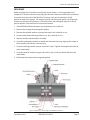
OPERATING PRINCIPLE
Fluid entering the meter passes through the inlet flow straightener which reduces its
turbulent flow pattern and improves the fluid’s velocity profile� Fluid then passes through
the turbine, causing it to rotate at a speed proportional to the fluid velocity� As each
turbine blade passes through the magnetic field, the blade generates an AC voltage pulse
in the pickup coil at the base of the magnetic pickup (see Figure 1)� These pulses produce
an output frequency proportional to the volumetric flow through the meter� The output
frequency represents flow rate and/or totalization of fluid passing through the meter�
Turbine Rotor
Magnetic Pickup
or
Other Frequency
Output Device
Output
Signal
Figure 1: Schematic illustration of electric signal generated by rotor movement

Preinstallation Considerations
Page 4 September 2018TRB-UM-02597-EN-01
PREINSTALLATION CONSIDERATIONS
All Badger Meter® Top Load Turbine Flow Meters use stainless steel construction materials�
Make sure the operating fluid is compatible with these materials� Incompatible fluids can
cause deterioration of internal components and cause a reduction in meter accuracy�
The measured liquid should be free of any large particles that may inhibit rotation of the
turbine blades� If particles are present, install a mesh strainer upstream before operating
the meter� See Table 1 for strainer recommendations�
Part Number Strainer Mesh Clearance Filter Size
B411-110 60 0�0092 in� 260 μm
B411-120 10 0�0650 in� 1�6 mm
Table 1: Strainer mesh installation details
The preferred plumbing setup is one containing a bypass line (see Figure 2 on page 6)
that allows meter inspection and repair without interrupting flow� If a bypass line is not
used, it is important that all control valves be located downstream of the flow meter (see
Figure 3 on page 6)�
STRIKING AN EMPTY METER WITH HIGH VELOCITY FLOW STREAM CAN
CAUSE DAMAGE.
ATTENTION
DES DOMMAGES PEUVENT ÊTRE PROVOQUÉS EN FRAPPANT UN MÈTRE VIDE AVEC UN
JET D’ÉCOULEMENT DE VITESSE ÉLEVÉE.
Remove any restriction in the flow line that may cause the liquid to flash� If necessary, install
air eliminators so the meter is not incorrectly measuring entrained air or gas�
Badger Meter recommends installation of a minimum length, equal to ten (10) pipe
diameters of straight pipe on the upstream side and five (5) diameters on the downstream
side of the flow meter� Otherwise meter accuracy may be affected� Piping should be the
same size as the meter bore or threaded port size�
Severe pulsation and mechanical vibration affect accuracy and shorten the life of the
meter� If this condition is present, consider using a meter possessing superior resistance to
pulsation and vibration like the Badger Meter QuikSert Inline Flow Meter� Do not locate the
meter or connection cable close to electric motors, transformers, sparking devices, high
voltage lines, or place connecting cable in conduit with wires furnishing power for such
devices� These devices can induce false signals in the meter coil or cable, causing the meter
to read inaccurately�
If problems arise with the meter, consult the "Troubleshooting Guide" on page 11� If further
problems arise, consult the factory�
If the internal components of the meter are damaged, replace them with a turbine meter
repair kit available from Badger Meter� For information pertaining to the repair kits, see
"Turbine Assembly Replacement" on page 8�

Installation
Page 5 September 2018 TRB-UM-02597-EN-01
INSTALLATION
PRESSURE IN EXCESS OF ALLOWABLE RATING MAY CAUSE THE HOUSING TO BURST
AND CAUSE SERIOUS PERSONAL INJURY.
AVERTISSEMENT
LA PRESSION AU-DESSUS DE L’ESTIMATION PERMISE PEUT FAIRE ÉCLATER ET CAUSER
LE LOGEMENT LE DOMMAGE CORPOREL SÉRIEUX.
1� Check the inside of the ow meter for any foreign material� Make sure the turbine rotor
spins freely prior to installation� Also, check uid lines and remove any debris found�
2� Install the ow meter with the ow arrow, etched onto the exterior of the meter body,
pointing in the direction of uid ow� Though the meter is designed to function in any
position, where possible, install it horizontally with the conduit adapter facing upward�
3� Thread a magnetic pickup into the conduit adapter completely, nger tight without
forcing it�
4� Install conduit or other ttings suitable for the installation area onto the conduit
adapter hub on the ow meter�

Installation
Page 6 September 2018TRB-UM-02597-EN-01
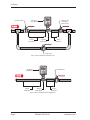
Bypass Valve
Isolation Valve
Isolation and
Flow Rate
Control Valve
5 Pipe
Diameters
Turbine
Flow Meter
10 Pipe
Diameters
Electronic
Flow Monitor
Figure 2: Meter installation with a bypass line
Electronic
Flow Monitor
Control Valve
5 Pipe
Diameters
Turbine
Flow Meter
10 Pipe
Diameters
Figure 3: Meter installation without a bypass line

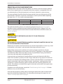
Pressure Drop Chart
Page 7 September 2018 TRB-UM-02597-EN-01
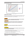
PRESSURE DROP CHART
QCM0200
QCM0100
Flow Rate (gpm)
Pressure Drop (psi)
2
1
0
3
4
5
0 50 100 150 200 250
6
7
B411-110
B411-120
Figure 4: Pressure drop
OPERATIONAL STARTUP
Follow these steps when installing and starting the meter� After meter installation, close the
isolation valves and open the bypass valve� Allow liquid to flow through the bypass valve
for sufficient time to eliminate any air or gas in the flow line�
MAKE SURE TO SHUT OFF FLUID FLOW AND RELEASE PRESSURE IN THE LINE BEFORE
ATTEMPTING TO INSTALL THE METER IN AN EXISTING SYSTEM.
AVERTISSEMENT
ASSUREZ-VOUS QUE LE FLUX DE FLUIDE A ÉTÉ COUPÉ ET DE LA PRESSION DANS
LA LIGNE A ÉTÉ LIBÉRÉE AVANT D’ESSAYER D’INSTALLER LE MÈTRE DANS UN
SYSTÈME ACTUEL.
HIGH VELOCITY AIR OR GAS MAY DAMAGE THE INTERNAL COMPONENTS OF
THE METER.
ATTENTION
DES DOMMAGES PEUVENT ÊTRE PROVOQUÉS EN FRAPPANT UN MÈTRE VIDE AVEC UN
JET D’ÉCOULEMENT DE VITESSE ÉLEVÉE.
1� Open the upstream isolating valve slowly to eliminate hydraulic shock while charging
the meter with the liquid� Open the valve to full open�
2� Open the downstream isolating valve to permit the meter to operate�
3� Close the bypass valve to a fully closed position�
4� Adjust the downstream valve to provide the required ow rate through the meter�
OTE:N If necessary, use the downstream valve as a control valve�

Turbine Assembly Replacement
Page 8 September 2018TRB-UM-02597-EN-01
TURBINE ASSEMBLY REPLACEMENT
The meter uses wear-resistant moving parts to provide trouble-free operation and long
service life� Designed for easy field service of a damaged turbine assembly, the repair kits
replace only the internal parts, rather than replacing the entire meter� The turbine assembly
uses stainless steel alloy construction materials�
Each repair kit assembly is factory calibrated to provide accuracy throughout the entire
flow range� Each kit is complete and includes a new K-factor, which is the calibrated
number of pulses generated by each gallon of liquid� Recalibration of the monitor or other
electronics use the K-factor to provide accurate output data�
Turbine Assembly Repair Kit Part Number
Meter Size
Repair Kit Fits
Meter Part Number
Repair Kit Part Number
1 in� B411-110 B411005
2 in� B411-120 B411006
Table 2: Repair kits
For 1 in.
Meter
B411-110
For 2 in.
Meter
B411-120
Description
Repair Part Number
B251-610 B251-620 Complete turbine assembly replacement kit, with magnetic pickup
B251-611 B251-621 Turbine assembly replacement kit, without pickup
B411005 B411006 Insert, with pickup
B411026 B411027 Insert, without pickup
B411007 B411008 External retainer ring
B411003 B411004 Retainer nut
B251-610 TI B251-620 TI Turbine assembly replacement kit for TI meters
Table 3: Turbine assembly repair kit components
Turbine Assembly Replacement Procedure
HIGH-PRESSURE LEAKS ARE DANGEROUS AND MAY CAUSE PERSONAL INJURY. MAKE
SURE TO SHUT OFF FLUID FLOW AND RELEASE RESIDUAL PRESSURE IN THE LINE
BEFORE ATTEMPTING TO REMOVE THE METER.
AVERTISSEMENT
LES FUITES À HAUTE PRESSION SONT DANGEREUSES ET PEUVENT CAUSER LE
DOMMAGE CORPOREL. ASSUREZ-VOUS QUE LE FLUX DE FLUIDE A ÉTÉ COUPÉ ET DE LA
PRESSION DANS LA LIGNE A ÉTÉ LIBÉRÉE AVANT D’ESSAYER D’ENLEVER LE MÈTRE.

Turbine Assembly Replacement
Page 9 September 2018 TRB-UM-02597-EN-01
MPORTANTI
Before installing the new turbine assembly, note that an arrow is cast or engraved on each
component. The arrow indicates the primary flow direction. When reassembled, the arrowheads
must point in the direction of the fluid flow. The arrows must also be oriented in the UP
position on both rotor supports. The magnetic pickup side of the body signifies the UP position.
Performance of repair kit calibration is in the UP position. Reinstalling the repair kit in the UP
position provides continuation of accurate measurements.
1� Shut o the uid ow and release any residual pressure in the line�
2� Remove the wiring from the magnetic pickup�
3� Remove the external retainer ring from the meter� Set it aside for re-use�
4� Unscrew and remove the large retainer nut� Set it aside for re-use�
5� Remove and discard the turbine assembly�
6� Insert the replacement turbine assembly into the meter housing, aligning the cutout in
the assembly with the key in the housing�
7� Screw on the large retainer nut you set aside in step 4� Tighten it enough to clear the lip
in the meter body�
8� Insert the external retainer ring you set aside in step 3� It ts just below the lip in the
meter body�
9� Reconnect the monitor to the magnetic pickup�
Figure 5: Typical cross-section of B411-110 and B411-120 meters

Specications
Page 10 September 2018TRB-UM-02597-EN-01
SPECIFICATIONS
Materials of
Construction
Body 316 stainless steel
Rotor C17-4PH stainless steel
Bearing
Hybrid ceramic ball bearing with AMS 5898 duplex
stainless steel race and stainless steel retainer
Rotor Shaft 316 stainless steel
Rotor Support 316 stainless steel
O-Ring Buna-N
Operating Temperature –150…350° F (–101…177° C)
Pressure Rating 1500 psi max�
End Connections NPT
Turndown Ratio 15:1
Flow Accuracy ±1% of reading
Repeatability ±0�1%
Calibration Water (NIST traceable calibration)
Pickup B111129
Certifications —
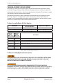
PART NUMBER INFORMATION
1
Part
Number
Bore Size End
Connections
Max.
PSI
Flow Ranges
Strainer
Mesh
Approx.
K-factor
Pulse/Gal
Meter
Weight
(lb)
End to End
Length
B411-110
1 in�
(25�4 mm)
1 in� male NPT 1500
See “Flow Ranges”
40 870 2
6 in�
(152�4 mm)
B411-120
2 in�
(50�8 mm)
2 in� male NPT 1500 20 52 14
6 in�
(152�4 mm)
1
Includes Standard Mag Pickup, p/n B111129, -150…330° F (-101…165° C), suitable for all mounting styles
Flow Ranges
Part Number
Flow Ranges
gpm (lpm) bpd m3/d
B411-110 5…75 (18�9…283�91) 171�43…2571�43 27�26…408�82
B411-120 15…225 (56�78…851�72) 514�29…7714�29 81�76…1226�47

Troubleshooting Guide
Page 11 September 2018 TRB-UM-02597-EN-01
TROUBLESHOOTING GUIDE
Issue Possible Cause Remedy
Meter indicates higher than
actual flow rate�
Cavitation�
Debris on rotor support�
Build up of foreign material on
meter bore�
Gas in liquid�
Increase back pressure�
Clean meter�
Clean meter�
Install gas eliminator ahead
of meter�
Meter indicates lower than
actual flow rate�
Debris on rotor�
Worn bearing�
Viscosity higher than calibrated�
Clean meter and add filter�
Clean meter and add filter�
Recalibrate monitor�
Erratic system indication, meter
alone works well (remote
monitor application only)�
Ground loop in shielding� Ground shield one place only�
Look for internal electronic
instrument ground� Reroute
cables away from
electrical noise�
Indicator shows flow when
shut off�
Mechanical vibration causes
rotor to oscillate
without turning�
Isolate meter�
No flow indication�
Full or partial open position�
Fluid shock, full flow into dry
meter or impact caused bearing
separation or broken rotor shaft�
Rebuild meter with repair kit
and recalibrate monitor� Move to
location where meter is full on
startup or add downstream flow
control valve�
Erratic indication at low flow,
good indication at high flow�
Rotor has foreign material
wrapped around it�
Clean meter and add filter�
No flow indication� Faulty pickup� Replace pickup�
System works perfect, except
indicates lower flow over
entire range�
By-pass flow, leak� Repair or replace bypass valves,
or faulty solenoid valves�
Meter indicating high flow,
upstream piping at meter
smaller than meter bore�
Fluid jet impingement on rotor� Change piping�
Meter indicating low flow,
upstream piping at meter
smaller than meter bore�
Viscosity lower than calibrated� Change temperature, change
fluid or recalibrate meter�

Turbine Flow Meter, Top Load 1 in. and 2 in. Meters
www.badgermeter.com
BLANCETT is a registered trademark of Badger Meter, Inc� Other trademarks appearing in this document are the property of their respective entities� Due to
continuous research, product improvements and enhancements, Badger Meter reserves the right to change product or system specications without notice, except
to the extent an outstanding contractual obligation exists� © 2018 Badger Meter, Inc� All rights reserved�
Control. Manage. Optimize.
The Americas | Badger Meter | 4545 West Brown Deer Rd | PO Box 245036 | Milwaukee, WI 53224-9536 | 800-876-3837 | 414-355-0400
México | Badger Meter de las Americas, S.A. de C.V. | Pedro Luis Ogazón N°32 | Esq� Angelina N°24 | Colonia Guadalupe Inn | CP 01050 | México, DF | México | +52-55-5662-0882
Europe, Eastern Europe Branch Oce (for Poland, Latvia, Lithuania, Estonia, Ukraine, Belarus) | Badger Meter Europe | ul� Korfantego 6 | 44-193 Knurów | Poland | +48-32-236-8787
Europe, Middle East and Africa | Badger Meter Europa GmbH | Nurtinger Str 76 | 72639 Neuen | Germany | +49-7025-9208-0
Europe, Middle East Branch Oce | Badger Meter Europe | PO Box 341442 | Dubai Silicon Oasis, Head Quarter Building, Wing C, Oce #C209 | Dubai / UAE | +971-4-371 2503
Slovakia | Badger Meter Slovakia s.r.o. | Racianska 109/B | 831 02 Bratislava, Slovakia | +421-2-44 63 83 01
Asia Pacic | Badger Meter | 80 Marine Parade Rd | 21-06 Parkway Parade | Singapore 449269 | +65-63464836
Switzerland | Badger Meter Swiss AG | Mittelholzerstrasse 8 | 3006 Bern | Switzerland | +41-31-932 01 11
-
 1
1
-
 2
2
-
 3
3
-
 4
4
-
 5
5
-
 6
6
-
 7
7
-
 8
8
-
 9
9
-
 10
10
-
 11
11
-
 12
12


Badger Meter Blancett B411-110 Manuel utilisateur
- Taper
- Manuel utilisateur
- Ce manuel convient également à
dans d''autres langues
Documents connexes
Autres documents
-
Sames Turbine speed control Manuel utilisateur
-
Omega FTB690 and FTB690-P Series Le manuel du propriétaire
-
-
-
-
3M 5621102 Mode d'emploi
-
DYNACORD 4120 Manuel utilisateur
-
3M 7100007699 Manuel utilisateur
-
 Fill-rite TT10PN Mode d'emploi
