Intermec MobileLAN access Manuel utilisateur
- Taper
- Manuel utilisateur

MobileLAN™power
User's Guide

ii MobileLAN power User’s Guide
Intermec Technologies Corporation
6001 36 Avenue West
Everett, WA 98203
U.S.A.
U.S. service and technical support: 1-800-755-5505
U.S. media supplies ordering information: 1-800-227-9947
Canadian service and technical support: 1-800-668-7043
Canadian media supplies ordering information: 1-800-268-6936
Outside U.S.A. and Canada: Contact your local Intermec service
supplier.
The information contained herein is proprietary and is provided
solely for the purpose of allowing customers to operate and/or
service Intermec manufactured equipment and is not to be released,
reproduced, or used for any other purpose without written
permission of Intermec.
Information and specifications in this manual are subject to change
without notice.
©2003 by Intermec Technologies Corporation
All Rights Reserved
The word Intermec, the Intermec logo, INCA (under license),
MobileLAN, JANUS, IRL, Trakker Antares, EZBuilder, TE 2000,
Data Collection Browser, dcBrowser, Data Collection PC,
Universal Access Point, UAP, Duratherm, EasyCoder, Precision
Print, PrintSet, Virtual Wedge, and CrossBar are either trademarks
or registered trademarks of Intermec.
Throughout this manual, trademarked names may be used. Rather
than put a trademark (™ or ®) symbol in every occurrence of a
trademark name, we state that we are using the names only in an
editorial fashion, and to the benefit of the trademark owner, with
no intention of infringement.
There are U.S. and foreign patents pending

MobileLAN power User’s Guide iii
Manual Change Record
This page records the changes to this document. The manual was
originally released as version 001.
Version Date Description of Change
002 03/03 Updated information to remove references to the Power
Not Active LED. Made other small changes.

iv MobileLAN power User’s Guide

Contents
v MobileLAN power User’s Guide
Contents
Before You Begin.................................................................... vii
Warranty Information .............................................. vii
Safety Summary ....................................................... vii
Warnings, Cautions, and Notes............................... viii
About this Guide....................................................... ix
Introduction........................................................................... 1
About the Power Bridge............................................................ 2
Power Bridge—Front View Detail ............................................ 3
Power Bridge—Rear View Detail.............................................. 4
Power Bridge Status LEDs........................................................ 5
Powering Ethernet Devices ....................................................... 6
Installing the Power Bridge ....................................... 7
Verifying Kit Contents .............................................................8
Recording Identification Information ....................................... 8
Choosing a Suitable Site ........................................................... 8
Mounting the Power Bridge...................................................... 9
Free-Stand Mounting ................................................. 9
Wall Hanging............................................................. 9
Cabling the Power Bridge ....................................................... 10
Connecting Cables to the Power Bridge.................... 11
Connecting Cables to End Devices...........................11
1
2

Contents
vi MobileLAN power User’s Guide
Safety Information ......................................................... 15
Important Safety Information................................................. 16
Power Cord Set...................................................................... 18
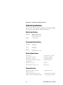
Specifications and Troubleshooting................ 19
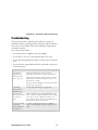
Technical Specifications ......................................................... 20
Physical Specifications.............................................. 20
Environmental Specifications ................................... 20
Electrical Specifications............................................ 20
Ethernet Interface .................................................... 20
Troubleshooting..................................................................... 21
A
B

Before You Begin
MobileLAN power User’s Guide vii
Before You Begin
This section introduces you to standard warranty provisions, safety
precautions, and about this guide.
Warranty Information
To receive a copy of the standard warranty provision for this
product, contact your local Intermec sales organization. In the
U.S., call 1-800-755-5505, in Canada, call 1-800-668-7043.
Note: Opening this product may void the warranty. The
internal workings of this product can only be accessed by
Intermec service personnel. Radio replacements and
upgrades require Intermec service personnel.
Safety Summary
Your safety is extremely important. Read and follow all warnings
and cautions in this book before handling and operating Intermec
equipment. You can be seriously injured, and equipment and data
can be damaged if you do not follow the safety warnings and
cautions.
Do not repair or adjust alone
Do not repair or adjust energized equipment alone under any
circumstances. Someone capable of providing first aid must always
be present for your safety.
First aid
Always obtain first aid or medical attention immediately after an
injury. Never neglect an injury, no matter how slight it seems.
Resuscitation
Begin resuscitation immediately if someone is injured and stops
breathing. Any delay could result in death. To work on or near
high voltage, you should be familiar with approved industrial first
aid methods.

Before You Begin
viii MobileLAN power User’s Guide
Energized Equipment
Never work on energized equipment unless authorized by a
responsible authority. Energized electrical equipment is dangerous.
Electrical shock from energized equipment can cause death. If you
must perform authorized emergency work on energized equipment,
be sure that you comply strictly with approved safety regulations.
Warnings, Cautions, and Notes
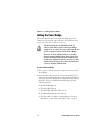
A warning contains directions that must be followed
for personal and product safety. Follow all
directions carefully.
Avertissement: Les avertissements comprennent des
instructions qui doivent être respectées pour assurer
la sécurité des personnes et de l’équipement.
Respectez scrupuleusement toutes les instructions.
A caution alerts you to an operating procedure,
practice, condition, or statement that must be
strictly observed to prevent equipment damage or
destruction, or corruption or loss of data.
Attention: Une précaution vous avertit d’une
procédure de fonctionnement, d’une méthode, d’un
état ou d’un rapport qui doit être strictement
respecté pour empêcher l’endommagement ou la
destruction de l’équipement, ou l’altération ou la
perte de données.
Note: Notes either provide extra information about a
topic or contain special instructions for handling a
particular condition or set of circumstances.

Before You Begin
MobileLAN power User’s Guide
ix
About this Guide
This document provides information and procedures regarding
installation, configuration, and management of the
MobileLAN™power bridge.
Prerequisite Skills and Knowledge
This guide is intended for use by network administrators who are
responsible for installing network equipment; consequently, it
assumes a basic working knowledge of LANs (Local Area
Networks).
To use this document effectively, you should have a working
knowledge of Ethernet infrastructures. In addition, you should
have a working knowledge of
• basic electronics and mechanical assembly, as well as an
understanding of related local building codes.
• local operating and troubleshooting procedures.

Before You Begin
x MobileLAN power User’s Guide

MobileLAN power User’s Guide 1
Introduction
This chapter introduces the MobileLAN™power
bridge and explains how it can be used in your
network. This chapter covers these topics:
• About the Power Bridge
• Power Bridge—front view detail
• Power Bridge status indications
• Power Bridge—rear view detail
• Powering Ethernet devices
1

Chapter 1 — Introduction
2 MobileLAN power User’s Guide
About the Power Bridge
The Power Bridge is a single Ethernet channel power-feeding
device. It is designed for use with a 10BaseT/100BaseTx standard
Ethernet network over a standard TIA/EIA-568 Category 5 (or
higher) cabling plant. The DC operating power for the data
terminal units is fed through the unused pairs (7/8 and 4/5).
The Power Bridge normally powers devices that are Power over
Ethernet Enabled; that is, they are equipped to receive power over
Ethernet. Devices that are not equipped to receive power over
Ethernet can be powered by the Power Bridge, but they require an
external splitter.
The Power Bridge has the following features:
• Remote power feeding of Ethernet terminals
• A single 10BaseT/100BaseTx data + power combined channel
• Universal 90 to 264 VAC, 50 to 60 Hz power input
• Port overload and short-circuit protection
• Port status LEDs
• 15.4W minimum allowable output power
• Free-standing or wall-hanging mounting
The Power Bridge also eliminates the need for terminal’s AC
outlets, UPS, and AC/DC adapters.

Chapter 1 — Introduction
MobileLAN power User’s Guide 3
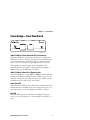
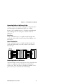
Power Bridge—Front View Detail
MLP001.eps
10BaseT/100BaseTx Power & Data Out Port, Left Connector
The Power Bridge has a single Power & Data port configured as
MDI (non-crossover). This port is designed to carry Ethernet data
over the standard 2-wire pairs (RJ-45 pins 1/2 and 3/6) and DC
power source over the spare wire pair (RJ-45 pins 4/5 and 7/8).
The maximum segment length from the switch/hub to the
Network Interface Card (NIC), including the Power Bridge, is
100m (328 ft), per the IEEE 802.3 standard.
10BaseT/100BaseTx Data In Port, Right Connector
The Power Bridge has a single 10BaseT/100BaseTx data input port
configured as Media Dependant Interface (MDI) (non-crossover).
This port is designed to carry Ethernet data only (Tx/Rx) over the
standard 2-wire pairs (RJ-45 pins 1/2 and 3/6).
Power Active LED
The Power Active LED (green) indicates the terminal unit has been
identified as Power Enabled and is active and receiving power. For
more information, see “Power Bridge Status LEDs” on page 5.
Main LED
The Main LED (green) provides the Power Bridge’s AC power
status. For more information, see “Power Bridge Status LEDs” on
page 5.

Chapter 1 — Introduction
4 MobileLAN power User’s Guide
Power Bridge—Rear View Detail
Vac
100-240 60/50 0.34-0.17
Hz A
Caution: Shock Potential
Disconnect the Power
Before Servicing.
MLP002.eps
AC Power Receptacle
Electrocution Hazard. Before connecting power to
the Power Bridge, please refer to the safety
information in Appendix A.
Avertissement: Risque d’électrocution. Avant de
connecter l’alimentation au Pont d’alimentation,
veuillez consulter les informations relatives à la
sécurité à l’annexe A.
The Power Bridge automatically adjusts its power setting to any
supply voltage from 90 to 240 VAC.
See Appendix A for proper selection of a power cord.
Supply Data Label
The Supply Data label contains information regarding the total AC
power input (100 to 240 VAC), power frequency (60/50 Hz), and
the corresponding amperes.
See Appendix A for proper selection of a power cord.
Information Label
The Information label (located on the bottom of the Power Bridge)
shows the following:
• Part number of the Power Bridge
• Serial number of the Power Bridge and date code
• Electrical and safety compliance
You may need this information for reporting purposes.

Chapter 1 — Introduction
MobileLAN power User’s Guide 5
Power Bridge Status LEDs
These tables contain Power Bridge status information as presented
by the front panel LEDs during normal operation.
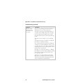
Power Active LED Table
Power Active
LED Status
Port Load Conditions
Port Voltage
Off Non-active load or unplugged
port
No DC voltage is present
over the wires
On Active load is plugged in and
complies with normal load
conditions
Continuous nominal DC
voltage is present on the
spare pairs
Blinking Overload conditions or shorted
terminal port or forced
external voltage feed (constant
DC) into the port
Power to the port is
disconnected
No DC voltage is present
on the spare pairs
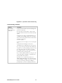
Main LED Table
Main LED
Status
Main Power Status
Remarks
Off Main internal power supply
unit is unplugged or faulty
AC input is not active
On Main power supply unit is
plugged in and under normal
operating conditions
Main voltage is 44V to
57V
Blinking and
Power Active
LED off
Main power supply unit
voltage exceeds specified limits
Main voltage is under 46V
or above 57V; port’s power
is disabled
For more information on using the LEDs to troubleshoot, see
Appendix B, “Specifications and Troubleshooting.”

Chapter 1 — Introduction
6 MobileLAN power User’s Guide
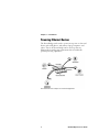
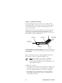
Powering Ethernet Devices
The Power Bridge can be used to power access points or other end
devices such as IP phones, web cameras, laptop computers, and
others. That is, the Power Bridge can be used to power any
Ethernet device with power requirements that are within the
specified powering capabilities.
This illustration shows examples of network configurations.

MobileLAN power User’s Guide 7
Installing the Power
Bridge
This chapter contains information needed to
install the Power Bridge. This chapter covers these
topics:
• Verifying kit contents
• Recording identification information
• Choosing a suitable site
• Mounting the Power Bridge
• Powering up the Power Bridge
• Cabling the Power Bridge
2

Chapter 2 — Installing the Power Bridge
8 MobileLAN power User’s Guide
Verifying Kit Contents
Unpack the kit and verify that these items are present:
• Power Bridge
• Rubber feet
• User’s guide (this manual)
Recording Identification Information
Before proceeding with the Power Bridge placement and
installation, record the serial number here for future reference. The
serial number is located on the Information label on the bottom of
the Power Bridge.
Serial Number
Choosing a Suitable Site
Read the safety information provided in Appendix A
before carrying out any installation, removal, or any
maintenance procedure on the Power Bridge.
Avertissement: Vous devez lire toutes les
informations concernant la sécurité à l’annexe A
avant d’entreprendre l’installation, le retrait ou toute
procédure d’entretien du Pont d’alimentation.
The Power Bridge is suited for use in an office environment where
it can stand alone (free stand) or hang from a wall.
When deciding where to position the Power Bridge, be sure that
• the Power Bridge is accessible and cables can be connected
easily.
• the ambient room temperature is less than 40°C (104°F);
however, the recommended room temperature is 25°C (77°F) or
less.

Chapter 2 — Installing the Power Bridge
MobileLAN power User’s Guide 9
• airflow is not restricted around the Power Bridge or through the
vents in the side of the Power Bridge. We recommend that you
provide a minimum of 25 mm (1 in) clearance around the two
sides and the back of the Power Bridge, excluding mounting
surfaces.
• water or moisture cannot enter the case of the Power Bridge.
In addition, be sure that cabling is away from
• sources of electrical noise such as radios, transmitters, and
broadband amplifiers.
• power lines and fluorescent lighting fixtures.
Mounting the Power Bridge
Disconnect all cables from the Power Bridge before
continuing.
Attention: Déconnectez tous les câbles du Pont
d’alimentation avant de continuer.
There are two ways that you can mount the Power Bridge:
• Free-stand mounting
• Wall hanging
Free-Stand Mounting
• Place the self-adhesive rubber feet provided in the kit on the
underside of the Power Bridge. Be sure to place the rubber feet
on their markings.
Wall Hanging
1 Drill two 6 mm (.24 in) holes.
2 Insert a screw (not included) in each hole, leaving 0.5 cm (.2 in)
of the screws protruding out of the wall.
3 Hang the Power Bridge on the screws.

Chapter 2 — Installing the Power Bridge
10 MobileLAN power User’s Guide
Cabling the Power Bridge
This section describes how to get the Power Bridge powered on,
connected to the network, and connected to the end device. Once
you get it connected, it is ready for operation.
The Power Bridge has no ON/OFF switch. To
connect or disconnect power to the Power Bridge,
simply insert or remove the power cable from the AC
power receptacle on the rear of the Power Bridge.
Attention: Le Pont d’alimentation n’est pas muni
d’un interrupteur Marche/Arrêt. Pour connecter ou
déconnecter l’alimentation du Pont d’alimentation,
veuillez tout simplement brancher ou retirer le câble
d’alimentation de la prise de courant alternatif située
à l’arrière du Pont d’alimentation.
To power on the Power Bridge
1 Insert a power cord into the power receptacle on the rear of the
Power Bridge.
2 Insert the other end of the power cord into the wall AC power
outlet. The Power Bridge powers up and runs through its Power
On Self Test (POST), which takes less than 10 seconds. During
the POST, the port is disabled and the LEDs light up in the
following sequence:
a The Main LED lights up.
b The Active LED light up.
c The Main LED and Active LED turn off.
d The Main LED lights up and remains lit.
e The Active LED is ready for normal indications. For more
information, see the “Power Active LED Table” on page 5.
La page est en cours de chargement...
La page est en cours de chargement...
La page est en cours de chargement...
La page est en cours de chargement...
La page est en cours de chargement...
La page est en cours de chargement...
La page est en cours de chargement...
La page est en cours de chargement...
La page est en cours de chargement...
La page est en cours de chargement...
La page est en cours de chargement...
La page est en cours de chargement...
La page est en cours de chargement...
La page est en cours de chargement...
-
 1
1
-
 2
2
-
 3
3
-
 4
4
-
 5
5
-
 6
6
-
 7
7
-
 8
8
-
 9
9
-
 10
10
-
 11
11
-
 12
12
-
 13
13
-
 14
14
-
 15
15
-
 16
16
-
 17
17
-
 18
18
-
 19
19
-
 20
20
-
 21
21
-
 22
22
-
 23
23
-
 24
24
-
 25
25
-
 26
26
-
 27
27
-
 28
28
-
 29
29
-
 30
30
-
 31
31
-
 32
32
-
 33
33
-
 34
34


Intermec MobileLAN access Manuel utilisateur
- Taper
- Manuel utilisateur
dans d''autres langues
Documents connexes
-
Intermec MobileLAN power 12 Manuel utilisateur
-
-
-
-
Intermec MobileLAN access WA22 Guide de démarrage rapide
-
Intermec MobileLAN access 2102 Guide de démarrage rapide
-
-
-
Intermec MaxiScan 2100 Guide de démarrage rapide
-