Tripp Lite SU120KX2 3-Phase UPS Manuel utilisateur
- Catégorie
- Alimentations sans interruption (UPS)
- Taper
- Manuel utilisateur
Ce manuel convient également à

1
5
9
3
7
11
2
6
10
4
8
12
13
14
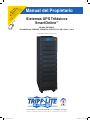
Owner’s Manual
PROTECT
YOUR INVESTMENT!
Completed and signed start-up forms
MUST be submitted and approved
by Tripp Lite to activate your warranty.
1
SmartOnline
™
3-Phase UPS Systems
Model: SU120KX2
Input/Output: 220/380V, 230/400V or 240/415V AC, 3O, 4-wire + ground
Not suitable for mobile applications.
1111 W. 35th Street, Chicago, IL 60609 USA • www.tripplite.com/support
Copyright © 2012 Tripp Lite. All trademarks are the sole property of their respective owners.
12-212-93-3141.indb 1 12/28/2012 11:16:51 AM

1
5
9
3
7
11
2
6
10
4
8
12
13
14
2
Table of Contents
1 Introduction 3
2 Important Safety Instructions 4
3 Control Panel Features 6
4 Front and Rear Panel Features 7
5 Cabinet Installation 9
5-1 Preparation 9
5-2 Unpacking 9
5-3 Placement 10
6 Wiring 11
6-1 Wiring Warnings 11
6-2 Wiring Preparation 11
6-3 UPS System Terminal Block Diagram 12
6-4 External Battery Cabinet Wiring Diagrams 12
6-5 Electrical and Cable Data 13
6-6 External Battery Cabinet Wiring 14
6-7 AC Input/Output Wiring (Single UPS—SUS) 14
6-8 AC Input/Output Wiring (Parallel Configuration—2x MUS) 15
6-9 AC Input/Output Wiring (Parallel Configuration—4x MUS) 16
7 Operating Modes 17
7-1 Online (Normal) Mode (Single UPS—SUS) 17
7-2 Battery Backup Mode (Single UPS—SUS) 17
7-3 Auto Bypass Mode (Single UPS—SUS) 17
7-4 Manual Bypass Mode (Single UPS—SUS) 17
7-5 On-line (Normal) Mode (Parallel UPS—MUS) 18
7-6 Battery Backup Mode (Parallel UPS—MUS) 18
7-7 Auto Bypass Mode (Parallel UPS—MUS) 18
7-8 Manual Bypass Mode (Parallel UPS—MUS) 19
7-9 External Maintenance Bypass (Parallel UPS—MUS) 19
8 Start-Up, Shutdown and Bypass 20
8-1 Control Panel and Breaker Diagrams 20
8-2 Preliminary Checklist (Single UPS—SUS) 20
8-3 Standard Start-Up Procedure (Single UPS—SUS) 21
8-4 Battery Start-Up Procedure (Single UPS—SUS) 22
8-5 Manual Bypass Procedure (Single UPS—SUS) 22
8-6 Shutdown Procedure (Single UPS—SUS) 24
8-7 Preliminary Checklist (Parallel UPS—MUS) 24
8-8 Start-Up Procedure (Parallel UPS—MUS) 25
8-9 Shutdown Procedure (Parallel UPS—MUS) 26
8-10 Switching to Manual Bypass Mode from Normal Mode
(Parallel UPS—MUS) 27
8-11 Switching to Normal Mode from Manual Bypass Mode
(Parallel UPS—MUS) 28
9 Power Module Status and Replacement 29
9-1 Power Module Features and Status 29
9-2 Preliminary Replacement Checklist 29
9-3 Replacement Procedure 29
10 Display and Configuration 30
10-1 Control Panel Diagram 30
10-2 Display Hierarchy 30
10-3 Default Display 31
10-3-1 Status Display 31
10-4 Main Menu 34
10-5 UPS Setup 36
10-5-1 Bypass Setup 37
10-5-2 Output Setup 38
10-5-3 Battery Setup 40
10-5-4 Charger Setup 43
10-5-5 Parallel Setup 44
10-5-6 Control & Test Setup 45
10-5-7 Local Setup 47
10-6 Maintenance 50
11 Communications 52
11-1 Communications Interfaces 52
11-2 SNMPWEBCARD Slot 52
11-3 Input Dry Contact Interface 52
11-4 Remote Emergency Power Off (EPO) Circuit Diagram 53
11-5 Auxiliary Dry Contact Input Circuit Diagram 53
11-6 External Battery Cabinet Temperature Inputs 53
11-7 External Battery Status Input 53
11-8 Output Dry Contact Interface Detail 54
11-9 Output Dry Contact Circuit Diagram 55
11-10 RS-232 Serial Port Circuit Diagram 55
11-11 Parallel Configuration Port 55
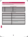
12 Specifications 56
12-1 UPS System Technical Specifications 56
12-2 UPS System Floor Loading Table 56
13 Storage and Service 57
14 Warranty 58
Español 59
Français 117
Русский 175
12-212-93-3141.indb 2 12/28/2012 11:16:51 AM

1
5
9
3
7
11
2
6
10
4
8
12
13
14
3
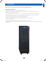
1 – Introduction
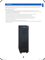
Tripp Lite’s SmartOnline 3-Phase KX2-Series UPS System (Model SU120KX2) is ideal for backing up and protecting data centers,
telecommunications (VoIP), networks, industrial facilities, security/emergency systems and more.
Advanced Features:
• True on-line double conversion with superior IGBT inverter technology
• Low input current THDi allows 1:1 generator sizing for maximum efficiency and cost savings
• Internal N+1 power module redundancy
• Built-in parallel or hot standby redundancy capability for increased capacity or fault-tolerance
• Up to 120kVA capacity in compact footprint; up to 480kVA in parallel capacity configuration with 4 units
• High input power factor and high efficiency with low thermal loss and low noise
• Simplified, easy-to-repair, long-life, high-availability system design
• Redundant auxiliary power and control circuits within each power module and at the system level
• Single feed input design
• Supports external battery cabinets for extended battery backup runtime
• High-resolution LCD status screen simplifies operation and delivers detailed operational information, including system block diagrams
12-212-93-3141.indb 3 12/28/2012 11:16:51 AM

1
5
9
3
7
11
2
6
10
4
8
12
13
14
4
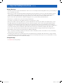
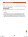
2 – Important Safety Instructions
SAVE THESE INSTRUCTIONS
All sections of this manual contains instructions and warnings that should be followed during the installation and operation of the UPS
systems described in this manual. Read all instructions thoroughly before attempting to move, install or operate the UPS systems described in
this manual. Failure to comply may invalidate the warranty and cause property damage and/or personal injury.
Location Warnings
• Install the UPS system in a controlled indoor environment, away from moisture, temperature extremes, flammable liquids and gasses, conductive
contaminants, dust and direct sunlight.
• Install the UPS system in a level, structurally sound location.
• The UPS system is extremely heavy; be extremely careful when moving or lifting the unit.
• Operate the UPS system at indoor temperatures between 32° F and 104° F (0° C and 40° C) only. For best results, maintain indoor temperatures
between 62° F and 84° F (17° C and 29° C).
• Leave adequate space around all sides of the UPS system for proper ventilation. Do not block, cover or insert objects into the external ventilation
openings of the cabinet.
• Do not place any object on the unit, especially containers of liquid.
• Do not mount the unit with its front or rear panel facing down (at any angle). Mounting in this manner will seriously inhibit the unit’s internal
cooling, eventually causing product damage not covered under warranty.
• Do not install the UPS system near magnetic storage media, as this may result in data corruption. Keep all recorded magnetic media a minimum
of 60 cm (24 inches) away from the UPS system.
• Do not attempt to stack the UPS system. Attempting to stack the UPS system may cause permanent damage and create a potential for serious
personal injury.
• The casters are designed for minor position adjustments within the final installation area only. The casters are not designed for moving the UPS
system over longer distances.
• The casters are not designed to provide long-term support for the UPS system after final installation. Use the levelers to provide long-term
support.
• When moving the UPS system, push from the front or rear, not from the sides.
• Do not attempt to unpack or move the UPS system without assistance.
Connection Warnings
• The power supply for the UPS system must be 3-phase rated in accordance with the equipment nameplate. It also must be suitably
grounded and wired according to all applicable national and local electrical wiring standards, codes and regulations.
• The UPS system contains hazardous high voltages that have the potential to cause personal injury or death from electric shock.
• The UPS system has its own energy source (battery – internal and/or external). The output terminals may be live even when the UPS system is
not connected to an AC supply.
• If the UPS system receives power from a motor-powered AC generator, the generator must provide clean, filtered, computer-grade output.
• Use of this equipment in life support applications where failure of this equipment can reasonably be expected to cause the failure of the life
support equipment or to significantly affect its safety or effectiveness is not recommended. Do not use this equipment in the presence of a
flammable anesthetic mixture with air, oxygen or nitrous oxide.
• The UPS system is designed to power modern computer loads and associated peripheral devices. Do not use the UPS system to power pure
inductive or capacitive loads.
• Input and output wiring should be performed by trained, qualified electricians only.
• Due to high leakage current, a proper earth ground connection is essential before connecting the AC supply.
• Isolate the UPS system before working on the circuit. An easily accessible disconnect device should be incorporated in the fixed wiring. The
disconnect device must disconnect all line conductors simultaneously when opened.
12-212-93-3141.indb 4 12/28/2012 11:16:52 AM

1
5
9
3
7
11
2
6
10
4
8
12
13
14
5
2 – Important Safety Instructions (continued)
Battery Warnings
• The UPS system does not require routine maintenance. There are no user-serviceable parts inside. Only qualified service personnel should open
the access panels for any reason.
• Batteries present a risk of electrical shock and burns from high short-circuit current. Battery connection or replacement should be performed
only by qualified service personnel, observing proper precautions. Turn off the UPS system before connecting or disconnecting internal
batteries. Use tools with insulated handles. Do not open the batteries. Do not short or bridge the battery terminals with any object.
• Replace batteries with equivalent batteries available from Tripp Lite. Do not operate the UPS system without batteries.
• The batteries are recyclable. Refer to local codes for disposal requirements.
• Do not dispose of the batteries in a fire, mutilate the batteries or open the battery coverings.
• Battery fuses should be replaced by qualified service personnel only. Blown fuses must be replaced with the same number and type of fuses.
• Potentially lethal voltages exist within the UPS system as long as the battery supply is connected. Service and repair should be performed
by trained personnel only, while the UPS system is turned off or placed into bypass mode. Disconnect internal batteries (if present) before
performing any service work by switching off the internal battery circuit breaker and removing the battery fuse(s). Disconnect external batteries
(if present) by switching off the external battery cabinet breaker and disconnecting the external battery cabling from the UPS system.
• Do not connect or disconnect batteries when the UPS system is operating from the battery supply or when the unit is not in bypass mode.
• External batteries must be replaced by equivalent batteries available from Tripp Lite.
• Before connecting an external battery cabinet to the UPS system, read the external battery cabinet’s documentation. Use only external battery
cabinets that have been approved by Tripp Lite.
• If the UPS system remains off for an extended period of time, it should be turned on periodically to allow the batteries to recharge. The UPS
system should be turned on and the batteries should be recharged at least one uninterrupted 24-hour period every 3 months. Failure to recharge
the batteries periodically may cause irreversible battery damage.
Wiring Warnings
• See Section 6-1 for wiring warnings
12-212-93-3141.indb 5 12/28/2012 11:16:52 AM

1
5
9
3
7
11
2
6
10
4
8
12
13
14
A E F G H I J KBCD
6
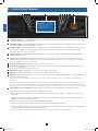
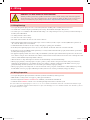
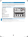
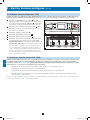
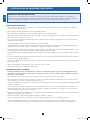
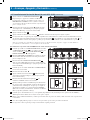
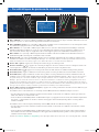
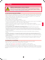
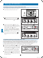
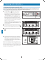
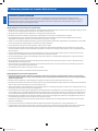
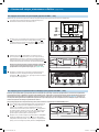
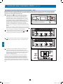
3 – Control Panel Features
• “NORMAL” LED: This green light illuminates to indicate that the UPS system is in online (normal) mode. The primary AC input supply is
present and within standard operating parameters.
• “BATTERY” LED: This amber light illuminates when the UPS system is in battery backup mode, discharging the batteries to provide power
to connected equipment. An audible alarm will also sound.
• “BYPASS” LED: This amber light illuminates when the UPS system is in bypass mode (auto bypass or manual bypass). Battery backup
power will not be available to connected equipment while the UPS system is in bypass mode, but connected equipment loads will be
supported by the bypass (reserve) power source.
• “FAULT” LED: This red light illuminates when any UPS system or input power fault occurs. Available diagnostic information will be
displayed on the LCD screen.
• LCD Status Screen: This illuminated LCD status screen displays text and graphics to indicate a wide range of UPS system operating
conditions and diagnostic data. Note: The LCD backlight will turn off after 10 minutes of inactivity. Turn on the backlight by momentarily
pressing the ON button or one of the scroll buttons.
• “ESC” (Escape) Button: Press this button to return to the previous page or menu.
• Scroll Buttons ( and ): Press these buttons to move the cursor up or down and navigate the control panel menus and screens. These
buttons are also used for data entry in several screens.
• Enter Button ( ): Press this button to select a menu item or confirm a setting change.
• ON Button: Press and hold this button for 3 seconds to turn the UPS system’s inverter ON.
• OFF Button: Press and hold this button for 3 seconds to turn the UPS system’s inverter OFF. If the UPS system is in online (normal) mode, it
will switch to auto bypass mode.
Note: Switching the inverter OFF does not stop the converter stage of the UPS and therefore, the connected battery is still charging as
required.
Note: After switching the inverter OFF, if the battery circuit breaker or AC main input circuit breaker are opened and remain open for an
extended period of time, the batteries should be recharged periodically. At a minimum, the batteries should be charged for an uninterrupted
24-hour period every 3 months to maintain their longest usable life. Failure to recharge the batteries may cause irreversible battery damage.
• “EPO” (Emergency Power Off) Button: Press this button to turn the UPS system’s output OFF and also disable bypass output.
If the UPS system is in battery backup mode when the EPO button is activated:
• Main output and bypass output are turned off, the alarm sounds, fans shut down after approximately one minute, and control circuitry
remains active.
• Releasing the EPO button (by pressing it again) turns off the UPS system completely, including the alarm and control circuit. Press the
ON button for 3 seconds to restart the UPS system.
If the UPS system is in online (normal) mode when the EPO button is activated:
• Main output and bypass output are turned off, the alarm sounds, fans and control circuitry remain active.
• Releasing the EPO button (by pressing it again) turns off the alarm and places the UPS system in auto bypass mode. Press the ON button
for 3 seconds to return the UPS system to online (normal) mode.
See Section 10 – Display and Configuration for detailed information about the control panel’s menus and displays.
A
B
C
D
E
F
G
H
I
J
K
12-212-93-3141.indb 6 12/28/2012 11:16:53 AM

1
5
9
3
7
11
2
6
10
4
8
12
13
14
A
B
C
G
G
H H
F
D E
7
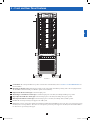
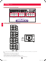
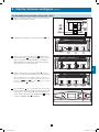
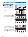
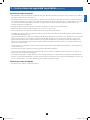
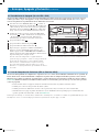
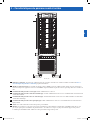
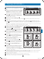
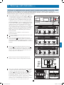
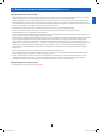
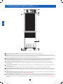
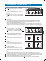
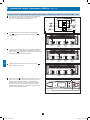
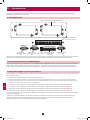
4 – Front and Rear Panel Features
• Control Panel: The control panel allows the operator to monitor and control the UPS system. See Section 3 – Control Panel Features for
more information.
• Internal Power Modules: 20kVA internal power modules can be replaced in the field without powering down connected equipment loads.
The SU120KX2 contains 6 internal power modules capable of N+1 redundancy.
• Output Circuit Breaker Switch (Q4): Controls AC output power.
• Manual Bypass Circuit Breaker Switch (Q3): Controls AC input power to the UPS system during manual bypass operation.
• Bypass Input Circuit Breaker Switch (Q2): Controls AC input power to the UPS system during auto bypass operation.
• Main Input Circuit Breaker Switch (Q1): Controls AC input power to the UPS system during online (normal) operation.
• Levelers: The levelers provide long-term support for the UPS system.
• Casters: The casters are designed for small position adjustments within the final installation location only; they are not designed for moving
the UPS system over longer distances. The casters are not designed to provide long-term support for the UPS system after final installation.
Use the levelers to provide long-term support.
A
B
C
D
E
F
G
H
Front View
12-212-93-3141.indb 7 12/28/2012 11:16:56 AM

1
5
9
3
7
11
2
6
10
4
8
12
13
14
H
L
H
O
N
M
J
K
I I
8
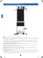
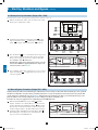
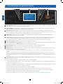
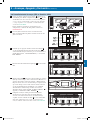
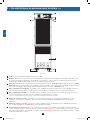
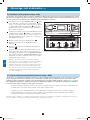
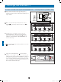
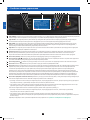
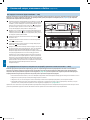
• Levelers: The levelers provide long-term support for the UPS system.
• Casters: The casters are designed for small position adjustments within the final installation location only; they are not designed for moving
the UPS system over longer distances. The casters are not designed to provide long-term support for the UPS system after final installation.
Use the levelers to provide long-term support.
• Accessory Slot: Remove the cover panel to install a Tripp Lite SNMPWEBCARD accessory. The SNMPWEBCARD accessory provides an
Ethernet interface for the UPS system and enables remote monitoring and control via SNMP, Web browser or telnet. Visit www.tripplite.com
for more information about the SNMPWEBCARD accessory.
• RS-232 Serial Communications Port: This DB9 port connects the UPS system to compatible workstations or servers, enabling automatic
shutdown during extended blackouts and monitoring of operating and power conditions.
• Parallel Configuration Port: These DB9 ports connect the UPS system to another UPS system, or chain of systems, of identical type and
capacity for use in a parallel configuration (up to 4 systems).*
*A pair of DIP switches are set to 1/On or 0/Off on each UPS, depending on the parallel configuration.
• Input Dry Contact Interface: This interface receives dry contact signals that allow the UPS system to receive commands and monitor
external battery conditions. See Section 11 - Communications for more information.
• Output Dry Contact Interface: This interface allows the UPS system to send information via dry contact communications. See Section 11 –
Communications for more information.
• Terminal Block Cover: Remove the terminal block cover to access the UPS system’s input, bypass input, external battery cabinet, output and
grounding connection terminals. Wiring conduits pass through the circular knockouts in the terminal block cover. See Section 6 – Wiring for
more information, including a detailed diagram of the terminal block.
H
I
J
K
L
M
N
O
4 – Front and Rear Panel Features (continued)
Rear View
12-212-93-3141.indb 8 12/28/2012 11:17:05 AM

1
5
9
3
7
11
2
6
10
4
8
12
13
14
1
2-3
4-5
9
5 – Cabinet Installation
Read Section 2 – Important Safety Instructions Before Installation
5-1 Preparation
The UPS system must be installed in a structurally sound area with a level floor that is able to bear the weight of the UPS system, any external
battery cabinet and other equipment that will be installed nearby. The installation site should also have a dedicated AC circuit available that is
compatible with the UPS system’s input requirements. (See Section 12 – Specifications for details on input requirements and floor loading
requirements.) Before unpacking the unit, you should transport the shipping container closer to the final installation site to minimize the distance
you will need to move the unit after the protective shipping container has been removed. If you plan to store the UPS system for an extended
period before installation, follow the instructions in Section 13 – Storage and Service. (Unpacking and storage instructions are also printed on the
“Unpacking and Storage Instructions” sheet secured to the shipping container.) Warning: Do not attempt to unpack or move the UPS system
without assistance.
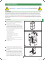
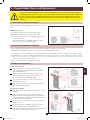
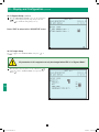
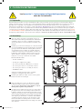
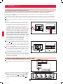
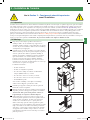
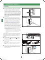
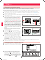
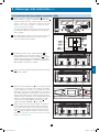
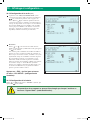
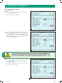
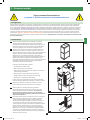
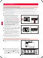
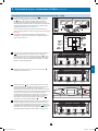
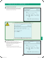
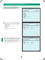
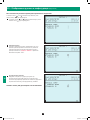
5-2 Unpacking
• Inspect the shipping container(s) for visible damage. If you
determine that the unit has been damaged during shipping, contact
Tripp Lite for assistance. Do not attempt to use the UPS system if
it has been damaged or mishandled.
• Confirm that the shipping container is upright and use a
screwdriver to remove its top panel, front panel and back panel.
Also remove the plastic wrap and interior cushioning material.
Confirm that the model name and rating at the rear of the cabinet
match the unit you ordered. Examine the cabinet for any damaged
or loosened parts. Confirm that the shipping container includes the
accessories that ship with the unit.
The UPS system should include:
• AnRS-232serialcable
• Aparallelconfigurationcable
• AremoteEPOwiringconnector(2contacts)
• Adryinputcontactconnector(4contacts)
• Adryoutputcontactconnector(12contacts)
• SoftwareCD-ROM
If any of the package contents are missing or damaged, please
contact Tripp Lite for assistance.
• Confirm that the unit is stable, then remove the side panels from
the shipping container.
• Remove the bolts from the shipping brackets securing the unit
to the pallet, then remove the shipping brackets from the UPS
system. Warning: Be extremely careful, as the unit could shift
unexpectedly.
• Use several of the screws you removed in step 2 to attach the top
panel of the shipping container to the front edge of the shipping
pallet. The smooth surface of the panel should face upward so
that it can be used as a ramp for rolling the unit off the shipping
pallet. Do not attempt to use the top panel as a ramp if it is cracked
or otherwise structurally damaged. Make sure the casters at the
bottom of the unit are unlocked. Using extreme caution, slowly roll
the unit down the ramp with the aid of several assistants.
1
2
3
4
5
12-212-93-3141.indb 9 12/28/2012 11:17:18 AM

1
5
9
3
7
11
2
6
10
4
8
12
13
14
3
4
A
B
1
2
100 cm (39.4 in.)
50 cm (19.7 in.)
50 cm (19.7 in.)
5
10
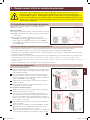
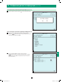
5 – Cabinet Installation (continued)
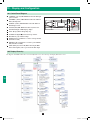
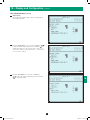
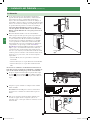
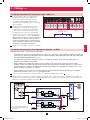
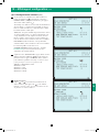
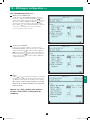
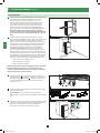
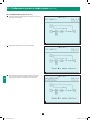
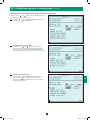
5-3 Placement
• Use the casters to move the UPS system for a short distance over
a level, smooth, stable surface. Do not attempt to use the casters
to move the UPS system over longer distances. The UPS system
should be moved close to its final installation location inside
its shipping container before it is unpacked from the shipping
container. Use a mechanical device of sufficient capacity to move
the shipping container. Warning: The UPS system could tip if it
is moved over an unstable surface. Be extremely careful when
moving the UPS system. Push the UPS system from the front or
rear, not from the sides.
• Position the UPS system in a structurally sound area with a
level floor that is able to bear the weight of the UPS system,
any external battery cabinets and other equipment that will be
installed nearby. The installation site should also have a dedicated
AC circuit available that is compatible with the UPS system’s
input requirements. (See the Section 12 – Specifications for
more information about input requirements and floor loading
requirements.) The UPS system must be installed in a clean,
secure environment with a relative humidity less than 90% (non-
condensing). Operate the UPS system at indoor temperatures
between 17° C and 29° C (62° F and 84° F). Prevent damage to
cabling by using suitable protective conduits. In order to maintain
proper airflow and service access, you must maintain the following
clearances:
• At least 100 cm (39.4”) clearance in front of the UPS system.
• At least 50 cm (19.7”) clearance behind the UPS system.
• At least 50 cm (19.7”) clearance above the UPS system.
Warning: The cooling fans circulate air from front to back. Do not
use any air conditioning or fan that blows air directly toward the
rear of the UPS system.
• After moving the UPS system to its final location, lock the casters
A
and use the levelers
B
to stabilize the cabinet. Ensure that all
four levelers make firm contact with the floor.
• Attach the balance supports on either side of UPS using 4 bolts.
Caution: The UPS system may topple over in unexpected
circumstances if both balance supports are not properly installed.
• For emergency use, install a fire extinguisher rated for energized
electrical equipment fires (Class C rating or exact equivalent, with
a non-conductive extinguishing agent) near the UPS system.
1
2
3
4
5
12-212-93-3141.indb 10 12/28/2012 11:17:21 AM

1
5
9
3
7
11
2
6
10
4
8
12
13
14
11
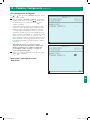
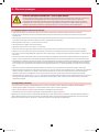
6 – Wiring
DANGER! LETHAL HIGH VOLTAGE HAZARD!
All wiring should be performed by a qualified electrician in accordance with the warnings in this manual, all applicable
electrical and safety codes, and good wiring practices. Incorrect wiring may damage the UPS system severely and cause
serious personal injury and property damage. Read Section 2 – Important Safety Instructions before proceeding.
6-1 Wiring Warnings
• De-energize all input and output power sources of the UPS system before installing cables or making electrical connections.
• Use flexible cable of sufficient length to permit UPS system servicing. The maximum cable length is 10 m (32.8 ft).
• Use ferrule caps to cover termination cables within mechanical lugs, or use compression lugs in order to prevent frayed ends from shorting on
the UPS system terminal block.
• Use cabling rated VW-1, FT-1 or better.
• Use cable sleeves and connector clamps.
• The neutral conductor must be the same size as the current conductors.
• Tighten all field wiring terminal connections with a torque of at least 3.95 N·m (35 in·lb); a torque of 11.8 N·m (100 in·lb) is required for the
“In”, “Out” and “Battery” bolt-screw terminals.
• Confirm that all cables are marked correctly according to their purpose, polarity, phase and diameter.
• If the UPS system’s input/output power source is wye-wye, then “Neutral” and “Ground” must not be re-bonded at the UPS.
• If the input power source has VNG>0, install a grounded wye secondary isolation transformer with a properly bonded neutral to ground before
the UPS system and input power source.
• For equipment requiring a neutral connection to an IT power distribution system that requires neutral isolation upon disconnect, the disconnect
device must be a four-pole device and must disconnect all line conductors and the neutral conductor. If a disconnect device interrupts the neutral
conductor, it must simultaneously interrupt all line conductors.
• Allow the batteries to charge uninterrupted for 24 hours after the initial wiring connection and UPS startup.
• Observe proper polarity by connecting negative to negative, positive to positive and the center point of the battery string to the normal “N”
terminal. Do not bond the battery’s “N” terminal to the AC power “Neutral” or “Ground” as damage may result. Failure to observe proper
polarity will damage the UPS system and create a serious risk of personal injury and property damage.
• Observe proper phase by connecting R to R, S to S, T to T and N to N. Source power phase rotation must be verified as RST before powering
the UPS. Failure to observe proper phase will damage the UPS system and create a risk of personal injury and property damage.
6-2 Wiring Preparation
• De-energize all input and output (AC and DC) of the UPS system and external battery cabinet (if present).
• Mark all cables according to their correct purpose, polarity, phase and diameter.
• Review the diagrams in Section 6-3 and Section 6-4 to familiarize yourself with the terminal blocks.
• Consult the table in Section 6-5 to find the correct electrical input/output characteristics for the UPS system.
Note: If the UPS system’s input/output power source is wye-wye, then “Neutral” and “Ground” must not be re-bonded at the UPS. If the input
power source has VNG>0, install an isolation transformer as part of the UPS input power source and bond “Neutral” and “Ground” together at
the isolation transformer’s output.
12-212-93-3141.indb 11 12/28/2012 11:17:22 AM

1
5
9
3
7
11
2
6
10
4
8
12
13
14
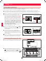
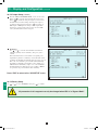
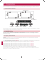
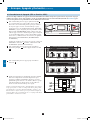
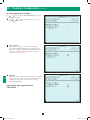
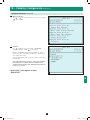
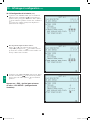
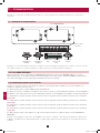
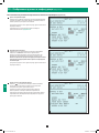
AC Input Battery Output
Grounding Terminals
R RS ST TN NN
+
–
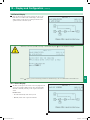
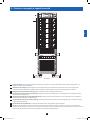
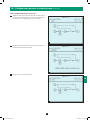
12
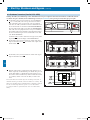
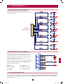
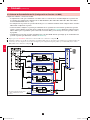
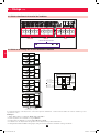
6 – Wiring (continued)
Battery and Circuit Breaker Diagram shown for illustration only; consult the battery cabinet’s documentation for exact specifications.
Notes:
• All internal wiring is UL-listed, MTW, 125C Hi-Flex cable.
• Terminal block is UL-recognized and rated for 600 VDC.
• Breaker is UL-listed and rated for 250 A, 600 VDC, 25 KAIC.
• Cabinets with breakers are shipped with the breaker in the off/open position.
• Battery arrangements shown are typical but may vary depending on cabinet and battery type.
6-3 UPS System Terminal Block Diagram
6-4 External Battery Cabinet Wiring Diagrams
12-212-93-3141.indb 12 12/28/2012 11:17:22 AM

1
5
9
3
7
11
2
6
10
4
8
12
13
14
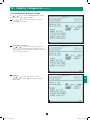
13
6 – Wiring (continued)
6-4 External Battery Cabinet Wiring Diagrams (continued)
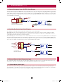
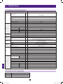
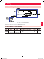
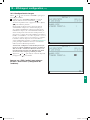
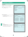
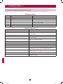
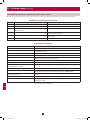
6-5 Electrical and Cable Data
SU120KX2 schematic representation shown
External Battery Cabinets
10 Year Cabinet: 55AH, 78AH, 103AH, 140AH; 250A, 600VDC Circuit Breaker
Model Input Output
Input, Bypass and
Output Breaker Size
Input, Reserve, Output
and Battery Cable Size
Battery Circuit
Breaker Fuse Size
Battery
Cable Size
SU120KX2
380Y/220V,
400Y/230V, or
415Y/240V AC, 3Ø,
4-wire + ground
380Y/220V,
400Y/230V, or
415Y/240V AC, 3Ø,
4-wire + ground
225A
120mm²
(4/0 AWG)
250A
120mm²
(4/0 AWG)
12-212-93-3141.indb 13 12/28/2012 11:17:23 AM

1
5
9
3
7
11
2
6
10
4
8
12
13
14
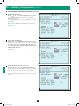
4
3
1
2
Q4 Q2 Q1Q3
A
B
14
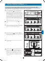
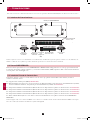
6 – Wiring (continued)
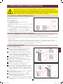
6-6 External Battery Cabinet Wiring
Warning: External battery cabinets vary. Read the external battery cabinet’s documentation before attempting to connect it to the UPS
system. Use only external battery cabinets that have been approved by Tripp Lite.
Note: An external battery cabinet is required with model SU120KX2. Contact Tripp Lite for external battery cabinet ordering information.
• De-energize all input and output (AC and DC) of the UPS system and external battery cabinet, and confirm that the external battery cabinet
breaker switch
is off. (If the UPS system has already been wired to an AC power source, see Section 8-6 for shutdown instructions.)
• Remove the terminal block covers from the UPS. Remove the front cover and conduit plates (if provided) of the external battery cabinet.
• Connect the positive (+), normal (N) and negative (-) UPS
system connection terminals of the external battery cabinet to the
corresponding positive (+), normal (N) and negative (-) external
battery connection terminals of the UPS system. See Section 6-3
and the external battery cabinet’s documentation for terminal
block diagrams. See Section 6-4 for wiring diagrams. See Section
6-5 for cable size requirements. Cabling should be protected by
flexible conduit and routed through the appropriate knockouts in
the terminal block cover. Warning: Observe proper polarity by
connecting negative to negative, positive to positive and center
point of the battery string to normal “N”. Failure to observe
proper polarity will damage the UPS system and create a risk
of personal injury and property damage.
Note: Do not bond the battery “N” terminal to the AC power
neutral or ground as damage may result.
• Connect the external battery cabinet’s grounding terminal
A
to the
UPS system’s corresponding grounding terminal
B
with a 4 AWG
(25 mm²) ground cable. Keep the ground cable connected at all
times after installation.
• Connect the UPS system’s primary grounding terminal
to
your facility’s earth ground
with a 4 AWG (25 mm²) minimum
equipment grounding conductor (EGC) cable within the same
conduit used in item 3 above. Keep the EGC cable connected at all
times after installation.
• Replace the conduit landing cover of the external battery cabinet. If
you do not plan to wire the AC input/output of the UPS system at
this time, replace the terminal block cover of the UPS system.
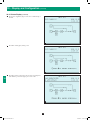
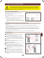
6-7 AC Input/Output Wiring (Single UPS—SUS)
• After de-energizing all input and output (AC and DC) of the UPS
system, remove the terminal block cover from the UPS system.
• Remove the UPS system’s front bezel to expose the circuit
breakers. First, confirm that the main input circuit breaker switch
Q1
and the bypass input circuit breaker switch
Q2
are both off.
Second, confirm that the manual bypass circuit breaker switch
Q3
is off. Third, confirm that the output circuit breaker switch
Q4
is
off.
1
2
3
4
5
6
1
2
12-212-93-3141.indb 14 12/28/2012 11:17:25 AM

1
5
9
3
7
11
2
6
10
4
8
12
13
14
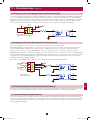
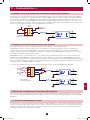
1
DASHED LINES INDICATE USER-SUPPLIED
PARTS AND CABLES.
AC Input Battery Output
Grounding Terminals
R RS ST TN NN
+
–
15
6 – Wiring (continued)
6-7 AC Input/Output Wiring (Single UPS—SUS) (continued)
3
4
5
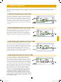
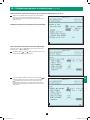
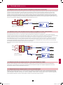
6-8 AC Input/Output Wiring: Parallel Configuration – 2x MUS (Multiple Unit System)
Parallel Configuration – MUS Warnings:
• The total cable length for each UPS must be within 10% of each of the other parallel-configured UPS in order to prevent
unbalanced load sharing between the individual UPS. (IP1 + OP1 = IP2 + OP2 = IP3 + OP3 = IP4 + OP4, minimum/maximum
deviation must be < 10%).
• Parallel configurations are supported for 2, 3, or 4 UPS units only. Do not attempt to configure more than 4 UPS systems via
parallel configuration.
• Each UPS system to be parallel configured for either N+1 redundancy or capacity, must have the same rating, kVA capacity, and
system and power module level firmware version (see Section 10-6). Attempting to configure dissimilar UPS systems may be
inhibited or may cause damage to the UPS systems and create a risk of personal injury and property damage.
• Each UPS must have its parallel group set to 2 and a different “Parallel ID” that indicates the UPS systems are operating in
parallel (see Section 10-5-5 for more details).
• Follow the steps in Section 6-7, wiring the UPS systems as shown in the diagram
1
.
• Each UPS is shipped with (1) parallel configuration cable included. Connect each UPS parallel communication port(s) as shown and select
the correct position of the parallel port dip switches (either both ON (down) or both OFF (up) as shown in the diagram
1
.
1
2
• Connect the UPS system’s primary grounding terminal
to your facility’s earth ground with a 4 AWG (25 mm²)
minimum equipment grounding conductor cable. Keep
the EGC cable connected at all times after installation.
• Confirm the phase of each cable, then connect the cables
according to the UPS system terminal block diagram in
Section 6-3. See Section 6-5 for cable size requirements.
Cabling should be protected by flexible conduit and
routed through the appropriate knockouts in the terminal
block cover. Warning: Observe proper phase rotation
by connecting R to R, S to S, T to T and N to N.
Failure to observe proper phase rotation will damage
the UPS system and create a risk of personal injury
and property damage.
• Replace the UPS system’s terminal block cover.
12-212-93-3141.indb 15 12/28/2012 11:17:25 AM

1
5
9
3
7
11
2
6
10
4
8
12
13
14
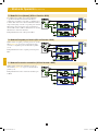
1
DASHED LINES INDICATE USER-SUPPLIED
PARTS AND CABLES.
16
6 – Wiring (continued)
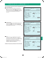
6-9 AC Input/Output Wiring: Parallel Configuration – 4x MUS (Multiple Unit System)
Parallel Configuration – MUS Warnings:
• The total cable length for each UPS must be within 10% of each of the other parallel-configured UPS in order to prevent
unbalanced load sharing between the individual UPS. (IP1 + OP1 = IP2 + OP2 = IP3 + OP3 = IP4 + OP4, minimum/maximum
deviation must be < 10%).
• Parallel configurations are supported for 2, 3, or 4 UPS units only. Do not attempt to configure more than 4 UPS systems via
parallel configuration.
• Each UPS system to be parallel configured for either N+1 redundancy or capacity, must have the same rating, kVA capacity, and
system and power module level firmware version (see Section 10-6). Attempting to configure dissimilar UPS systems may be
inhibited or may cause damage to the UPS systems and create a risk of personal injury and property damage.
• Each UPS must have its parallel group set to 2 and a different “Parallel ID” that indicates the UPS systems are operating in
parallel (see Section 10-5-5 for more details).
• Follow the steps in Section 6-7, wiring the UPS systems as shown in the diagram
1
.
• Each UPS is shipped with (1) parallel configuration cable included. Connect each UPS parallel communication port(s) as shown and select
the correct position of the parallel port dip switches (either both ON (down) or both OFF (up) as shown in the diagram
1
.
1
2
12-212-93-3141.indb 16 12/28/2012 11:17:26 AM

1
5
9
3
7
11
2
6
10
4
8
12
13
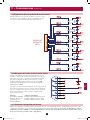
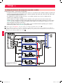
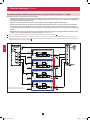
14
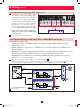
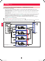
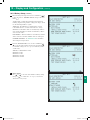
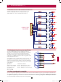
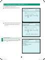
Q2
Q3
Q1
STS
Q4
FB
FB
FB
6 X 20KVA MODULES
3 PH, 4W + G
POS, NEG, N + G
3 PH, 4W + G
IN
OUT
EXT BATT
PARALLEL
PORTS
CLOSED
CLOSED
CLOSED
OPEN
CLOSED
STS
FB
FB
17
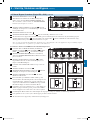
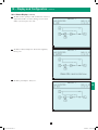
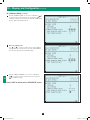
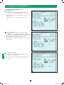
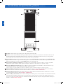
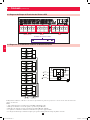
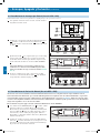
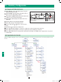
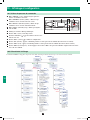
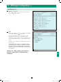
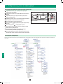
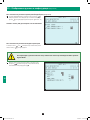
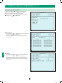
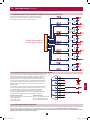
7 – Operating Modes
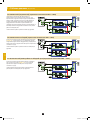
This section provides a basic description of the UPS system’s operating modes. The one-line diagrams used are schematic representations. For
more information about switching between operating modes, refer to Section 8 – Start-Up, Shutdown and Bypass.
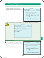
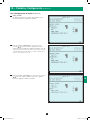
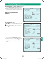
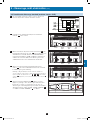
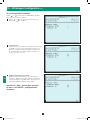
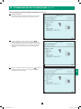
7-1 Online (Normal) Mode (Single UPS—SUS)
In online (normal) mode, the UPS system’s rectifier converts incoming
AC utility power to DC power that charges the batteries and supplies the
inverter. The inverter transforms the DC power to precision-regulated,
pure sine wave AC power that supports the operation of connected
equipment. This dual conversion technology isolates connected
equipment from all power problems and ensures that connected
equipment receives ideal power at all times.
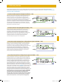
7-2 Battery Backup Mode (Single UPS—SUS)
When a power outage or other extreme power event occurs, the UPS
system automatically switches from normal mode to battery backup
mode. The UPS system’s batteries (internal and/or external) provide
emergency DC power to the inverter. The inverter transforms the DC
power to precision-regulated, pure sine wave AC power that supports
the operation of connected equipment.
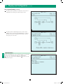
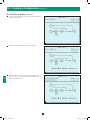
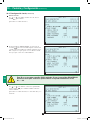
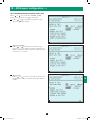
7-3 Auto Bypass Mode (Single UPS—SUS)
If the inverter malfunctions due to excessive temperature, overload,
output short circuit, abnormal voltage or battery problems, the inverter
will shut down. If the UPS system detects a bypass (reserve) power
source that conforms to normal parameters, then the UPS system
automatically switches to auto bypass mode to continue supplying
power to connected equipment. When all problems are eliminated, the
UPS system switches back to online (normal) mode automatically.
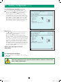
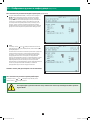
7-4 Manual Bypass Mode (Single UPS—SUS)
If UPS system maintenance or repair is required, you can bypass
the UPS system and enable bypass (reserve) power manually. After
confirming that the bypass source is present (input AC available and Q3
open), transfer to manual bypass mode by first pressing the off button to
stop the inverter. This transfers the UPS to static internal bypass. Next,
switch the UPS system into manual bypass mode. (See Section 8-5 for
complete manual bypass procedure.) The one-line diagram illustrates
the system status and flow of power after the manual bypass procedure
has been completed. This allows service technicians to perform
maintenance or repair procedures without interrupting the flow of AC
power to connected equipment. Warning: After switching to manual
bypass mode to perform selected maintenance or repair procedures,
the UPS may require complete shutdown to affect those repairs. Use
of an external 3-breaker maintenance bypass panel can facilitate
this and still maintain AC power to the connected equipment.
12-212-93-3141.indb 17 12/28/2012 11:17:27 AM

1
5
9
3
7
11
2
6
10
4
8
12
13
14
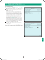
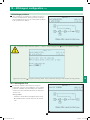
18
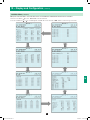
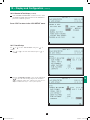
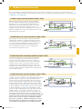
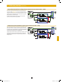
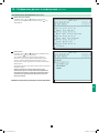
7 – Operating Modes (continued)
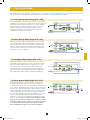
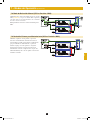
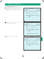
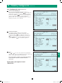
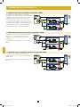
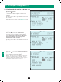
7-5 Online (Normal) Mode (Parallel UPS—MUS)
Parallel configuration provides UPS system redundancy or
increased total capacity. Under parallel configuration, the
total load is shared by 2 to 4 UPS systems. If one of the UPS
systems malfunctions, the total connected equipment load
is supported by the remaining UPS systems. If the total load
exceeds the capacity of the remaining UPS systems, the MUS
will switch all UPS units to auto bypass mode.
The diagram illustrates the on-line mode for a 2x MUS.
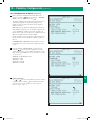
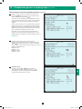
7-6 Battery Backup Mode (Parallel UPS—MUS)
Similar to battery backup mode for a single UPS system
(Section 7-2), except the total connected equipment load is
shared by the parallel UPS systems (2 to 4).
The diagram illustrates the battery backup mode for a
2x MUS.
7-7 Auto Bypass Mode (Parallel UPS—MUS)
Similar to auto bypass mode for a single UPS system
(Section 7-3), except with parallel UPS systems (2 to 4).
The diagram illustrates the auto bypass mode for a 2x MUS.
12-212-93-3141.indb 18 12/28/2012 11:17:28 AM

1
5
9
3
7
11
2
6
10
4
8
12
13
14
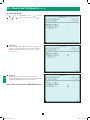
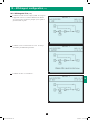
19
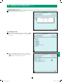
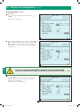
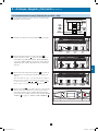
7 – Operating Modes (continued)
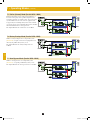
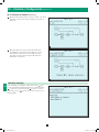
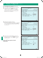
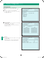
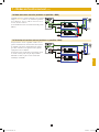
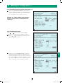
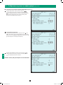
7-8 Manual Bypass Mode (Parallel UPS—MUS)
Similar to manual bypass mode for a single UPS system
(Section 7-4), except with parallel UPS systems (2 to 4).
Note: All UPS systems must be switched into manual bypass
mode.
The diagram illustrates the manual bypass mode for a
2x MUS.
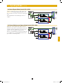
7-9 External Maintenance Bypass Mode (Parallel UPS—MUS)
Utilizing the external parallel cabinet with system level
maintenance bypass panel, the parallel UPS systems can be
completely isolated for maintenance or repair procedures
while the connected equipment remains powered.
Transfer to external maintenance bypass mode should only
be accomplished once each individual UPS unit has been
placed in auto or manual bypass first.
12-212-93-3141.indb 19 12/28/2012 11:17:29 AM

1
5
9
3
7
11
2
6
10
4
8
12
13
14
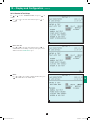
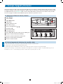
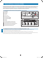
Control Panel
Circuit Breaker Switches (UPS System Front Panel)
1
2
E
F
G
K
A
B
C
D
H
I
J
Q4
Q3
Q2
Q1
Output Manual
Bypass
Bypass
Input
Main
Input
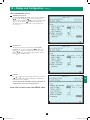
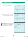
20
8 – Start-Up, Shutdown and Bypass
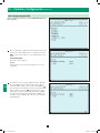
Warning: The UPS system’s output voltage and frequency are set at 220/380V, 50Hz by default. If you require output voltage of 230/400V
or 240/415V, or a frequency of 60Hz, you must change the UPS system’s output voltage and/or frequency by accessing the output setup
menu described in Section 10-5-2. You must place the UPS system in bypass mode before changing the output voltage. Do not connect your
equipment to the UPS system’s output until you have set the proper parameters.
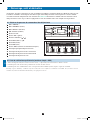
8-1 Control Panel and Breaker Diagrams
• “NORMAL” LED
• “BATTERY” LED
• “BYPASS” LED
• “FAULT” LED
• LCD Status Screen
• “ESC” (Escape) Button
• Scroll Buttons ( and )
• Enter Button ( )
• ON Button
• OFF Button
• “EPO” (Emergency Power Off) Button
• Main Input Circuit Breaker Switch
• Bypass Input Circuit Breaker Switch
• Manual Bypass Circuit Breaker Switch
• Output Circuit Breaker Switch
8-2 Preliminary Checklist (Single UPS—SUS)
• All circuit breaker switches should be off, including the breaker of the external battery cabinet.
• Confirm that no voltage potential exists between Neutral and Ground.
• Confirm that the input power source matches the rating (voltage, frequency and phase) of the UPS system.
Note: After start-up, the UPS system will perform a brief self-test and display the results on the LCD screen. After a successful self-test, the UPS
system will provide AC power to the connected equipment load.
A
B
C
D
E
F
G
H
I
J
K
Q1
Q2
Q3
Q4
12-212-93-3141.indb 20 12/28/2012 11:17:30 AM
La page charge ...
La page charge ...
La page charge ...
La page charge ...
La page charge ...
La page charge ...
La page charge ...
La page charge ...
La page charge ...
La page charge ...
La page charge ...
La page charge ...
La page charge ...
La page charge ...
La page charge ...
La page charge ...
La page charge ...
La page charge ...
La page charge ...
La page charge ...
La page charge ...
La page charge ...
La page charge ...
La page charge ...
La page charge ...
La page charge ...
La page charge ...
La page charge ...
La page charge ...
La page charge ...
La page charge ...
La page charge ...
La page charge ...
La page charge ...
La page charge ...
La page charge ...
La page charge ...
La page charge ...
La page charge ...
La page charge ...
La page charge ...
La page charge ...
La page charge ...
La page charge ...
La page charge ...
La page charge ...
La page charge ...
La page charge ...
La page charge ...
La page charge ...
La page charge ...
La page charge ...
La page charge ...
La page charge ...
La page charge ...
La page charge ...
La page charge ...
La page charge ...
La page charge ...
La page charge ...
La page charge ...
La page charge ...
La page charge ...
La page charge ...
La page charge ...
La page charge ...
La page charge ...
La page charge ...
La page charge ...
La page charge ...
La page charge ...
La page charge ...
La page charge ...
La page charge ...
La page charge ...
La page charge ...
La page charge ...
La page charge ...
La page charge ...
La page charge ...
La page charge ...
La page charge ...
La page charge ...
La page charge ...
La page charge ...
La page charge ...
La page charge ...
La page charge ...
La page charge ...
La page charge ...
La page charge ...
La page charge ...
La page charge ...
La page charge ...
La page charge ...
La page charge ...
La page charge ...
La page charge ...
La page charge ...
La page charge ...
La page charge ...
La page charge ...
La page charge ...
La page charge ...
La page charge ...
La page charge ...
La page charge ...
La page charge ...
La page charge ...
La page charge ...
La page charge ...
La page charge ...
La page charge ...
La page charge ...
La page charge ...
La page charge ...
La page charge ...
La page charge ...
La page charge ...
La page charge ...
La page charge ...
La page charge ...
La page charge ...
La page charge ...
La page charge ...
La page charge ...
La page charge ...
La page charge ...
La page charge ...
La page charge ...
La page charge ...
La page charge ...
La page charge ...
La page charge ...
La page charge ...
La page charge ...
La page charge ...
La page charge ...
La page charge ...
La page charge ...
La page charge ...
La page charge ...
La page charge ...
La page charge ...
La page charge ...
La page charge ...
La page charge ...
La page charge ...
La page charge ...
La page charge ...
La page charge ...
La page charge ...
La page charge ...
La page charge ...
La page charge ...
La page charge ...
La page charge ...
La page charge ...
La page charge ...
La page charge ...
La page charge ...
La page charge ...
La page charge ...
La page charge ...
La page charge ...
La page charge ...
La page charge ...
La page charge ...
La page charge ...
La page charge ...
La page charge ...
La page charge ...
La page charge ...
La page charge ...
La page charge ...
La page charge ...
La page charge ...
La page charge ...
La page charge ...
La page charge ...
La page charge ...
La page charge ...
La page charge ...
La page charge ...
La page charge ...
La page charge ...
La page charge ...
La page charge ...
La page charge ...
La page charge ...
La page charge ...
La page charge ...
La page charge ...
La page charge ...
La page charge ...
La page charge ...
La page charge ...
La page charge ...
La page charge ...
La page charge ...
La page charge ...
La page charge ...
La page charge ...
La page charge ...
La page charge ...
La page charge ...
La page charge ...
La page charge ...
La page charge ...
La page charge ...
La page charge ...
La page charge ...
-
 1
1
-
 2
2
-
 3
3
-
 4
4
-
 5
5
-
 6
6
-
 7
7
-
 8
8
-
 9
9
-
 10
10
-
 11
11
-
 12
12
-
 13
13
-
 14
14
-
 15
15
-
 16
16
-
 17
17
-
 18
18
-
 19
19
-
 20
20
-
 21
21
-
 22
22
-
 23
23
-
 24
24
-
 25
25
-
 26
26
-
 27
27
-
 28
28
-
 29
29
-
 30
30
-
 31
31
-
 32
32
-
 33
33
-
 34
34
-
 35
35
-
 36
36
-
 37
37
-
 38
38
-
 39
39
-
 40
40
-
 41
41
-
 42
42
-
 43
43
-
 44
44
-
 45
45
-
 46
46
-
 47
47
-
 48
48
-
 49
49
-
 50
50
-
 51
51
-
 52
52
-
 53
53
-
 54
54
-
 55
55
-
 56
56
-
 57
57
-
 58
58
-
 59
59
-
 60
60
-
 61
61
-
 62
62
-
 63
63
-
 64
64
-
 65
65
-
 66
66
-
 67
67
-
 68
68
-
 69
69
-
 70
70
-
 71
71
-
 72
72
-
 73
73
-
 74
74
-
 75
75
-
 76
76
-
 77
77
-
 78
78
-
 79
79
-
 80
80
-
 81
81
-
 82
82
-
 83
83
-
 84
84
-
 85
85
-
 86
86
-
 87
87
-
 88
88
-
 89
89
-
 90
90
-
 91
91
-
 92
92
-
 93
93
-
 94
94
-
 95
95
-
 96
96
-
 97
97
-
 98
98
-
 99
99
-
 100
100
-
 101
101
-
 102
102
-
 103
103
-
 104
104
-
 105
105
-
 106
106
-
 107
107
-
 108
108
-
 109
109
-
 110
110
-
 111
111
-
 112
112
-
 113
113
-
 114
114
-
 115
115
-
 116
116
-
 117
117
-
 118
118
-
 119
119
-
 120
120
-
 121
121
-
 122
122
-
 123
123
-
 124
124
-
 125
125
-
 126
126
-
 127
127
-
 128
128
-
 129
129
-
 130
130
-
 131
131
-
 132
132
-
 133
133
-
 134
134
-
 135
135
-
 136
136
-
 137
137
-
 138
138
-
 139
139
-
 140
140
-
 141
141
-
 142
142
-
 143
143
-
 144
144
-
 145
145
-
 146
146
-
 147
147
-
 148
148
-
 149
149
-
 150
150
-
 151
151
-
 152
152
-
 153
153
-
 154
154
-
 155
155
-
 156
156
-
 157
157
-
 158
158
-
 159
159
-
 160
160
-
 161
161
-
 162
162
-
 163
163
-
 164
164
-
 165
165
-
 166
166
-
 167
167
-
 168
168
-
 169
169
-
 170
170
-
 171
171
-
 172
172
-
 173
173
-
 174
174
-
 175
175
-
 176
176
-
 177
177
-
 178
178
-
 179
179
-
 180
180
-
 181
181
-
 182
182
-
 183
183
-
 184
184
-
 185
185
-
 186
186
-
 187
187
-
 188
188
-
 189
189
-
 190
190
-
 191
191
-
 192
192
-
 193
193
-
 194
194
-
 195
195
-
 196
196
-
 197
197
-
 198
198
-
 199
199
-
 200
200
-
 201
201
-
 202
202
-
 203
203
-
 204
204
-
 205
205
-
 206
206
-
 207
207
-
 208
208
-
 209
209
-
 210
210
-
 211
211
-
 212
212
-
 213
213
-
 214
214
-
 215
215
-
 216
216
-
 217
217
-
 218
218
-
 219
219
-
 220
220
-
 221
221
-
 222
222
-
 223
223
-
 224
224
-
 225
225
-
 226
226
-
 227
227
-
 228
228
-
 229
229
-
 230
230
-
 231
231
-
 232
232


Tripp Lite SU120KX2 3-Phase UPS Manuel utilisateur
- Catégorie
- Alimentations sans interruption (UPS)
- Taper
- Manuel utilisateur
- Ce manuel convient également à
dans d''autres langues
Documents connexes
-
Tripp Lite 3-Phase UPS Systems Le manuel du propriétaire
-
-
-
-
-
-
-
-
-
Tripp Lite Single-Phase Online Rack UPS Le manuel du propriétaire
