
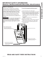
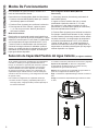
Write the model and serial
numbers here:
Model # _________________
Serial # _________________
You can find them on the rating
label on the front side of your
water heater.
GE is a trademark of the General Electric Company. Manufactured under trademark license.
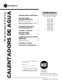
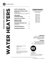
OWNER’S MANUAL
WATER HEATERS
Electronic Residential
49-6000226 Rev. 4 08-20 GEA
GE Branded Electronic
Control Models
GE30S**BLM
GE30S**BMM
GE30T**BLM
GE40S**BLM
GE40S**BMM
GE40T**BLM
GE50S**BLM
GE50S**BMM
GE50T**BLM
SAFETY INFORMATION ..........3
OPERATING INSTRUCTIONS ....6
Control Panel .........................7
Operation Modes ......................8
Hot Water Flexible Capacity (if equipped) . .8
APPLIANCE
COMMUNICATION ................9
CARE AND CLEANING ..........10
INSTALLATION
INSTRUCTIONS ..................14
TROUBLESHOOTING TIPS ......18
Fault Codes .........................19
Wiring Diagram
......................19
LIMITED WARRANTY ...........23
CONSUMER SUPPORT ......... 24
ESPAÑOL
Para consultar una version en
español de este manual de
instrucciones, visite nuestro sitio de
internet GEAppliances.com.
FRANÇAIS
Pour une version français de
ce manuel d’utilisation, veuillez
visiter notre site web à l’adresse
GEAppliances.com.
See http://info.nsf.org/Certified/Lead_
Content/ for specific model listing

2 49-6000226 Rev. 4
THANK YOU FOR MAKING GE APPLIANCES A PART OF YOUR HOME.
Whether you grew up with GE Appliances, or this is your first, we’re happy to have you in the family.
We take pride in the craftsmanship, innovation and design that goes into every GE Appliances
product, and we think you will too. Among other things, registration of your appliance ensures that we
can deliver important product information and warranty details when you need them.
Register your GE appliance now online. Helpful websites and phone numbers are available in the
Consumer Support section of this Owner’s Manual. You may also mail in the pre-printed registration
card included in the packing material.

49-6000226 Rev. 4 3
READ AND SAVE THESE INSTRUCTIONS
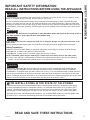
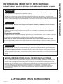
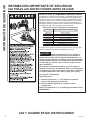
IMPORTANT SAFETY INFORMATION
READ ALL INSTRUCTIONS BEFORE USING THE APPLIANCE
SAFETY INFORMATION
WARNING
For your safety, the information in this manual must be followed to minimize the risk of fire or explosion, electric
shock, or to prevent property damage, personal injury, or loss of life.
Be sure to read and understand the entire Owner’ s Manual before attempting to install or operate this water
heater. It may save you time and cost. Pay particular attention to the Safety Instructions. Failure to follow these
warnings could result in serious bodily injury or death. Should you have problems understanding the instructions
in this manual, or have any questions, STOP and get help from a qualified service technician or the local electric
utility.
CAUTION
Risk of Fire - Hydrogen gas can be produced in a hot water system served by this water heater that has
not been used for a long period of time (generally two weeks or more). HYDROGEN GAS IS EXTREMELY
FLAMMABLE!! To dissipate such gas and to reduce risk of injury, it is recommended that the hot water faucet be
opened for several minutes at the kitchen sink before using any electrical appliance connected to the hot water
system. If hydrogen is present, there will be an unusual sound such as air escaping through the pipe as the water
begins to flow. Do not smoke or use an open flame near the faucet at the time it is open.
WARNING
Risk of Fire - DO NOT store or use gasoline or other flammable vapors and liquids in the vicinity of this or
any other appliance. Keep rags and other combustibles away.
FOR INSTALLATIONS IN THE STATE OF CALIFORNIA
California Law requires that residential water heaters must be braced, anchored or strapped to resist falling
or horizontal displacement due to earthquake motions. For residential water heaters up to 52 gallon (197 L)
capacity, a brochure with generic earthquake bracing instructions can be obtained from: Office of the State
Architect, 400 P Street, Sacramento, CA 95814 or you may call 916.324.5315 or ask a water heater dealer.
Applicable local codes shall always govern installation. For residential water heaters of a capacity greater than
52 gallons (197 L) consult the local building jurisdiction for acceptable bracing procedures.
WARNING
If the water heater has been subjected to flood, fire, or physical damage, turn off power and water to the
water heater.
Do not operate the water heater again until it has been thoroughly checked by qualified service personnel.
Safety Precautions
A. Do turn off power to water heater if it has been subjected to overheating, fire, flood or physical damage.
B. Do Not turn on water heater unless it is filled with water.
C. Do Not turn on water heater if cold water supply shut-off valve is closed.
NOTE: Flammable vapors may be drawn by air currents from surrounding areas to the water heater.
D. If there is any difficulty in understanding or following the Operating Instructions or the Care and Cleaning
section, it is recommended that a qualified person or serviceman perform the work.

4 49-6000226 Rev. 4
SAFETY INFORMATION
READ AND SAVE THESE INSTRUCTIONS
IMPORTANT SAFETY INFORMATION
READ ALL INSTRUCTIONS BEFORE USING THE APPLIANCE
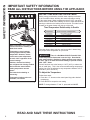
Time/Temperature Relationship in Scalds
Temperature Time to Produce a Serious Burn
120°F (49°C) More than 5 minutes
125°F (52°C) 1-1/2 to 2 minutes
130°F (54°C) About 30 seconds
135°F (57°C) About 10 seconds
140°F (60°C) Less than 5 seconds
145°F (63°C) Less than 3 seconds
150°F (66°C) About 1-1/2 seconds
155°F (68°C) About 1 second
Table courtesy of Shriners Burn Institute
!
Water temperature over 125°F can
cause severe burns instantly or
death from scalds.
Temperature control settings
usually approximate tap water
temperature. However, factors
could cause water temperature
to reach 160°F regardless of the
control settings.
Children, disabled and elderly
are at highest risk of being scalded.
See instruction manual before
setting temperature at water
heater.
Feel water before bathing or
showering.
Temperature limiting valves are
available; see manual.
The chart shown above may be used as a guide in determining
the proper water temperature for your home.
DANGER
There is a Hot Water SCALD Potential if the
water temperature thermostat is set too high. Households
with small children, disabled or elderly persons may require
a 120°F (49°C) or lower thermostat setting to prevent contact
with “HOT” water.
Control has been set at the factory to 120°F (49°C) to reduce the
risk of scald injury. This is the recommended starting temperature
setting, but it can be adjusted to any temperature between 100°F
and 140°F (38°C and 60°C).
To Adjust the Temperature
Follow these steps:
1. Press the + or - buttons on the control panel key pad to desired
temperature.
2. Press ENTER to accept the new setting.
NOTE: To change between °F and °C, press and hold MODE.
WATER TEMPERATURE ADJUSTMENT
Safety, energy conservation, and hot water capacity are factors
to be considered when selecting the water temperature setting
of the water heater. Water temperatures above 125°F can cause
severe burns or death from scalding. Be sure to read and follow the
warnings outlined on the label pictured to the left. This label is also
located on the water heater near the top of the tank.

49-6000226 Rev. 4 5
IMPORTANT SAFETY INFORMATION
READ ALL INSTRUCTIONS BEFORE USING THE APPLIANCE
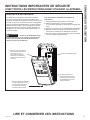
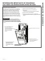
SAFETY CONTROLS
The water heater is equipped with a combination
temperature sensor and high limit Energy-Cut-Off
control (ECO) that is located above the upper heating
element in contact with the tank surface. If for any
reason the water temperature becomes excessively
high, the high limit control (ECO) breaks the power
circuit to the heating element. Once the control
opens, it must be reset manually. Resetting of the
high limit control should be done by a qualified service
technician.
CAUTION
The cause of the high temperature
condition must be investigated by a qualified
service technician and corrective action must be
taken before placing the water heater in service
again.
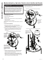
To reset the temperature-limiting control:
1. Turn off the power to the water heater.
2. Remove the electronic control display and insulation.
Open the electronic control housing by removing
the screw beneath the display using a phillips-head
screwdriver. Push the control display down and
rotate the panel from the top to open and remove
the insulation.
The thermostat protective cover should not be
removed.
3. Press the red RESET button.
4. Replace the insulation, control housing, and screw
before turning on the power to the water heater.
5. Ensure water heater is operating properly after
resetting the ECO.
READ AND SAVE THESE INSTRUCTIONS
SAFETY INFORMATION
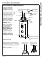
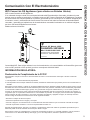
1. Once the Power is turned off at
breaker, remove screw at base
on control housing with Phillps
head screw driver.
2. With a flat blade screw driver,
lower control housing about
1/8” at top pry location, to allow
rotation of control for opening.
ECO reset button location
3. Control can now be rotated
downward to access ECO reset
(beneath insulation insert).

6 49-6000226 Rev. 4
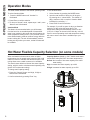
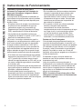
Operating Instructions
Water Heater Capacity and Increasing Temperature
Setpoint (For Water Heaters without an Integrated
Mixing Valve):
The water heater temperature setting strongly impacts
the amount of usable hot water available for showers
and baths.
• Energy consumption/savings and efficiency testing of
water heaters is performed according to Department
of Energy (DOE) requirements specified at the date of
manufacture.
• Safety regulations require a factory setting no greater
than 125°F (52°C) for all new water heaters. Therefore,
if your old water heater was set to a hotter temperature
than your new water heater with a factory set setpoint of
120°F (49°C), the new water heater may seem to provide
lower capacity than your old water heater. This can be
corrected by increasing the temperature setpoint.
• If more hot water capacity is desired, increasing the
temperature from 120°F to 135°F (49°C to 57°C) will
enable the same tank of hot water to last about 25%
longer because less hot water is mixed in at the shower
or faucet.
• Increasing the water temperature setpoint may improve
the cleaning performance of dishwashers and washing
machines.
• The user can adjust the temperature setting to meet
their needs. Always read and understand the safety
instructions contained in the owner’s manual before
adjusting the temperature setpoint.
Mixing Valves
• For models with an integrated electronic mixing valve,
hot water capacity can be increased by changing
capacity selection from control, while maintaining
outlet water temperature. See page 8 for instructions
to increase hot water capacity.
• If your model does not include an integrated Electronic
mixing valve: a supplimental mixing valve for reducing
point-of-use water temperature by mixing hot and cold
water in branch water lines are commercially available.
Contact a licensed plumber or the local plumbing
authority for further information.
Extended Shutdown Periods
If the water heater is to remain idle for an extended
period of time, the power and water to the appliance
should be turned off and the water heater drained to
conserve energy and prevent a buildup of dangerous
hydrogen gas. This unit has no power button, power
can only be shut off at the circuit breaker or disconnect
switch.
The water heater and piping should be drained if they
might be subjected to freezing temperatures.
After a long shutdown period, the water heater’s
operation and controls should be checked by qualified
service personnel. Make certain the water heater is
completely filled again before placing it in operation.
NOTE: Refer to the Hydrogen Gas Caution in the
Operating Instructions (see page 3).
OPERATING INSTRUCTIONS

49-6000226 Rev. 4 7
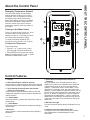
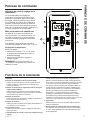
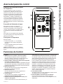
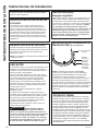
About the Control Panel
ABOUT THE CONTROL PANEL
Control Features
1. Display
2. Mode Select Button and Mode Indicator
Use this button to alternate between Normal and Vacation
modes. Enter key must be depressed to confirm selection.
3. Tank Capacity Selection Button and Indicator
Status (on some models)
Use this button to alternate between Normal, High and
X-High tank capacities. Enter key must be depressed to
confirm selection.
4. + Select Button
Use these buttons to increase the temperature setting or
vacation days.
5. - Select Button
Use these buttons to decrease the temperature setting or
vacation days.
6. Enter Key
Use this button to confirm temperature setting following
adjustment.
7. Anode Reset and Replacement Indicator (if
equipped)
When the Anode text is illuminated and F70 fault is
displayed, the system has indicated that the anode rod
is approaching end of life and it is recommended to
replace it. Press button once to silence alarm. Press
and hold for 5 seconds to reset the anode alarm after
replacing. Call the Installer to replace the anode rod. The
Servicer contact info is located next to the rating plate of
the unit, or contact GE Appliances customer support at
GEAppliances.com/waterheater. Failure to replace the
anode rod will void warranty coverage and may result in
a tank leak. (See page 12 for instructions to change the
anode rod.)
8. Wifi Indicator Light
Lit when connected, flashing during configuration set up
mode.
9. Appliance Communication Module Port
For use with Service and optional accessory modules.
Visit GEAppliances.com/waterheaters for more
information.
Displaying Temperature Setpoint
The
control will display the temperature
setpoint anytime a button on the control
is pressed. After 30 seconds of inactivity,
the display will go blank. Note that the
Mode and Capacity selection (if equipped)
will remain illuminated in sleep mode. To
wake the control at any time to see the
temperature setpoint, press any button on
the control.
Turning on the Water Heater
There is no power button for this unit. Once
the water heater is wired and power is
supplied, it will be on. The display will show
the current water temperature setting.
To comply with safety regulations, the
controls are factory preset to 120°F (49°C).
To Adjust the Temperature
Follow these steps:
1. Press the + or - button on the control
panel key pad to desired temperature.
2. Press ENTER to accept the new setting.
Note: To change between °F and °C, press
and hold the Mode Select button.
4
6
5
7
9
8
1
2
3

8 49-6000226 Rev. 4
Operation Modes
OPERATION MODES
This water heater defaults to the Normal operating mode.
To select Vacation Mode:
1. Press the MODE button until “Vacation” is
illuminated.
2. Press Enter to confirm selection.
3. To return to “Normal” mode, repeat steps 1 and 2, once
“Normal” text is illuminated.
Vacation Mode
This feature is recommended when you will be away
from the home for an extended period of time and hot
water is not needed. In this mode, the unit will reduce the
water temperature setting to 50ºF (10°C) and will use the
most efficient heating mode to conserve energy while the
heater is sitting idle. The unit will automatically resume
heating one day before your return, so that hot water will
be available.
To set Vacation Mode:
1. Select Vacation by pressing the MODE button.
2. Input the total number of days you will be gone
by pressing the +/- select button. The default is 7
days, maximum 199, or remain in Vacation Mode
indefinitely by selecting “---”.
3. Press Enter to confirm selection
For example, if you will be gone 14 days, set Vacation
mode for 14 days using the steps above. The
temperature setting will automatically reduce to 50
0
F
(10
0
C) for 13 days. At the end of the 13th day, unit will
return to normal operating mode and temperature setting
will reset to ensure hot water is available upon your
return.
When activated this feature stores water at higher
temperatures. As hot stored water leaves the tank, cold
water is mixed in to maintain the desired set point. This
mixing allows more usable hot water to be available.
The water heater defaults to Normal hot water Capacity
setting, which is used to calculate annual operating cost,
(and a 125F outlet water setting).
To change tank Capacity setting:.
1. Press the “Capacity” button until High, X-High or
Normal text is illuminated.
2. Confirm selection by pressing “Enter” key.
Capacity Options (based on 120°F default outlet water
temperature setting and 58°F inlet water temperature):
Normal: No increase of hot water capacity from outlet
water setting
High: Increases hot water capacity up to 40%
X-High: Increases hot water capacity up to 60%
Hot Water Flexible Capacity Selection (on some models)

49-6000226 Rev. 4 9
Appliance Communication
APPLIANCE COMMUNICATION
GE Appliances WiFi Connect (for customers in the United States)
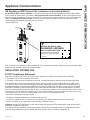
GE Appliances WiFi Connect Enabled*
If your water heater has a Connected Appliance Information label located
on the outside as shown below, your model is GE Appliances WiFi Connect Enabled. A WiFi communication card is
built into the product allowing it to communicate with your smart phone for remote monitoring, control and notifications.
Please visit GEAppliances.com/connect to learn more about connected appliance features, and to learn what
connected appliance apps will work with your smart phone.
*Select models only
Network: GE_Module_XXXX
PASSWORD: XXXXXXXX
MAC: XX-XX-XX-XX-XX-XX
CONTAINS FCCID: ZKJ-WCATA006
CONTAINS IC: 10229A-WCATA006
184D2604P001
WiFI Connectivity: For assistance with the appliance or the ConnectPlus network connectivity (for models that are WiFi
enabled or WiFi optional), please call 1-800-220-6899.
REGULATORY INFORMATION
FCC/IC Compliance Statement:
This device complies with Part 15 of the FCC Rules. Operation is subject to the following two conditions:
1. This device may not cause harmful interference.
2. This device must accept any interference received, including interference that may cause undesired operation.
This equipment has been tested and found to comply with the limits for a Class B digital device, pursuant to Part
15 of the FCC Rules. These limits are designed to provide reasonable protection against harmful interference in a
residential installation. This equipment generates uses and can radiate radio frequency energy and, if not installed
and used in accordance with the instructions, may cause harmful interference to radio communications. However,
there is no guarantee that interference will not occur in a particular installation. If this equipment does cause harmful
interference to radio or television reception, which can be determined by turning the equipment off and on, the user
is encouraged to try to correct the interference by one or more of the following measures:
• Reorient or relocate the receiving antenna.
• Increase the separation between the equipment and receiver.
• Connect the equipment into an outlet on a circuit different from that to which the receiver is connected.
• Consult the dealer or an experienced radio/television technician for help.
Labelling: Changes or modifications to this unit not expressly approved by the manufacturer could void the user’s
authority to operate the equipment.
This product has WiFi capability and requires Internet connectivity and a wireless router to enable interconnection
with an Energy Management System, and/or with other external devices, systems, or applications.

10 49-6000226 Rev. 4
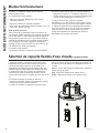
Routine Preventive Maintenance
DANGER
Risk of Scald - Before manually
operating the relief valve, make certain no one will
be exposed to the danger of coming in contact with
the hot water released by the valve. The water may
be hot enough to create a scald hazard. The water
should be released into a suitable drain to prevent
injury or property damage.
NOTE: If the temperature and pressure-relief valve
on the hot water heater discharges periodically, this
may be due to thermal expansion in a closed water
system. Contact the water supplier or your plumbing
contractor on how to correct this. Do not plug the
relief valve outlet.
Properly maintained, your water heater will provide years
of dependable trouble-free service. It is suggested that
the following annual preventive maintenance program be
established.
1. Inspect Temperature & Pressure Relief Valve.
2. Inspect heating elements, ECO, and wiring to each.
3. Drain and Flush the water heater tank.
4. Anode rod must be removed and inspected.
Temperature and Pressure-Relief Valve:
Once a year, it is recommended to lift and release the
lever handle on the temperature and pressure-relief
valve, located on the front-right side of the water heater,
to make certain the valve operates freely. Allow several
gallons to flush through the discharge line to an open
drain.
Heating Elements and ECO:
Once a year, it is recommended to inspect the heating
elements, ECO, and wiring to each. Inspection should
be completed by service personnel qualified in electrical
appliance repair.
Most electrical appliances, even when new, make some
sound when in operation. If the hissing or singing sound
level increases excessively, the electric heating element
may require cleaning. Contact a qualified installer or
plumber for inspection.
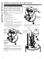
Draining and Flushing the Water Heater
CAUTION
Risk of Shock - Shut off power to
the water heater before draining water.
DANGER
Risk of Scald - Before manually
operating the relief valve, make certain no one will
be exposed to the hot water released by the valve.
The water drained from the tank may be hot enough
to present a scald hazard and should be directed to
a suitable drain to prevent injury or damage.
A water heater’s tank can act as a settling basin for
solids suspended in the water. It is therefore not
uncommon for hard water deposits to accumulate in the
bottom of the tank. To clean the tank of these deposits,
it is recommended to drain and flush the water heater
tank once a year. To drain the water heater, follow these
steps:
1. Turn off power to the unit. The electric heating
elements will become damaged if operated without
water.
2. Attach a garden hose to the drain valve located at the
bottom of the unit and direct that hose to a drain.
3. Turn off the cold water supply.
4. Admit air to the tank by opening a hot water faucet or
lifting the handle on the relief valve.
5. Open the drain valve.
Flushing the Tank:
1. Follow steps above to drain the water heater.
2. Once the water heater is empty, with the drain valve
open and garden hose attached to the drain valve,
turn on the cold water supply.
3. Allow several gallons to flush through the drain valve
and hose to an open drain.
4. Turn off the water supply and allow any water
remaining in the tank to drain.
5. Repeat steps 3 and 4 until water runs clear.
6. Close the drain valve and fill the tank before returning
power to the unit. The tank is full when water runs out
of a nearby open hot water faucet.
Flushing should be done with an empty tank to promote
additional removal of sediment.
Care and Cleaning
Exterior Surfaces
Hand wash with damp cloth, using only warm water. Wipe dry using a dry, clean cloth.
Use a flat blade screwdriver
to turn brass drain valve or an
adjustable open-end wrench to
turn black stem on plastic drain
valve.
Straight Brass
Drain Valve
CARE AND CLEANING

49-6000226 Rev. 4 11
CARE AND CLEANING
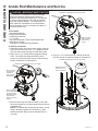
Anode Rod
Anode rods are designed and installed to protect and
extend the life of residential water storage tanks.
The anode rod must be removed from the water heater’s
tank and inspected annually, and replaced when more
than 6” (15.2 cm) of core wire is exposed at either end of
the rod.* NOTE: Artificially softened water will cause the
anode rod to consume more rapidly.
Due to shock hazard and to prevent accidental water
leaks, this inspection should be done by a qualified
servicer or plumber, and requires that the electric power
and cold water supply be turned off before servicing the
anode rod.
NOTICE: Do not remove the anode rod from the water
heater’s tank except for inspection and/or replacement,
as operation with the anode rod removed will shorten
the life of the glass-lined tank and will void warranty
coverage.
Some areas have water conditions that may cause
an odor to develop in the water heater. Special alloy
replacement rods are available to address this condition.
*NOTE: Failure to replace the anode rod when
consumed voids the warranty for the tank. Warranty
coverage for all other components remains intact,
and is unaffected by this maintenance requirement.
The replacement anode rod, and the inspection for
consumption are not covered by warranty.
Additional information for models with an anode
depletion sensing feature (Anode button on the control,
on equipped models):
When the depletion-sensing anode rod nears end of life,
the ANODE text will illuminate and the control will beep
and display F70. When this occurs, the anode rod must
be inspected and replaced if the core wire at the top of
the anode rod is exposed.* It is recommended to replace
the anode rod as soon as possible to ensure that the tank
will continue to be protected from corrosion. Call installer/
servicer to order or to replace the anode rod. (See page 12
for instructions to change the anode rod.)
Press the ANODE button once to silence the alarm. Once
replaced, reset the alarm by pressing and holding the
ANODE button for 5 seconds until the control beeps and the
Anode Light will turn off.
If special alloy anode rod is installed to address a water
odor condition, the anode depletion sensing feature must
be disabled. If disabled, annual inspections of the anode
rod are required since the water heater will no longer be
capable of alerting for a depleted anode rod.
To disable the feature:
1. Upon power-up following a special alloy anode rod
installation, the control will sound an alarm and F41 will
display. Press the ANODE button to quiet the alarm.
2. Press the ANODE button 3 times. “Off” or “On” will
display confirming that the feature has been disabled/
enabled.
To enable the feature if a new anode depletion sensing
anode rod is installed, follow Step 2 above.
Note: If the display is blank, press any button to wake the
control before entering a button combination.
NOTE: If the water heater has been installed with a
device that periodically cuts power to the water heater, the
accuracy of the anode rod depletion sensing feature may
become compromised and anode rod inspection every 2-3
years is required.
If the water heater will be inactive for a long period of time
and the water heater cannot be drained, it is recommended
to leave the power turned on with the water heater in
vacation mode to ensure that the feature will continue to
operate properly while still conserving energy.
NOTE: Refer to the Hydrogen Gas Caution in the
Operating Instructions (see page 3).
Care and Cleaning
Routine Preventative Maintenance

12 49-6000226 Rev. 4
Tools needed:
• Flat Head Screwdriver
• Phillips head screwdriver
• Socket/Torque Wrench
• 1
1
/16” Socket
• Pipe Joint Compound or Pipe Thread Sealant Tape
• Anode Rod, if needed
* See page 22 for part ordering instructions
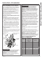
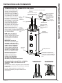
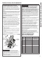
To Service Anode Rod:
1. Disconnect power, shut off the water supply, drain the
water lines of the home. Drain 1 to 2 gallons of water
from the water heater through the lower drain valve.
2. Skip to step 3, for models without Integrated Mixing
Valve. For models with Integrated Mixing Valve,
remove (4) screws and front section of shroud using
Phillips screwdriver per Illustration B.
3. Remove anode cap and foam insulation in hole with
flat head screwdriver to expose anode fitting as shown
in illustration B.
NOTE: For models with sensing anode feature, anode
fitting is already exposed (see illustration C). Wire
attached to anode fitting must be detached prior to
next step.
4. Using a 1 1/16” socket/wrench, unscrew the anode
rod, then lift out to inspect as shown in illustration D.
Anode Rod Maintenance and Service
CAUTION - IMPORTANT SAFETY NOTICE
This information is intended for use by individuals
possessing adequate background of electrical,
electronic and mechanical experience. Any attempt
to repair a major appliance may result in personal
injury and property damage. The manufacturer or
seller cannot be responsible for the interpretation
of this information, nor can it assume any liability in
connection with its use.
Illustration B (Appearance will vary by model)
Illustration C (Appearance will vary by model)
Illustration D (Appearance will vary by model)
Remove anode
cap and foam
insulation in
hole to expose
anode fitting
Remove (4) phillips
screws (if equipped)
on front shroud on
integrated mixing
valve model to
expose anode rod
aceess.
Remove anode
wire if equiped
with sensing
anode.
Replace anode rod
if more than 6” of
core wire exposed
CARE AND CLEANING

49-6000226 Rev. 4 13
CARE AND CLEANING
5. Replace Anode Rod (with same anode type that was
removed — sensing vs. standard), if more than 6” of
core wire is exposed. Contact Installer/Servicer for
correct replacement anode or GEA Customer Support
at GEAppliances.com/waterheater.
6. To Install anode rod:
a. Seal the threads with pipe joint compound or pipe
thread sealant tape.
b. Thread into the port and tighten with torque wrench
to 50 +/- 5 ft-lbs of torque.
7. Turn water supply on, open a tap to remove any
trapped air in water lines and inspect for leaks. Repair
any leaks, prior to proceeding.
8. Reconnect wire to anode fitting (for anode depleteion
sensing models) or replace anode cap (for standard
non-sensing anode)
9. Reassemble front shroud, previously removed in step
2, if equipped.
10. Turn power On. If sensing anode was replaced with
a special alloy (non-sensing) anode rod, the anode
depletion sensing feature must be disabled and the
unattached wire end must be covered with electrical
tape. See page 12 for instructions on enabling or
disabling sensing anode.
11. Reset ANODE replacement indicator light (if
equipped) by pressing and holding ANODE button for
10 seconds to indicate that a new anode depletion
sensing anode rod is installed.
Anode Rod Maintenance and Service

14 49-6000226 Rev. 4
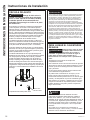
Installation Instructions
INSTALLATION INSTRUCTIONS
The location chosen for the water heater must take
into consideration the following:
LOCAL INSTALLATION
REGULATIONS
This water heater must be installed in accordance
with these instructions, local codes, utility codes,
utility company requirements or, in the absence of
local codes, the latest edition of the National Electrical
Code. It is available from some local libraries or
can be purchased from the National Fire Prevention
Association, Batterymarch park, Quincy, MA 02169 as
booklet ANSI/NFPA 70.
POWER REQUIREMENTS
Check the markings on the rating plate of the water
heater to be certain the power supply corresponds
to the water heater requirements. NOTE: 208V
installations may experience lower performance.
LOCATION
The water heater and water lines should be protected
from freezing temperatures and high-corrosive
atmospheres. Do not install the water heater in outdoor,
unprotected areas.
Locate the water heater in a clean dry area as near as
practical to the area of greatest heated water demand.
Long uninsulated hot water lines can waste energy
and water. Unit must be installed in a level location.
If required, add shims under base of unit to level for
proper operation.
NOTE: This unit is designed for any common indoor
installation.
Servicing the water heater requires proper installation
such that front panels can be removed to permit
inspection and servicing. Reference installation
instructions found in this manual.
Moving the water heater or other appliances to provide
service to the water heater is not covered under
warranty.
CAUTION
Risk of Property Damage -
The water heater should not be located in an
area where leakage of the tank or connections
will result in damage to the area adjacent to it
or to lower floors of the structure. Where such
areas cannot be avoided, it is recommended
that a suitable catch pan, adequately drained, be
installed under the water heater.
LOCATION (Cont).
Required clearances:
There must be sufficient clearance between any
object and the top, rear and sides of the water
heater in the event service is needed. The controls
and drain at front of unit must have clear access
for operation and service. Installations that require
minimal clearance on the sides or rear of the water
heater for earthquake straps are also acceptable.
In these cases, additional clearance should be
provided on the opposite side of the unit to
allow for service access. Integrated electronic
mixing valve models should not be installed
with pre-heated water from solar or other heated
sources (higher than intended user set point).
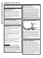
CATCH PAN INSTALLATION
(If required)
NOTE: Auxiliary catch pan MUST conform to local
codes. Catch Pan Kits are available from the store
where the water heater was purchased, a builder
store or any water heater distributor. The catch
pan should be 2” (5.1 cm) minimum larger than the
Water Heater base diameter. To prevent corrosion
and improve Drain Valve access it is recommended
that the water heater be placed on spacers inside
the catch pan.
Relief Valve
Drain Line
Catch Pan
Catch Pan
Drain (piped to
suitable drain)
THERMAL EXPANSION
If a check valve is present on the inlet water line,
it will create a “closed system.” Heating water in
a closed system creates an increase in pressure
within the water system because the pressure is not
able to dissipate in the main supply line. Referred to
as “thermal expansion”, the rapid pressure increase
can cause the relief valve to operate (releasing
water) during each heating cycle, potentially causing
premature failure to the valve or even the water
heater. The suggested method of controlling thermal
expansion is to install an expansion tank in the cold
water line between the water heater and the check
valve as shown in the following illustrations. Contact
your installing contractor, water supplier, or plumbing
inspector for additional information.

49-6000226 Rev. 4 15
Installation Instructions
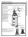
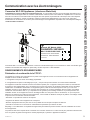
WATER SUPPLY CONNECTIONS
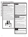
Refer to the illustration below for recommended installation. The HOT and COLD water connections are clearly
marked and are ¾” NPT on all models. When connecting to the inlet/outlet ports, the use of ¾” female NPT
tapered thread fittings with use of thread sealant is recommended. The installation of unions is recommended
on the hot and cold water
connections so that the
water heater may be easily
disconnected for servicing if
necessary. Piping should be
routed to allow anode rod
removal.
NOTE: Install a shut-off valve
in the cold water line near the
water heater. This will enable
easier service or maintenance
of the unit later.
IMPORTANT: Do not apply
heat to the HOT or COLD
water connections. If sweat
connections are used, sweat
tubing to adapter before
fitting the adapter to the cold
water connections on heater.
Any heat applied to the hot
or cold water connection
will permanently damage
the internal plastic lining in
these ports.
Install a vacuum relief valve
and/or anti-siphon device when
required by local jurisdictions.
HOT AND COLD PIPE INSULATION INSTALLATION (if
supplied with product)
For increased energy efficiency, some water heaters have
been supplied with two 24” sections of pipe insulation.
Please install the insulation, according to the illustrations
below, that best meets your requirements.
INSTALLATION INSTRUCTIONS
Typical vertical
piping arrangement
Typical horizontal
piping arrangement
Illustration E (Appearance will vary by model)
Hot water
outlet to
fixtures
Unions
Water Heater
Electrical
Junction Box
Temperature
and Pressure
Relief Valve
Integrated
Electronic Mixing
Valve Shroud (if
Equipped)
Shut-off valve
Conduit to Electrical
Junction Box (use only
copper conductors)
Thermal expansion
tank (Install per
manufacturer’s
instructions, if required.)
Drain Valve Catch Pan
Relief Valve discharge within 6” of
floor and no closer than 2 times the
pipe diameter per local code.
Cold Water Supply

16 49-6000226 Rev. 4
Installation Instructions
TO FILL THE WATER HEATER
WARNING
Risk of Unit Damage - The
tank must be full of water before heater is turned
on. The water heater warranty does not cover
damage or failure resulting from operation with
an empty or partially empty tank.
Make certain the drain valve is completely closed.
Open the shut-off valve in the cold water supply line.
Open each hot water faucet slowly to allow the air to
vent from the water heater and piping.
A steady flow of water from the hot water faucet(s)
indicates a full water heater.
Condensation can form on the tank and fittings when
it is first filled with water. Condensation may also
occur with a heavy water draw and very cold inlet
water temperature.
This condition is not unusual and will disappear once
water is heated. If condition persists, examine fittings
for potential leaks and repair, as required.
NOTICE
Do not mis-wire electrical connections. 240VAC or
208VAC must be applied across L1 and L2 wires as
shown in ‘Water heater junction box’ illustration.
If a 4-conductor wire is supplied to the water heater,
cap the neutral, and connect the remaining wires as
illustrated.
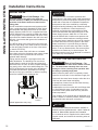
RELIEF VALVE
WARNING
Risk of Unit Damage - The
pressure rating of the relief valve must not
exceed 150 PSI (1.03 MPa), the maximum working
pressure of the water heater as marked on the
rating plate.
A new combination temperature and pressure-relief
valve, complying with the Standard for Relief Valves
and Automatic Gas Shut-Off Devices for Hot Water
Supply Systems, ANSI Z21.22, is supplied and must
remain installed in the opening provided and marked
for this purpose on the water heater. No valve of any
type should be installed between the relief valve and
the tank. Local codes shall govern the installation of
relief valves.
The BTUH rating of the relief valve must not be less
than the input rating of the water heater as indicated
on the rating label located on the front of the heater
(1 watt=3.412 BTUH).
Connect the outlet of the relief valve to a suitable
open drain so that the discharge water cannot contact
live electrical parts or persons and to eliminate
potential water damage.
Piping used should be of a type approved for hot
water distribution. The discharge line must be no
smaller than the outlet of the valve and must pitch
downward from the valve to allow complete drainage
(by gravity) of the relief valve and discharge line. The
end of the discharge line should not be threaded or
concealed and should be protected from freezing.
No valve of any type, restriction or reducer coupling
should be installed in the discharge line.
(Model appearance may vary)
CAUTION
To reduce the risk of excessive pressures and
temperatures in this water heater, install temperature
and pressure protective equipment required by local
codes and no less than a combination temperature
and pressure relief valve certified by a nationally
recognized testing laboratory that maintains periodic
inspection of production of listed equipment or
materials, as meeting the requirements for Relief
Valves and Automatic Gas Shutoff Devices for Hot
Water Supply Systems, ANSI Z21.22. This valve
must be marked with a maximum set pressure not
to exceed the marked maximum working pressure
of the water heater. Install the valve into an opening
provided and marked for this purpose in the water
heater, and orient it or provide tubing so that any
discharge from the valve exits only within 6 inches
above, or at any distance below, the structural floor,
and does not contact any live electrical part. The
discharge opening must not be blocked or reduced in
size under any circumstances.
Relief Valve
Insulation
INSTALLATION INSTRUCTIONS

49-6000226 Rev. 4 17
INSTALLATION INSTRUCTIONS
Installation Instructions
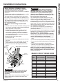
ELECTRICAL CONNECTIONS
A separate branch circuit with copper conductors,
overcurrent protective device and suitable
disconnecting means must be provided by a qualified
electrician.
All wiring must conform to local codes or latest edition
of National Electrical Code ANSI/NFPA 70.
The water heater is completely wired to the junction
box at the top of the water heater. An opening for 1/2”
electrical fitting is provided for field wiring connections.
The voltage requirements and wattage load for the
water heater are specified on the rating label on the
front of the water heater.
The branch circuit wiring should include
either:
1. Metallic conduit or metallic sheathed cable approved
for use as a grounding conductor and installed with
fittings approved for the purpose.
2. Nonmetallic sheathed cable, metallic conduit or
metallic sheathed cable not approved for use
as a ground conductor shall include a separate
conductor for grounding. It should be attached to
the ground terminals of the water heater and the
electrical distribution box.
To connect power to the water heater:
1. Turn the power off.
2. Remove the screw/screws holding the junction box
top cover.
3. Install L1 to L1, L2 to L2 and ground wire onto the
fixed junction box cover, per illustration below.
4. Reconnect all screws attaching the junction box
covers.
WARNING
Risk of fire or electrical shock.
Ensure both junction box covers and ground
screws are securely fastened for proper
grounding.
NOTE: Install electric connections according to local
codes or latest edition of National Electrical Code
ANSI/NFPA 70.
WARNING
Proper ground connection is
essential. The presence of water in the piping
and water heater does not provide sufficient
conduction for a ground. Nonmetallic piping,
dielectric unions, flexible connectors, etc., can
cause the water heater to be electrically isolated.
Do not disconnect factory ground.
The manufacturer’s warranty does not cover any
damage or defect caused by installation, attachment
or use of any type of energy-saving or other
unapproved devices (other than those authorized by
the manufacturer) into, onto or in conjunction with the
water heater. The use of unauthorized energy-saving
devices may shorten the life of the water heater and
may endanger life and property.
The manufacturer disclaims any responsibility for
such loss or injury resulting from the use of such
unauthorized devices.
If local codes require external application of insulation
blanket kits, the manufacturer’s instructions included
with the kit must be carefully followed.
Application of any external insulation, blankets
or water pipe insulation to this water heater will
require careful attention to the following:
• Do not cover the temperature and pressure-relief
valve.
• Do not cover access panels to the heating elements.
• Do not cover the electrical junction box of the water
heater.
• Do not cover the operating or warning labels
attached to the water heater or attempt to relocate
them on the exterior of the insulation blanket.
NOTE: This guide recommends minimum branch
circuit sizing based on the National Electric Code.
Refer to wiring diagrams in this manual for field
wiring connections.
BRANCH CIRCUIT SIZING GUIDE
Total
Water
Heater
Wattage
Recommended Over-
Current Protection
(fuse or circuit breaker
amperage rating)
Copper Wire Size AWG
Basedon N.E.C. Table
310-16 (167°F/75°C.)
@240V 208-240V 208-240V
3,000 20 12
4,000 25 10
4,500 25 10
5,000 30 10
5,500 30 10
6,000 35 8
8,000 45 8
9,000 50 8
10,000 – –
11,000 – –
12,000 – –
Junction
Box Cover
Junction
Box Cover
House
Ground
(Green)
Water Heater Junction Box
L1
(Black)
Factory Ground
L2
(Red)

18 49-6000226 Rev. 4
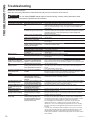
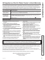
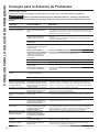
Troubleshooting
Before you call for service....
Save time and money! Review the chart below first and you may not need to call for service.
CAUTION
For your safety, DO NOT attempt repair of electrical wiring, controls, heating elements or other
safety devices. Refer repairs to qualified service personnel.
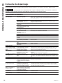
Problem Possible Causes What To do
OPERATION AND PERFORMANCE
Not enough or no hot water Water temperature may be set too
low
• See the Water Temperature Adjustment and Water Heater
Capacity sections (see pages 4 and 6). If the product has an integrated mixing
valve, turn capacity setting up to “High” or “X-High” to increase available hot
water capacity.
Cold water inlet temperature may
be colder during the winter months
•
This is normal. The colder inlet water takes longer to heat.
• Consider increasing the set temperature as described in the Water Temperature
Adjustment section or increase capacity setting on models equipped with
electronic mixing valve.
Leaking or open hot water faucets • Make sure all faucets are closed.
Long runs of exposed pipe, or hot
water piping on outside wall
• Insulate piping.
Dip tube damaged • Contact your local installer, plumbing contractor, or previously agreed upon
service agency.
A fuse is blown, circuit breaker
tripped, or electric service to your
home may be interrupted
• Replace fuse or reset circuit breaker.
• Contact the local electric utility.
Inadequate wiring • See the Installation Instructions.
Manual reset high limit (ECO) • See the Safety Controls section, see page 5.
Water Connections to unit reversed • Correct piping connections.
Recirculating System Interference
(if installed)
• Check flow rate is not set too high.
• Insulate piping
Water is too hot Water temperature is set too high • See the Water Temperature Adjustment section.
Electronic Control has failed
• Contact your local installer, plumbing contractor, or previously agreed upon
service agency.
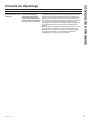
Control Panel
The heater is beeping, the
anode light is on (on some
models), and the display says
F70
The anode rod is approaching end
of life and it is recommended to
replace it in order to continue to
offer protection from corrosion.
• Call for service or follow the instructions on how to replace the anode rod on
page 12. Ensure that the anode depletion sensing anode rod or other GE
Appliances approved anode rod is installed. Installation of an unapproved anode
rod will VOID the warranty.
The heater is beeping and the
display says F41
The anode rod is not connected
properly and the water heater may
not be protected from corrosion.
• Check that the tank is filled completely with water.
• If the tank is full of water and the F41 code persists, contact GE Appliances
service.
• Press anode button to silence alarm.
The heater is beeping and the
screen flashes, F78.
Unit is not receiving 240VAC as
intended.
• Turn off power to water heater (generally at the breaker panel). Then read
Electrical Connections section of the installation Instructions, see page 17, then
contact the installer to verify electrical input to the water heater.
OTHER
Rumbling noise Water conditions in your home
caused a buildup of scale or
mineral deposits on the heating
elements
• Remove and clean the heating elements. This should only be done by a
qualified service person or plumbing contractor.
Squealing/Chirping sound
when drawing hot water
In certain usage conditions, noise
may transmit through plumbing
from the integrated mixing valve.
• Increasing user set point or lowering capacity setting may address this condition
on integrated mixing valve models. Consult a plumbing professional to install a
pressure limiting device, if due to high water pressure.
Intermittent EMV motor noise
on integrated mixing valve
models
A soft motor noise may be heard
during normal operation due to
movement of control valve.
• This noise is normal and does not indicate any issue with product
Water dripping down the
outside of the heater
Hot/Cold water connections or
other parts have loosened
•
Tighten the loose connections. This should only be done by a qualified service
person or plumbing contractor.
Relief valve producing
popping sound or draining
Pressure buildup caused by
thermal expansion to a closed
system
• This is an unacceptable condition and must be corrected. See Thermal
Expansion section on page 14. Do not plug the relief valve outlet. Contact a
plumbing contractor to correct this.
Hot water has a rotten egg or
sulfur smell
Certain water supplies with high
sulfate content will react with
the anode rod that is present in
all water heaters for corrosion
protection of the tank
• The odor can be reduced or eliminated in most water heaters by replacing
the anode rod with less-active material rod. In some cases, an added step of
chlorinating the water heater and all hot water lines may be necessary, contact
your local water professional or plumber for options and instructions.
Go to GEAppliances.com/waterheater for information on purchasing this
replacement anode rod. A qualified servicer or plumber should do this
replacement. Use of a non-GE Appliances approved anode rod, or operating
the water heater without a GE Appliances approved anode rod will VOID the
warranty.
• In certain cases, increasing the tank temperature to 140°F (60°C) can reduce
this odor issue. Reference the Water Temperature Adjustment section of the
Important Safety Information of this manual for procedure and dangers of
scalding water. Installation of temperature limiting valves can be used to reduce
risk of scalding.
TROUBLESHOOTING

49-6000226 Rev. 4 19
TROUBLESHOOTING
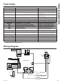
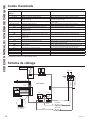
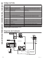
Fault Codes
Wiring Diagram
Fault Code Displayed Condition Action
F10 or F12 Lower Heating Element Failure Call Service to replace heating element
F11 or F13 Upper Heating Element Failure Call Service to replace heating Element
F16* Mixing Valve Outlet DC TCO Tripped Call Service to correct issue causing fault
and replace TCO.
F17 Missing jumper wire on non-EMV models Call Service to confirm issue and install
jumper wire plug.
F18*, F63* or F64* Mixing Valve Failure Call service to diagnose and repair
F19 Runaway Heat Source Call Service to repair
F30 Tank Temperature (T1) Failure open/short Call Service to replace sensor
F31 Tank Temperature (T2) Failure open/short Call Service to replace sensor
F32 or F33 Tank Temperature, (T1 or T2) Failure Call Service to replace required sensor
F38* Mixing Valve Outlet Temperature (T6) Failure Call Service to replace required sensor
F39* Mixing Valve Cold Inlet Temperature (T7) Failure Call Service to replace required sensor
F40 Current Sensor Failure Call Service to diagnose and correct
F41# Sensing Anode miswired Confirm wire is connected to sensing anode
terminal. Call Service otherwise.
F44 or F45 Micro Fault Call Service to repair
F70# Anode Depleted Call Service to replace sensing anode (see
anode replacement section in manual).
F71 AC Current Transformer Miswire Call Service to diagnose and repair
F76 Voltage too low Call Service for probable miswire
F77 Stuck Key Failure Call Service to diagnose and repair
F90 E2 module unplugged or damaged Call Service to diagnose and repair
F94 WiFi Board Failure (WiFi icon dark) Call Service to diagnose and repair
* Applies to models with integrated mixing valve
# Applies to models with sensing anode
TC01(ECO)
HI LIMIT
(180F)
1
2
3
4
1
11
L1 L2
UPPER ELEMENT
LOWER ELEMENT
5500W 10.5 ё ~22.9 A
5500W 10.5 ё ~22.9 A
M403
M401
•
NO
•
COM
M402
•
NO
•
COM
•
NC
K402
BLACK
RED
BLACK
BLUE
RED
BLUE
K401
••
•
•
•
•
•
•
•
•
•
•
•
•
•
T7
T6
MIXING
VALVE
TCO1
TCO1
AQUA
AQUA
RED
RED
ORANGE
AQUA
BROWN
YELLOW
RED
BLACK
BLACK
BLACK
BLACK
e2 Personality
module
J802
1
11
•
•
•
•
•
•
•
•
•
•
•
J802
J808
YELLOW
PURPLE
J801
•
•
•
•
•
•
T1
T2
BLUE
BLUE
RED
RED
6
1
•
•
ANODE
J807
•
GND
GREEN
RED
•
•
J301
WHITE
BLACK
SENSOR
•
•
J602
RED
WHITE
WIFI
MODULE
•
•
NAVY
BLUE
1
4
1
2
2
1
MAIN BOARD
J403
Non-EMV models: Use
J802 Jumper plug
(if equipped)
(if equipped)

20 49-6000226 Rev. 4
Notes
NOTES
La page est en cours de chargement...
La page est en cours de chargement...
La page est en cours de chargement...
La page est en cours de chargement...
La page est en cours de chargement...
La page est en cours de chargement...
La page est en cours de chargement...
La page est en cours de chargement...
La page est en cours de chargement...
La page est en cours de chargement...
La page est en cours de chargement...
La page est en cours de chargement...
La page est en cours de chargement...
La page est en cours de chargement...
La page est en cours de chargement...
La page est en cours de chargement...
La page est en cours de chargement...
La page est en cours de chargement...
La page est en cours de chargement...
La page est en cours de chargement...
La page est en cours de chargement...
La page est en cours de chargement...
La page est en cours de chargement...
La page est en cours de chargement...
La page est en cours de chargement...
La page est en cours de chargement...
La page est en cours de chargement...
La page est en cours de chargement...
La page est en cours de chargement...
La page est en cours de chargement...
La page est en cours de chargement...
La page est en cours de chargement...
La page est en cours de chargement...
La page est en cours de chargement...
La page est en cours de chargement...
La page est en cours de chargement...
La page est en cours de chargement...
La page est en cours de chargement...
La page est en cours de chargement...
La page est en cours de chargement...
La page est en cours de chargement...
La page est en cours de chargement...
La page est en cours de chargement...
La page est en cours de chargement...
La page est en cours de chargement...
La page est en cours de chargement...
La page est en cours de chargement...
La page est en cours de chargement...
-
 1
1
-
 2
2
-
 3
3
-
 4
4
-
 5
5
-
 6
6
-
 7
7
-
 8
8
-
 9
9
-
 10
10
-
 11
11
-
 12
12
-
 13
13
-
 14
14
-
 15
15
-
 16
16
-
 17
17
-
 18
18
-
 19
19
-
 20
20
-
 21
21
-
 22
22
-
 23
23
-
 24
24
-
 25
25
-
 26
26
-
 27
27
-
 28
28
-
 29
29
-
 30
30
-
 31
31
-
 32
32
-
 33
33
-
 34
34
-
 35
35
-
 36
36
-
 37
37
-
 38
38
-
 39
39
-
 40
40
-
 41
41
-
 42
42
-
 43
43
-
 44
44
-
 45
45
-
 46
46
-
 47
47
-
 48
48
-
 49
49
-
 50
50
-
 51
51
-
 52
52
-
 53
53
-
 54
54
-
 55
55
-
 56
56
-
 57
57
-
 58
58
-
 59
59
-
 60
60
-
 61
61
-
 62
62
-
 63
63
-
 64
64
-
 65
65
-
 66
66
-
 67
67
-
 68
68


dans d''autres langues
- English: GE GE30S10BLM User guide
- español: GE GE30S10BLM Guía del usuario
Documents connexes
-
GE RE2H80R6-1NCWW Le manuel du propriétaire
-
GE GeoSpring GEH50DXSRGA Owner's Manual & Installation Instructions
-
-
GE GE30S08BAM Le manuel du propriétaire
-
GE GE50T12BLM Manuel utilisateur
-
-
-
Autres documents
-
 GE Appliances GE30T12BLM Le manuel du propriétaire
-
Hotpoint-Ariston GL8Ti Le manuel du propriétaire
-
Bradford White RE2H50S10 Manuel utilisateur
-
GE Appliances Standard Electronic and Integrated Electronic Mixing Valve Water Heaters Mode d'emploi
-
Haier QAWF01A Le manuel du propriétaire
-
Camco 8615817 Le manuel du propriétaire
-
HTW TERMO SMART PLUS Manuel utilisateur
-
Weil-McLain AquaLogic Manuel utilisateur
-
HME NEXEO|HDX Crew Communication Platform Guide d'installation
