RIDGID R4040S-FT3500-FT3508-FT7007-FT7001 Manuel utilisateur
- Catégorie
- Outils électroportatifs
- Taper
- Manuel utilisateur
Ce manuel convient également à

Cette scie a été conçue et fabriquée conformément aux
strictes normes de fiabilité, simplicité d’emploi et sécurité
d’utilisation. Correctement entretenu, cet outil vous donnera
des années de fonctionnement robuste et sans problème.
AVERTISSEMENT :
Pour réduire les risques de blessures, l’utilisateur
doit lire et veiller à bien comprendre le manuel
d’utilisation avant d’employer ce produit.
Su sierra ha sido diseñado y fabricado de conformidad con
nuestras estrictas normas para brindar fiabilidad, facilidad de
uso y seguridad para el operador. Con el debido cuidado, le
brindará muchos años de sólido funcionamiento y sin problemas.
ADVERTENCIA:
Para reducir el riesgo de lesiones, el usuario debe
leer y comprender el manual del operador antes
de usar este producto.
CONSERVER CE MANUEL POUR
FUTURE RÉFÉRENCE
GUARDE ESTE MANUAL PARA
FUTURAS CONSULTAS
SAVE THIS MANUAL FOR FUTURE REFERENCE
Your saw has been engineered and manufactured to our high standard for dependability, ease of operation, and operator
safety. When properly cared for, it will give you years of rugged, trouble-free performance.
WARNING:
To reduce the risk of injury, the user must read and understand the operator’s manual before using this product.
OPERATOR’S MANUAL
MANUEL D’UTILISATION
MANUAL DEL OPERADOR
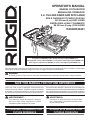
8 in. TILE AND PAVER SAW WITH LASER
SCIE À CARREAUX ET PAVES SOUS EAU
DE 203 mm (8 po) AVEC LASER
SIERRA PARA LOSAS Y PAVIMENTO
DE 203 mm (8 pulg.) CON LÁSER
R4040/R40401
To register your RIDGID product, please visit: http://register.RIDGID.com
Pour enregistrer votre produit de RIDGID, s’il vous plaît la visite: http://register.RIDGID.com
Para registrar su producto de RIDGID, por favor visita: http://register.RIDGID.com

2 — English
Introduction ......................................................................................................................................................................2
Introduction / Introducción
General Safety Rules .....................................................................................................................................................3-4
Règles de sécurité générales / Reglas de seguridad generales
Specific Safety Rules ........................................................................................................................................................ 4
Règles de sécurité particulières / Reglas de seguridad específicas
Symbols ............................................................................................................................................................................ 5
Symboles / Símbolos
Electrical ........................................................................................................................................................................6-7
Caractéristiques électriques / Aspectos eléctricos
Features .........................................................................................................................................................................8-9
Caractéristiques / Características
Tools Needed .................................................................................................................................................................... 9
Outils nécessaires / Herramientas necesarias
Loose Parts .................................................................................................................................................................... 10
Pièces détachées / Piezas sueltas
Assembly ...................................................................................................................................................................11-17
Assemblage / Armado
Operation ................................................................................................................................................................... 17-24
Utilisation / Funcionamiento
Adjustments ...............................................................................................................................................................25-28
Réglages / Ajustes
Maintenance ..............................................................................................................................................................29-30
Entretien / Mantenimiento
Warranty ......................................................................................................................................................................... 31
Garantie / Garantía
Parts Ordering and Service ...............................................................................................................................Back page
Commande de pièces et réparation / Pedidos de piezas y servicio
INTRODUCTION
INTRODUCTION / INTRODUCCIÓN
This product has many features for making its use more pleasant and enjoyable. Safety, performance, and dependability
have been given top priority in the design of this product making it easy to maintain and operate.
* * *
Ce produit offre de nombreuses fonctions destinées à rendre son utilisation plus plaisante et satisfaisante. Lors de la
conception de ce produit, l’accent a été mis sur la sécurité, les performances et la fiabilité, afin d’en faire un outil facile à
utiliser et à entretenir.
* * *
Este producto ofrece numerosas características para hacer más agradable y placentero su uso. En el diseño de este producto
se ha conferido prioridad a la seguridad, el desempeño y la fiabilidad, por lo cual se facilita su manejo y mantenimiento.
TABLE OF CONTENTS
TABLE DES MATIÈRES / ÌNDICE DE CONTENIDO

3 — English
GENERAL SAFETY RULES
WARNING:
Read and understand all instructions. Failure to
follow all instructions listed below, may result in
electric shock, fire and/or serious personal injury.
READ ALL INSTRUCTIONS
KNOW YOUR POWER TOOL. Read the operator’s manual
carefully. Learn the saw’s applications and limitations as
well as the specific potential hazards related to this tool.
GUARD AGAINST ELECTRICAL SHOCK BY
PREVENTING BODY CONTACT WITH GROUNDED
SURFACES. For example, pipes, radiators, ranges,
refrigerator enclosures.
KEEP GUARDS IN PLACE and in good working order.
REMOVE ADJUSTING KEYS AND WRENCHES. Form
habit of checking to see that keys and adjusting wrenches
are removed from tool before turning it on.
KEEP WORK AREA CLEAN. Cluttered areas and benches
invite accidents. DO NOT leave tools or pieces of tile on
the saw while it is in operation.
DO NOT USE IN DANGEROUS ENVIRONMENTS. Do
not use power tools in damp or wet locations or expose
to rain. Keep the work area well lit.
KEEP CHILDREN AND VISITORS AWAY. All visitors
should wear safety glasses and be kept a safe distance
from work area. Do not let visitors contact tool or extension
cord while operating.
MAKE WORKSHOP CHILDPROOF with padlocks and
master switches, or by removing starter keys.
DON’T FORCE TOOL. It will do the job better and safer
at the feed rate for which it was designed.
USE RIGHT TOOL. Don’t force the tool or attachment to
do a job it was not designed for. Don’t use it for a purpose
not intended.
USE THE PROPER EXTENSION CORD. Make sure
your extension cord is in good condition. Use only a
cord heavy enough to carry the current your product
will draw. An undersized cord will cause a drop in line
voltage resulting in loss of power and overheating. A wire
gauge size (A.W.G.) of at least 14 is recommended for an
extension cord 25 feet or less in length. If in doubt, use
the next heavier gauge. The smaller the gauge number,
the heavier the cord.
DRESS PROPERLY. Do not wear loose clothing, gloves,
neckties, or jewelry. They can get caught and draw you
into moving parts. Rubber gloves and nonskid footwear
(rubber soled boots) are recommended when working
outdoors. Also wear protective hair covering to contain
long hair.
ALWAYS WEAR EYE PROTECTION WITH SIDE
SHIELDS WHICH IS MARKED TO COMPLY WITH ANSI
Z87.1 WHEN USING THIS PRODUCT.
SECURE WORK. Use clamps or a vise to hold work when
practical, it is safer than using your hand and frees both
hands to operate the tool.
DON’T OVERREACH. Keep proper footing and balance
at all times.
MAINTAIN TOOLS WITH CARE. Keep tools sharp and
clean for better and safer performance. Follow instructions
for lubricating and changing accessories.
DISCONNECT TOOLS. When not in use, before servicing,
or when changing attachments, wheels, bits, cutters, etc.,
all tools should be disconnected.
AVOID ACCIDENTAL STARTING. Be sure switch is off
when plugging in any tool.
USE RECOMMENDED ACCESSORIES. Consult the
operator’s manual for recommended accessories. The
use of improper accessories may risk injury.
NEVER STAND ON TOOL. Serious injury could occur if
the tool is tipped or if the cutting tool is unintentionally
contacted.
CHECK DAMAGED PARTS. Before further use of the
tool, a guard or other part that is damaged should be
carefully checked to determine that it will operate properly
and perform its intended function. Check for alignment
of moving parts, binding of moving parts, breakage of
parts, mounting and any other conditions that may affect
its operation. A guard or other part that is damaged must
be properly repaired or replaced by an authorized service
center to avoid risk of personal injury.
USE THE RIGHT DIRECTION OF FEED. Feed work into
a wheel or cutter against the direction of rotation of wheel
or cutter only.
NEVER LEAVE TOOL RUNNING UNATTENDED. TURN
THE POWER OFF. Don’t leave tool until it comes to a
complete stop.
PROTECT YOUR LUNGS. Wear a face or dust mask if
the cutting operation is dusty.
PROTECT YOUR HEARING. Wear hearing protection
during extended periods of operation.
DO NOT ABUSE CORD. Never carry tool by the cord or
yank it to disconnect from receptacle. Keep cord from
heat, oil, and sharp edges.
ALWAYS USE AN OUTDOOR EXTENSION CORD
MARKED “W-A” OR “W”. These cords are rated for
outdoor use and reduce the risk of electric shock.
ALWAYS KEEP THE WHEEL GUARD IN PLACE and in
working order.
KEEP HANDS AWAY FROM CUTTING AREA. Keep
hands away from wheels. Do not reach underneathwork
or around or over the wheel while wheel is rotating. Do not
attempt to remove cut material when wheel is moving.
WHEEL COASTS AFTER BEING TURNED OFF.

4 — English
GENERAL SAFETY RULES
NEVER USE IN AN EXPLOSIVE ATMOSPHERE. Normal
sparking of the motor could ignite fumes.
INSPECT TOOL CORDS PERIODICALLY. If damaged,
have repaired by a qualified service technician at an
authorized service facility. The conductor with insulation
having an outer surface that is green with or without yellow
stripes is the equipment-grounding conductor. If repair
or replacement of the electric cord or plug is necessary,
do not connect the equipment-grounding conductor to a
live terminal. Repair or replace a damaged or worn cord
immediately. Stay constantly aware of cord location and
keep it well away from the rotating wheel.
INSPECT EXTENSION CORDS PERIODICALLY and
replace if damaged.
GROUND ALL TOOLS. If tool is equipped with three-
prong plug, it should be plugged into a three-hole
electrical receptacle.
ONLY POWER THE TOOL WITH A GFCI (GROUND
FAULT CIRCUIT INTERRUPTOR) PROTECTED
OUTLET.
CHECK WITH A QUALIFIED ELECTRICIAN or service
personnel if the grounding instructions are not completely
understood or if in doubt as to whether the tool is properly
grounded.
USE ONLY CORRECT ELECTRICAL DEVICES: 3-wire
extension cords that have 3-prong grounding plugs and
3-pole receptacles that accept the tool’s plug.
DO NOT MODIFY the plug provided. If it will not fit the
outlet, have the proper outlet installed by a qualified
electrician.
KEEP TOOL DRY, CLEAN, AND FREE FROM OIL AND
GREASE. Always use a clean cloth when cleaning. Never
use brake fluids, gasoline, petroleum-based products, or
any solvents to clean tool.
STAY ALERT AND EXERCISE CONTROL. Watch what
you are doing and use common sense. Do not operate
tool when you are tired. Do not rush.
DO NOT USE TOOL IF SWITCH DOES NOT TURN IT
ON AND OFF. Have defective switches replaced by an
authorized service center.
USE ONLY CORRECT WHEELS. Do not use wheels with
incorrect size holes. Never use washers or arbor nuts that
are defective or incorrect. The maximum wheel capacity
of your saw is 8 in. (203 mm).
BEFORE MAKING A CUT, BE SURE ALL ADJUSTMENTS
ARE SECURE.
NEVER TOUCH WHEEL or other moving parts during
use.
NEVER START A TOOL WHEN ANY ROTATING
COMPONENT IS IN CONTACT WITH THE WORKPIECE.
DO NOT OPERATE A TOOL WHILE UNDER THE
INFLUENCE OF DRUGS, ALCOHOL, OR ANY
MEDICATION.
WHEN SERVICING use only identical replacement parts.
Use of any other parts may create a hazard or cause
product damage.
USE ONLY RECOMMENDED ACCESSORIES listed in
this manual or addendums. Use of accessories that are not
listed may cause the risk of personal injury. Instructions for
safe use of accessories are included with the accessory.
DOUBLE CHECK ALL SETUPS. Make sure wheel is tight
and not making contact with saw or workpiece before
connecting to power supply.
SECURE WORK firmly against the miter guide or fence.
NEVER stand or have any part of your body in line with
the path of the wheel.
NEVER attempt to free a stalled wheel without first turning
the saw OFF and disconnecting the saw from the power
source.
IF THE POWER SUPPLY CORD IS DAMAGED, it must
be replaced only by the manufacturer or by an authorized
service center to avoid risk.
AVOID AWKWARD OPERATIONS AND HAND
POSITIONS where a sudden slip could cause your hand
to move into the cutting tool.
MAKE SURE THE WORK AREA HAS AMPLE LIGHTING
to see the work and that no obstructions will interfere with
safe operation BEFORE performing any work using the
saw.
ALWAYS TURN OFF SAW before disconnecting it, to
avoid accidental starting when reconnecting to power
supply.
THIS TOOL should have the following markings:
a) Wear eye, hearing, and breathing protection.
b) Use wheel guard for every operation for which it can
be used.
c) Disconnect saw before servicing, when changing
cutting wheels, and cleaning.
d) Use tool only with smooth edge cutting wheels free
of openings, grooves, and teeth.
e) Replace damaged cutting wheel before operating.
f) Do not fill water bath above water fill line.
SAVE THESE INSTRUCTIONS. Refer to them frequently
and use to instruct other users. If you loan someone
this tool, loan them these instructions too.
SPECIFIC SAFETY RULES

5 — English
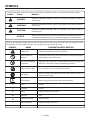
SYMBOLS
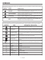
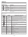
Some of the following symbols may be used on this product. Please study them and learn their meaning. Proper
interpretation of these symbols will allow you to operate the product better and safer.
SYMBOL NAME DESIGNATION/EXPLANATION
Safety Alert Indicates a potential personal injury hazard.
Read Operator’s
Manual
To reduce the risk of injury, user must read and understand operator’s
manual before using this product.
Eye, Ear, & Breathing
Protection
Always wear eye protection with side shields marked to comply with
ANSI Z87.1 along with hearing and breathing protection.
Wet Conditions Alert Do not expose to rain or use in damp locations.
No Hands
Failure to keep your hands away from the wheel will result in
serious personal injury.
Electrocution Failure to properly ground can result in electrocution.
V Volts Voltage
A Amperes Current
Hz Hertz Frequency (cycles per second)
min Minutes Time
Alternating Current Type of current
n
o
No-Load Speed Rotational speed, at no load
.../min Per Minute Revolutions, strokes, surface speed, orbits etc., per minute
The following signal words and meanings are intended to explain the levels of risk associated with this product.
SYMBOL SIGNAL MEANING
DANGER:
Indicates a hazardous situation, which, if not avoided, will result in death or
serious injury.
WARNING:
Indicates a hazardous situation, which, if not avoided, could result in death or
serious injury.
CAUTION:
Indicates a hazardous situation, that, if not avoided, may result in minor or
moderate injury.
NOTICE:
(Without Safety Alert Symbol) Indicates information considered important, but
not related to a potential injury (e.g. messages relating to property damage).

6 — English
ELECTRICAL
ELECTRICAL CONNECTION
This tool is powered by a precision built electric motor. It
should be connected to a power supply that is 120 V, AC
only (normal household current), 60 Hz. Do not operate
this tool on direct current (DC). A substantial voltage drop
will cause a loss of power and the motor will overheat. If the
saw does not operate when plugged into an outlet, double
check the power supply.
SPEED AND WIRING
The no-load speed of this tool is approximately 5,000 rpm.
This speed is not constant and decreases under a load or
with lower voltage. For voltage, the wiring in a shop is as
important as the motor’s horsepower rating. A line intended
only for lights cannot properly carry a power tool motor. Wire
that is heavy enough for a short distance will be too light for
a greater distance. A line that can support one power tool
may not be able to support two or three tools.
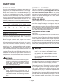
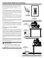
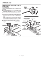
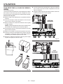
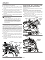
GROUNDING INSTRUCTIONS
See Figure 1.
This tool must be grounded. In the event of a malfunction or
breakdown, grounding provides a path of least resistance
for electric current to reduce the risk of electric shock. This
tool is equipped with an electric cord having an equipment-
grounding conductor and a grounding plug. The plug must be
plugged into a matching outlet that is properly installed and
grounded in accordance with all local codes and ordinances.
Do not modify the plug provided. If it will not fit the outlet,
have the proper outlet installed by a qualified electrician.
WARNING:
Improper installation of the grounding plug can
result in a risk of electric shock. When repair or
replacement of the cord is required, do not connect
the grounding wire to either flat blade terminal.
The wire with insulation having an outer surface
that is green with or without yellow stripes is the
grounding wire.
Check with a qualified electrician or service personnel if the
grounding instructions are not completely understood, or if
in doubt as to whether the tool is properly grounded.
Repair or replace a damaged or worn cord immediately.
This product is for use on a nominal 120 volt circuit and has
a grounding plug similar to the plug illustrated in figure 1.
Only connect the product to an outlet having the same
configuration as the plug. Do not use an adapter with this
product.
Ground Fault Circuit Interrupter (GFCI) protection should be
provided on the circuit(s) or outlet(s) to be used for the tile
saw. Outlets are available having built-in GFCI protection
and may be used for this measure of safety.
EXTENSION CORDS
Use only 3-wire extension cords that have 3-prong grounding
plugs and 3-pole receptacles that accept the tool’s plug.
When using a power tool at a considerable distance from
the power source, use an extension cord heavy enough
to carry the current that the tool will draw. An undersized
extension cord will cause a drop in line voltage, resulting in
a loss of power and causing the motor to overheat. Use the
chart provided below to determine the minimum wire size
required in an extension cord. Only round jacketed cords
listed by Underwriter’s Laboratories (UL) should be used.
**Ampere rating (on tool data plate)
0-2.0 2.1-3.4 3.5-5.0 5.1-7.0 7.1-12.0 12.1-16.0
Cord Length Wire Size (A.W.G.)
25' 16 16 16 16 14 14
50' 16 16 16 14 14 12
100' 16 16 14 12 10 —
**Used on 12 gauge - 20 amp circuit.
NOTE: AWG = American Wire Gauge
Always use an extension cord that is designed for outside
use. This is indicated by the letters “W-A” or “W” on the
cord’s jacket.
Before using an extension cord, inspect it for loose or
exposed wires and cut or worn insulation.
Use only extension cords that are intended for outdoor
use. These extension cords are identified by a marking
“Acceptable for use with outdoor appliances; store indoors
while not in use”. Use only extension cords having an
electrical rating not less than the rating of the product. Do
not use damaged extension cords. Examine extension cord
before using and replace if damaged. Do not abuse extension
cords and do not yank on any cord to disconnect. Keep cord
away from heat and sharp edges. Always disconnect the
extension cord from the receptacle before disconnecting
the product from the extension cord.
WARNING:
Keep the extension cord clear of the working area.
Position the cord so that it will not get caught on
lumber, tools or other obstructions while you are
working with a power tool. Failure to do so can
result in serious personal injury.
WARNING:
Check extension cords before each use. If
damaged replace immediately. Never use tool with
a damaged cord since touching the damaged area
could cause electrical shock resulting in serious
injury.

7 — English
ELECTRICAL
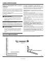
Fig. 1
GROUNDING
PIN
GROUND FAULT
OUTLET
POWER
CORD
DRIP
LOOP
Fig. 2
EXTENSION
CORD
If the saw is used with an extension cord, ensure the
connection of the tool’s power cord and the extension cord
are not on the ground.
If a protected outlet is not available, do not use the saw
until an outlet can be changed or auxiliary protection can
be obtained. These auxiliary protection devices are available
at your local retailer.
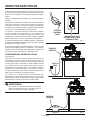
POSITION OF THE TILE SAW
See Figure 2.
To avoid the possibility of the tool plug or outlet getting
wet, position tile saw to one side of a wall-mounted outlet
to prevent water from dripping onto the outlet or plug. The
operator should arrange a “drip loop” in the cord connecting
the saw to the outlet. The “drip loop” is that part of the cord
below the level of the outlet, or the connector if an extension
cord is used, to prevent water traveling along the cord and
coming in contact with the outlet.
If the plug or outlet does get wet, DO NOT unplug the cord.
Disconnect the fuse or circuit breaker that supplies power
to the tool then unplug and examine for the presence of
water in the outlet.
WARNING:
To reduce the risk of electrocution, keep all
connections dry and off the ground. Do not touch
the plug with wet hands.

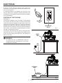
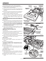
8 — English
FEATURES
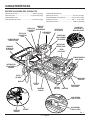
RUBBER
BOOT
WATER TRAY
EXTENSION
BEVEL LOCK
KNOB
ON/OFF
SWITCH
DEPTH STOP
LOCK KNOB
CUTTING WHEEL
GUARD
SLIDING TABLE
LOCK LEVER
DRAINAGE
DRAIN
CAP
SLIDING TABLE
FENCE
Fig. 3
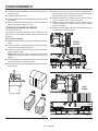
PRODUCT SPECIFICATIONS
Wheel Diameter ............................................................8 in.
Wheel Arbor .............................................................. 5/8 in.
Rip Capacity (Tile size) ...............................................24 in.
Diagonal Capacity (Tile size) ......................................18 in.
Maximum Depth of Cut .........................................2-3/4 in.
Rating ...........................................120 V~, 12 Amps, 60 Hz
No Load Speed .....................................5,000 r/min. (RPM)
CUTTING
WHEEL
MITER
GUIDE
MAX WATER
FILL LINE
WATER
TRAY
SLIDING
TABLE
FRAME
PULL
HANDLE
WHEELS
MIN WATER
FILL LINE
LASER
SWITCH
WHEEL
HOOD
WATER
FILTER
GREASE
PENCIL
STORAGE
MOTOR HEAD
LOCK KNOB
WRENCH
STORAGE

9 — English
FEATURES
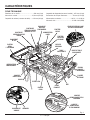
KNOW YOUR TILE SAW
See Figure 3.
The safe use of this product requires an understanding of
the information on the tool and in this operator’s manual as
well as a knowledge of the project you are attempting. Before
use of this product, familiarize yourself with all operating
features and safety rules.
8 in. TILE CUTTING WHEEL - An 8 in. tile cutting wheel is
included with your saw.
WARNING:
Do not use wheels rated less than the speed of
this tool. Failure to heed this warning could result
in personal injury.
BEVEL LOCK KNOB - The bevel lock knob securely locks
the saw head at any bevel angle between 0º and 45º. It is
recommended that you only make bevel cuts at 0˚, 22.5˚,
and 45˚ angles.
WARNING:
Making bevel cuts at angles other than 0˚, 22.5˚,
and 45˚ angles could cause the cutting wheel to
come in contact with the sliding table resulting in
damage to the unit and/or possible serious injury.
ADJUSTABLE LASER ALIGNMENT SYSTEM - For more
accurate cuts, a laser guide is included with the tile saw.
When used properly, the laser guide makes accurate,
precision cutting simple and easy. Simply push the button
to turn the laser on or off.
MITER GUIDE - The easy-to-read indicator on the miter
guide shows the exact angle for a miter cut with detents at
0°, 22.5°, and 45°.
ON/OFF SWITCH - This saw has an easy access power
switch located on the saw arm. To lock the switch, install
a padlock (not included) through the hole in the switch
trigger. When the lock is installed and locked, the switch is
inoperable. Store the padlock key in another location.
SLIDING TABLE - The sliding table allows the user to slide
the workpiece into the cutting wheel for accurate cuts.
SPLASH GUARD ASSEMBLY WITH TOOLESS
REMOVABLE SIDE GUARD - The splash guard helps
contain spray and mist.
SUBMERSIBLE PUMP - The submersible pump (not shown)
provides water to the cutting wheel.
WATER TRAY EXTENSION - When cutting larger tile, the
extension keeps work area cleaner and drier.
WRENCH STORAGE - The tile saw has a convenient storage
area specifically designed for wrenches.
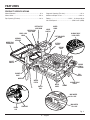
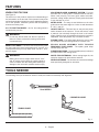
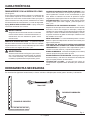
TOOLS NEEDED
The following tools (not included or drawn to scale) are needed for assembly and alignment:
Fig. 4
10 mm WRENCH
FRAMING SQUARE
COMBINATION SQUARE

10 — English
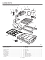
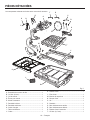
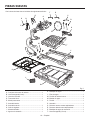
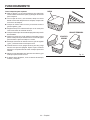
The following items are included with your tile saw:
MAX
MIN
LOOSE PARTS
A
R
B
T
D
M
H
G
L
I
P
K
J
Fig. 5
A - Motor head assembly ...............................................1
B - Hex key (6 mm) ......................................................... 1
C - Wheel wrench ...........................................................1
D - Arbor nut ...................................................................1
E - Cutting wheel ...........................................................1
F - Inner washer .............................................................1
G - Outer washer ............................................................1
H- Miter guide ...............................................................1
I - Sliding table .............................................................. 1
J - Frame .......................................................................1
K - Water tray .................................................................1
L - Water filter ................................................................1
M - Cap screw ................................................................4
N - Water pump ..............................................................1
O - Screw ........................................................................1
P - Washer ......................................................................1
Q - Rear splash guard ....................................................1
R - Side splash guard ..................................................... 1
S - Water tray extension ................................................. 1
T - Hex key (2.5 mm) ...................................................... 1
O
E
C
N
F
Q
S

11 — English
ASSEMBLY
Fig. 6
MOTOR HEAD
ASSEMBLY
WRENCH
STORAGE
HOLES
FRAME
SOCKET HEAD
SCREWS
POSTS
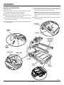
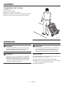
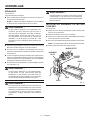
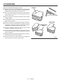
UNPACKING
See Figure 5.
This product requires assembly.
Carefully lift the parts from the carton and place on a level
work surface.
NOTE: Many of the Loose Parts are stored in the water
reservoir.
WARNING:
Do not use this product if any parts on the Loose
Parts list are already assembled to your product
when you unpack it. Parts on this list are not
assembled to the product by the manufacturer and
require customer installation. Use of a product that
may have been improperly assembled could result
in serious personal injury.
Inspect the tool carefully to make sure no breakage or
damage occurred during shipping.
Do not discard the packing material until you have carefully
inspected and satisfactorily operated the tool.
The saw is factory set for accurate cutting. After assembling
it, check for accuracy. If shipping has influenced the
settings, refer to specific procedures explained in this
manual.
If any parts are damaged or missing, please call
1-866-539-1710 for assistance.
WARNING:
If any parts are damaged or missing do not operate
this tool until the parts are replaced. Use of this
product with damaged or missing parts could
result in serious personal injury.
WARNING:
Do not attempt to modify this tool or create
accessories not recommended for use with this
tool. Any such alteration or modification is misuse
and could result in a hazardous condition leading
to possible serious personal injury.
WARNING:
Do not connect to power supply until assembly
is complete. Failure to comply could result in
accidental starting and possible serious personal
injury.
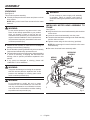
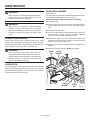
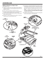
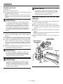
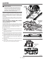
INSTALLING MOTOR HEAD ASSEMBLY TO
FRAME
See Figure 6.
Align the holes in the motor head assembly with the holes
on the frame.
Lower the motor head assembly onto the posts.
Thread socket head screws through motor head assembly
and into holes on frame.
Tighten screws using the 6 mm hex key (provided).
NOTE: Wrench storage is located in the back of the motor
head assembly.
Set motor head and frame assembly aside.

12 — English
MAX
MIN
ASSEMBLY
Fig. 7
WATER
FILTER
WATER TRAY
FILTER SLOTS
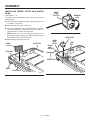
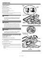
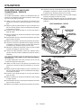
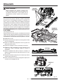
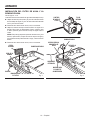
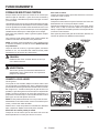
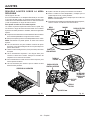
INSTALLING WATER FILTER AND WATER
PUMP
See Figures 7 - 9.
The water pump recirculates water from the tray to the
cutting wheel.
Locate filter slots and pump well in water tray. Pump well
is marked, “pump well.”
Slide filter into filter slots, as shown.
Locate the “Max/Min” water flow selector on the pump.
For best performance, start with the flow to “Max” to
control the flow of water over the wheel.
NOTE: Water flow can be adjusted during use by
removing the filter, reaching into water well and turning
flow selector on pump. Reinsert filter.
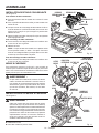
Place water pump into pump well.
WHEEL
PUMP WELL
POWER
CORD
NOTCH
Fig. 8
WATER
FLOW
SELECTOR
MAXIMUM
FLOW
WATER PUMP
POWER CORD
WATER
HOSE
NOTCH
PUMP
WELL

13 — English
WATER
TRAY
MOTOR HEAD
AND FRAME
ASSEMBLY
Fig. 9
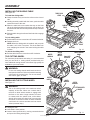
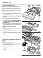
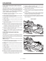
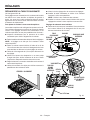
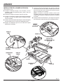
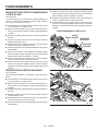
INSTALLING WATER TRAY
See Figure 8 - 9.
Place the water tray, with the pump and filter in place,
on a sturdy flat surface or on level ground.
Attach the water hose to the pump elbow.
Carefully lift the motor head and water tray frame
assembly over the water tray, as shown.
Tilt the water tray frame and insert heavy duty tab into
the bar slot on water tray.
Secure the water tray frame in place with latches on front
of the water tray.
LATCHES
HEAVY DUTY
TAB
BAR SLOT
BAR SLOT
RUBBER
BOOT
PUMP
POWER
CORD
Connect the pump power cord to the motor head power
cord. Check that the rubber boot is pulled over cord
connection to help keep water off the plug.
NOTE: The pump turns on when the motor is turned on.
Let the cutting wheel build up to full speed and wait for
the wheel to get wet before moving the material into the
wheel.
Rest power cord and water hose in the notches provided
on the water tray.
PUMP ELBOW
WATER HOSE
ASSEMBLY

14 — English
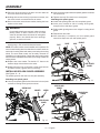
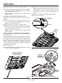
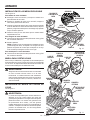
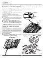
INSTALLING THE SLIDING TABLE
See Figure 10.
To install the sliding table:
Grasp the table firmly and set the rollers on the front of
rails.
Holding the table parallel with the frame, push the table
toward the back of the saw.
When the table lock lever reaches the stop on the front
rail on the right hand side of the frame, pull the lever out
and hold it out until the lock has passed the stop. Release
the lever.
Slide the table along the rails until the final rollers engage
the rails.
To lock sliding table:
Pull the table lock lever out and turn 90˚ counterclockwise.
Release the lever.
NOTE: When the sliding table is installed, and you push
the table, it will “click” into place. This is the table lock
lever snapping into a hole in the frame locking the table
in place.
To unlock the sliding table:
Pull the table lock lever out and turn 90˚ clockwise.
TILE CUTTING WHEEL
For maximum performance and safety, it is recommended
that you use the 8 in. cutting wheel provided with your
saw. Additional cutting wheels of the same high quality are
available at your local dealer.
WARNING:
Do not use cutting wheels rated less than the no
load speed of this tool. Failure to heed this warning
could result in personal injury. Do not use wheel
with cracks, gaps, or teeth.
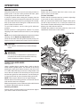
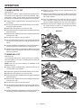
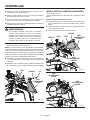
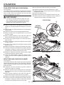
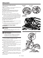
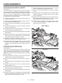
INSTALLING THE CUTTING WHEEL
See Figure 11.
WARNING:
A 8 in. tile cutting wheel is the maximum wheel
capacity of the saw. Never use a wheel that is
too thick to allow wheel washer to engage with
the flats on the arbor. Larger wheels will come
in contact with the splash hood, while thicker
wheels will prevent the wheel bolt from securing
the wheel on the arbor. Either of these situations
could result in a serious accident and can cause
serious personal injury.
Unplug the saw.
Lock table in front position.
Loosen wheel guard knob by turning counterclockwise
and open the cutting wheel guard.
ASSEMBLY
ARBOR
ARBOR
NUT
OUTER
WASHER
CUTTING
WHEEL
6 mm HEX
WRENCH
Fig. 11
WATER
NOZZLES
Fig. 10
SAW
FRONT
ROLLERS
SLIDING
TABLE
TABLE LOCK
LEVER
WHEEL
WRENCH
WHEEL GUARD
KNOB
INNER
WASHER
OUTER
WATER
NOZZLE
LOCK
UNLOCK
BYPASS
CUTTING WHEEL
GUARD

15 — English
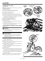
Fig. 12
Place the wheel wrench on the arbor nut then slide the
6 mm hex wrench into the arbor.
Holding the hex wrench firmly to prevent movement, turn
the wheel wrench counterclockwise to loosen.
Remove the arbor nut and outer washer, leaving the inner
washer on the arbor.
WARNING:
If inner washer has been removed, replace it before
placing wheel on arbor. Failure to do so could
cause an accident since the wheel will not tighten
properly. Never use wheels that have openings,
grooves, or teeth on this tool.
Place the cutting wheel onto arbor with the arrows on
wheel going in the counterclockwise direction.
NOTE: Two water nozzles come installed on this product. Be
sure to install cutting wheel so that there is a water nozzle on
each side of cutting wheel with water ports facing the cutting
wheel. The outer water nozzle can be easily removed for
installation of cutting wheel. Check that outer nozzle outlet
hole has been reattached with water port facing toward the
cutting wheel.
Replace the outer washer. The double “D” flats on the
washers align with the flats on the arbor.
Replace the arbor nut on the arbor. Using wheel wrench
and arbor wrench, tighten arbor nut securely.
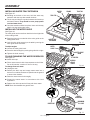
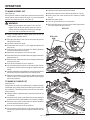
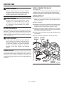
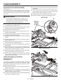
INSTALLING SPLASH GUARD ASSEMBLY
See Figures 12 - 14.
The splash guard on this saw is a two-part assembly.
Attaching rear splash guard:
Line up rear splash guard holes with screw hole and post
on back of cutting wheel guard, as shown.
ASSEMBLY
HOLE
SIDE SPLASH
GUARD
SCREW HOLE
POST
REAR SPLASH
GUARD
WASHER
POST
SIDE SPLASH
GUARD
Fig. 14
REAR SPLASH
GUARD
Fig. 13
RIDGE
GROOVE
REAR
SPLASH
GUARD
Insert screw through washer and splash guard then thread
into screw hole.
Tighten securely. Be careful not to overtighten.
Attaching side splash guard:
Install side splash guard over the rear splash guard.
Insert post, located on side of cutting wheel guard,
through hole in side flap of guard.
Settle splash guard grooves over ridges in cutting wheel
guard.
Repeat with other side.
After assembly is complete, pull rear splash guard
outward so flaps rest over side splash guard.
SCREW

16 — English
ASSEMBLY
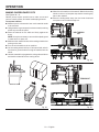
INSTALLING WATER TRAY EXTENSI
ON
See Figure 15.
Standing at the back of the saw, hold the water tray
extension with the tray tabs toward the slots.
Tilt the tray and slip the tray tabs between the frame top
and frame bottom. Tray should be over pump power
cord and water hose.
Once the extension slides into place, lower until the tray
tabs fit into the holes under frame.
INSTALLING THE MITER GUIDE
See Figure 16.
The miter guide can be used from both the left and right side
of the cutting wheel.
Place the slot on the underside of the miter guide on the
sliding table fence.
Lock the miter guide securely to the table by turning the
miter guide knob clockwise.
To adjust angles:
Loosen the miter guide knob.
Set to the desired angle by moving the guide left or right.
Tighten the knob securely.
FILLING/CHANGING THE WATER RESERVOIR
See Figure 17.
Install drain cap.
Fill the water reservoir with clean tap water to the fill line.
Do not fill past the “maximum” line on the tray.
To change reservoir water:
Unplug the saw.
Remove the drain cap and empty waste water into a
bucket. Do not allow the water to splash onto the ground
or around the machine.
Rinse the water reservoir thoroughly.
Discard the waste water in accordance with local
regulations.
Replace the drain cap and refill tray with clean water.
NOTE: Drain fits standard size garden hose.
Fig. 15
Fig. 16
WATER
TRAY
WATER TRAY
EXTENSION
TO TIGHTEN
MITER GUIDE
KNOB
MITER
GUIDE
TRAY TAB
TRAY TAB
TO LOOSEN
FRAME
DRAIN CAP
Fig. 17
MAXIMUM
FILL LINE
MINIMUM
FILL LINE
WATER
RESERVOIR
SLIDING
TABLE
FENCE

17 — English
ASSEMBLY
Fig. 18
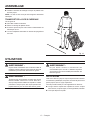
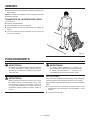
TRANSPORTING THE TILE SAW
See Figure 18.
Lock the sliding table.
Remove the water tray extension.
Be sure the hoses and cords do not drag on the ground.
Saw is easily moved, using pull handle and wheels.
OPERATION
WARNING:
Do not allow familiarity with tools to make you
careless. Remember that a careless fraction of a
second is sufficient to inflict serious injury.
WARNING:
Always wear eye protection with side shields
marked to comply with ANSI Z87.1 along with
hearing and breathing protection. Failure to do so
could result in objects being thrown into your eyes,
resulting in possible serious injury.
WARNING:
Do not use any attachments or accessories
not recommended by the manufacturer of this
tool. The use of attachments or accessories not
recommended can result in serious personal injury.
APPLICATIONS
This saw is designed to cut man-made tile, pavers, stone
tile, and pavers up to 4 in maximum.
You may use this tool for the purposes listed below:
Straight line cutting operations such as cross cutting,
mitering, ripping, plunging, and beveling
Cutting garden stone

18 — English
OPERATION
Fig. 19
SWITCH
ON
SWITCH
OFF
PADLOCK
ON/ OFF
SWITCH
Fig. 20
D-HANDLE
MOTOR HEAD
LOCK KNOB
MOTOR HEAD
ON/OFF SWITCH
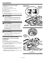
See Figure 19.
To turn your saw on:
Lift the switch to turn on.
To turn your saw off:
Press the switch down to turn off.
To lock your saw:
With the saw turned off, install a padlock (not included)
through the hole in the switch.
WARNING:
In the event of a power failure or when the tool is
not in use, turn the on/off switch off. This action
will prevent the tool from accidentally starting when
power returns.
WARNING:
ALWAYS make sure your workpiece is not in
contact with the cutting wheel before operating the
switch to start the tool. Failure to heed this warning
can cause the workpiece to be kicked back toward
the operator and result in serious personal injury.
WARNING:
To reduce the risk of accidental starting, ALWAYS
make sure the on/off switch is in the off position
before plugging tool into the power source.
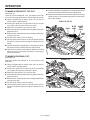
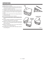
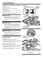
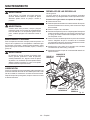
LOCKING/UNLOCKING THE MOTOR HEAD
FOR PLUNGE CUTS
See Figure 20.
To unlock and raise the motor head:
Firmly grasp the “D” handle and apply downward pressure
while at the same time turning the motor head lock knob
counterclockwise.
Slowly raise the motor head.
To lock the motor head:
Firmly grasp the “D” handle and apply downward pressure
while at the same time turning the motor head lock knob
clockwise to lock.
NOTE: For all through cuts, place the saw in the locked
position.

19 — English
OPERATION
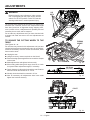
MAKING CUTS
Always draw the line to be cut on the tile using a marker or
grease pencil. If the tile is shiny and hard-to-mark, place
masking tape on the tile and mark the tape.
A common problem when cutting tile is straying from the
marked line. Once you’ve strayed from the mark, you can not
force the wheel back to the line by twisting the tile. Instead,
back up and recut the tile slicing off a small amount of tile
until the wheel is back on track.
To avoid this problem, use the miter guide whenever
possible.
Another problem is cutting difficult material. To prevent
chipping of the material at the end of the cut, use a plunge
cut.
NOTE: A more shallow blade adjustment may help minimize
chipping, see the Depth stop adjustments section.
Clean the saw table and miter guide frequently during use.
Debris from the cut material can interfere with tool function.
DANGER:
Laser radiation. Avoid direct eye contact with light
source.
WARNING:
Use of controls or adjustments or performance of
procedures other than those specified herein may
result in hazardous radiation exposure.
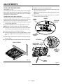
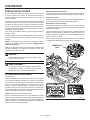
USING THE LASER GUIDE
See Figure 21.
Using a straight edge or square, draw a mark on the tile
with a marker or grease pencil. Turn the laser on and off by
pressing the laser guide switch located on the side of the
“D” handle. When the laser is turned on it will generate a red
line on the work surface. This line will let you see your mark
and the laser guide line at the same time, and will assist you
in lining up the mark for more accurate cutting of the tile.
NOTE: Laser may be difficult to see in bright sunlight.
With the wheel in the cutting position, move the tile until the
mark and the laser line are aligned.
Make several practice cuts on different styles and thickness
of material. Repeat the steps as necessary.
Removing Your Mark:
Position the tile so that the laser line is near the left edge of
your mark in order to remove the mark.
To Cut Your Mark:
Position the tile so that the laser line is near or over your
mark in order to cut the mark.
To Leave Your Mark:
Position the tile so that the laser line is near the right edge
of your mark in order to leave the mark.
After you have become familiar with using the laser guide,
you will be able to remove, cut, or leave your mark on the
work surface. Practice will teach you the correct position for
aligning your mark with the laser line.
To adjust the position of the laser guide line, refer to the
Adjustments section later in this manual.
Fig. 21
MARK
LASER SWITCH

20 — English
OPERATION
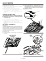
TO MAKE A CROSS CUT / RIP CUT
See Figure 22.
Cross/rip cuts are straight 90° cuts. The material is fed into
the cut at a 90° angle to the wheel, and the wheel is vertical.
Using a straight edge or square, draw a line on the tile
with a marker or grease pencil.
Set the miter guide to 0° for right side or 90° for left side
use. Tighten the lock knob, and lock in place.
Make sure miter guide is not in the cut path.
Place the material on the table and firmly against the miter
guide and fence.
Make sure the material is clear of the cutting wheel before
turning on the saw.
Flip the on/off switch to the on position.
Let the cutting wheel build up to full speed and wait for
the wheel to get wet before moving the material into the
wheel.
Hold the material firmly against the miter guide and fence
and slowly feed the material into the cutting wheel.
When the cut is made, turn the saw off. Wait for the cutting
wheel to come to a complete stop before removing any
part of the material.
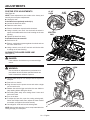
TO MAKE A DIAGONAL CUT
See Figure 23.
Diagonal cuts are also referred to as “long point-to-long
point cuts”.
Using a straight edge or square, draw a line on the tile
with a marker or grease pencil.
Set the miter guide to 0° for right side or 90° for left side
use. Tighten the lock knob, and lock in place.
Make sure miter guide is not in the cut path.
Place the material on the table and firmly against the miter
guide and fence.
Make sure the material is clear of the cutting wheel before
turning on the saw.
Flip the on/off switch to the on position.
Let the cutting wheel build up to full speed and wait for
the wheel to get wet before moving the material into the
wheel.
DIAGONAL CUT
Fig. 23
SLIDING
TABLE
FENCE
CROSS CUT / RIP CUT
MARK
MITER
GUIDE
Fig. 22
LOCK
KNOB
Hold the material firmly against the miter guide and fence
and slowly feed the material into the cutting wheel.
When the cut is made, turn the saw off. Wait for the cutting
wheel to come to a complete stop before removing any
part of the material.
La page est en cours de chargement...
La page est en cours de chargement...
La page est en cours de chargement...
La page est en cours de chargement...
La page est en cours de chargement...
La page est en cours de chargement...
La page est en cours de chargement...
La page est en cours de chargement...
La page est en cours de chargement...
La page est en cours de chargement...
La page est en cours de chargement...
La page est en cours de chargement...
La page est en cours de chargement...
La page est en cours de chargement...
La page est en cours de chargement...
La page est en cours de chargement...
La page est en cours de chargement...
La page est en cours de chargement...
La page est en cours de chargement...
La page est en cours de chargement...
La page est en cours de chargement...
La page est en cours de chargement...
La page est en cours de chargement...
La page est en cours de chargement...
La page est en cours de chargement...
La page est en cours de chargement...
La page est en cours de chargement...
La page est en cours de chargement...
La page est en cours de chargement...
La page est en cours de chargement...
La page est en cours de chargement...
La page est en cours de chargement...
La page est en cours de chargement...
La page est en cours de chargement...
La page est en cours de chargement...
La page est en cours de chargement...
La page est en cours de chargement...
La page est en cours de chargement...
La page est en cours de chargement...
La page est en cours de chargement...
La page est en cours de chargement...
La page est en cours de chargement...
La page est en cours de chargement...
La page est en cours de chargement...
La page est en cours de chargement...
La page est en cours de chargement...
La page est en cours de chargement...
La page est en cours de chargement...
La page est en cours de chargement...
La page est en cours de chargement...
La page est en cours de chargement...
La page est en cours de chargement...
La page est en cours de chargement...
La page est en cours de chargement...
La page est en cours de chargement...
La page est en cours de chargement...
La page est en cours de chargement...
La page est en cours de chargement...
La page est en cours de chargement...
La page est en cours de chargement...
La page est en cours de chargement...
La page est en cours de chargement...
La page est en cours de chargement...
La page est en cours de chargement...
La page est en cours de chargement...
La page est en cours de chargement...
La page est en cours de chargement...
La page est en cours de chargement...
La page est en cours de chargement...
La page est en cours de chargement...
La page est en cours de chargement...
La page est en cours de chargement...
-
 1
1
-
 2
2
-
 3
3
-
 4
4
-
 5
5
-
 6
6
-
 7
7
-
 8
8
-
 9
9
-
 10
10
-
 11
11
-
 12
12
-
 13
13
-
 14
14
-
 15
15
-
 16
16
-
 17
17
-
 18
18
-
 19
19
-
 20
20
-
 21
21
-
 22
22
-
 23
23
-
 24
24
-
 25
25
-
 26
26
-
 27
27
-
 28
28
-
 29
29
-
 30
30
-
 31
31
-
 32
32
-
 33
33
-
 34
34
-
 35
35
-
 36
36
-
 37
37
-
 38
38
-
 39
39
-
 40
40
-
 41
41
-
 42
42
-
 43
43
-
 44
44
-
 45
45
-
 46
46
-
 47
47
-
 48
48
-
 49
49
-
 50
50
-
 51
51
-
 52
52
-
 53
53
-
 54
54
-
 55
55
-
 56
56
-
 57
57
-
 58
58
-
 59
59
-
 60
60
-
 61
61
-
 62
62
-
 63
63
-
 64
64
-
 65
65
-
 66
66
-
 67
67
-
 68
68
-
 69
69
-
 70
70
-
 71
71
-
 72
72
-
 73
73
-
 74
74
-
 75
75
-
 76
76
-
 77
77
-
 78
78
-
 79
79
-
 80
80
-
 81
81
-
 82
82
-
 83
83
-
 84
84
-
 85
85
-
 86
86
-
 87
87
-
 88
88
-
 89
89
-
 90
90
-
 91
91
-
 92
92


RIDGID R4040S-FT3500-FT3508-FT7007-FT7001 Manuel utilisateur
- Catégorie
- Outils électroportatifs
- Taper
- Manuel utilisateur
- Ce manuel convient également à
dans d''autres langues
Documents connexes
Autres documents
-
Delta 96-110 Le manuel du propriétaire
-
-
Ryobi WS722-FT8018 Manuel utilisateur
-
Ryobi Saw WS750L Manuel utilisateur
-
-
-
-
-
Ryobi WS721S Manuel utilisateur
-