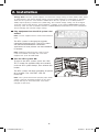
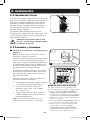
Tripp Lite SmartOnline Le manuel du propriétaire
- Catégorie
- Alimentations sans interruption (UPS)
- Taper
- Le manuel du propriétaire
Ce manuel convient également à

1
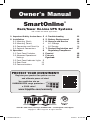
Owner’s Manual
SmartOnline
®
Rack/Tower On-Line UPS Systems
Not suitable for mobile applications.
1. Important Safety Instructions 2
2. Installation 3
2.1 Mounting (Rack) 3
2.2 Mounting (Tower) 4
2.3 Connection and Start-Up 4
2.4 Optional Connections 5
3. Operation 8
3.1 Front Panel Switches 8
3.2 Advanced Operational 8
Settings
3.3 Front Panel Indicator Lights 9
3.4 Rear Panel 11
3.5 Communications 12
4. Troubleshooting 13
5. Battery Replacement 14
6. Storage and Service 16
6.1 Storage 16
6.2 Service 16
7. Product Registration and 17
Regulatory Compliance
Español 18
Français 35
Русский
52
1111 W. 35th Street, Chicago, IL 60609 USA • www.tripplite.com/support
Copyright © 2017 Tripp Lite. All rights reserved.
PROTECT YOUR INVESTMENT!
Register your product for quicker service
and ultimate peace of mind.
You could also win an
ISOBAR6ULTRA surge protector—
a $100 value!
www.tripplite.com/warranty
17-06-040-932882.indb 1 6/29/2017 10:33:09 AM

2
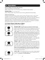
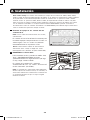
1. Important Safety Instructions
UPS Location Warnings
• Install the UPS system indoors, away from excess moisture or heat, conductive
contaminants, dust or direct sunlight.
• For best performance, keep the indoor temperature between 32º F and 104º F
(0º C and 40º C).
• Leave adequate space around all sides of the UPS system for proper ventilation.
• Do not mount the UPS system with its front or rear panel facing down (at any angle).
Mounting in this manner will seriously inhibit the UPS system’s internal cooling,
eventually causing product damage not covered under warranty.
UPS Connection Warnings
• Connect the UPS system directly to a properly grounded AC power outlet. The outlet
must be installed near the UPS system and must be easily accessible for disconnection.
• To reduce the risk of fire, connect only to a circuit provided with 20 amperes maximum
branch circuit overcurrent protection in accordance with your local and National
Electrical Code (NEC), ANSI/NFPA 70.
• Do not modify the UPS system’s plug, and do not use an adapter that would eliminate
the UPS system’s ground connection. Do not plug the UPS system into itself; this will
damage the UPS system.
• Do not use extension cords to connect the UPS system to an AC outlet.
• If the UPS system receives power from a motor-powered AC generator, the generator
must provide clean, filtered, computer-grade output.
Equipment Connection Warnings
• Use of this equipment in life support applications where failure of this equipment can
reasonably be expected to cause the failure of the life support equipment or to
significantly affect its safety or effectiveness is not recommended.
• Do not connect surge suppressors or extension cords to the output of the UPS system.
This might damage the UPS system and may affect the surge protector and UPS system
warranties. Connecting a Tripp Lite power distribution unit (PDU) to the output of the
UPS system is safe and will not void the warranty.
Battery Warnings
• Refer to Section 5: Battery Replacement for a complete list of battery warnings.
SAVE THESE INSTRUCTIONS
This manual contains instructions and warnings that should be followed during
the installation, operation and storage of this product. Failure to heed these
warnings may affect the warranty.
17-06-040-932882.indb 2 6/29/2017 10:33:15 AM

3
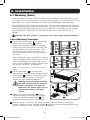
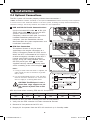
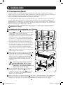
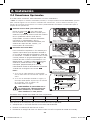
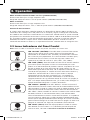
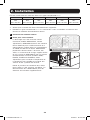
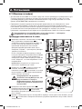
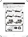
2. Installation
1
2
3
D
D
E
E
4
F
F
C
B
C
B
A
B
B
A
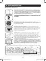
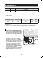
2.1 Mounting (Rack)
• Use the included rackmount shelves and mounting hardware to mount the UPS system
in a 4-post rack or rack enclosure. To mount the UPS system in a 2-post (telecom) rack,
order Tripp Lite’s 2-Post Rackmount Kit (model 2POSTRMKITWM, sold separately).
• The instructions in this manual are for common rack and rack enclosure types and may
not be appropriate for all mounting applications. The user must determine the fitness of
hardware and procedures before mounting. If hardware or procedures are not suitable
for the application, contact the manufacturer of the rack or rack enclosure for a
solution.
Warning: The UPS system is very heavy—be careful when moving or lifting it.
4-Post Mounting Procedure
1
The included plastic pegs
A
will support the
empty rackmount shelves
B
until the
permanent mounting hardware is installed.
Insert a peg near the center of the front and
rear bracket of each shelf as shown. (Each
front bracket has six holes and each rear
bracket has three holes.) The pegs will snap
into place.
After installing the pegs, expand each shelf to
match the depth of the vertical rack rails. The
pegs will fit through the square holes in the
rack rails to support the shelves. Confirm that
the shelves are level in all directions.
Note: The support ledge of each shelf must face
inward.
2
Secure the shelves
B
to the rack rails
permanently using the longer included screws
and washers
C
as shown. (Place four screws
at the front and four screws at the back.)
Tighten all screws before proceeding.
Warning: Do not attempt to install
the UPS system until the required
screws have been inserted and
tightened. The plastic pegs will not
support the weight of the UPS
system.
3
Attach the mounting brackets
D
to the
forward mounting holes of the UPS system
using the shorter included screws
E
. The
mounting bracket ears must face forward.
4
With the aid of an assistant, lift the UPS system and slide it onto the mounting
shelves. Insert four of the included screws
F
through the mounting bracket ears and
into the vertical rack rails. Tighten all screws securely.
17-06-040-932882.indb 3 6/29/2017 10:33:19 AM

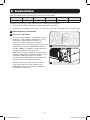
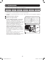
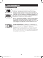
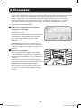
4
1
2
Some models may differ.
1
Voltage Selection Mode
Please follow below procedure to select the
output voltage by front panel.
1. Press the ON/TEST and OFF buttons
simultaneously to enter “Voltage Selection”
mode. The three LEDs labeled VOLTAGE
SELECTION MODE will flash when you have
entered this mode.
2. Press the ON/TEST button to select the
output voltage from 200 to 240.
3. After selecting the desired output voltage,
press the ON/TEST and OFF buttons
simultaneously to save your selection and
exit “Voltage Selection” mode.
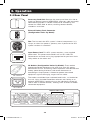
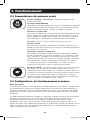
2. Installation
2.2 Mounting (Tower)
The UPS system can be mounted in an upright
tower position when used with Tripp Lite’s
optional base stand kit (model 2-9USTAND, sold
separately). When mounting the UPS system in a
tower position, make sure the control panel is
closer to the top of the cabinet than the bottom.
The control panel can be rotated to match the
orientation of the UPS system. Pull the panel
out, rotate it and push it back into place as
shown.
Warning: The UPS system is very
heavy—be careful when moving or
lifting it.
2.3 Connection and Start-Up
1
Plug the UPS system into an electrical
outlet.
Note: The UPS system does not include an input
power cord.
Connect a user-supplied power cord to the
IEC-320-C20 input receptacle. The power
cord should have an IEC-320-C19 connector
on one end and a plug appropriate for your
local site’s utility outlet on the other end.
The UPS system must be connected to a
dedicated circuit of sufficient amperage.
Refer to the UPS system nameplate for input
requirements.
After the UPS system is plugged in, the
following sequence of events will occur:
1. The fan will turn on and all LEDs will
illuminate momentarily.
2. The percent level LEDs (25%, 50%, 75%
and 100%) will illuminate one at a time.
3. The “LINE” and “LOAD” LEDs will
illuminate to indicate normal operation.
Note: Power will not be supplied to the outlets until
the UPS system is turned on.
17-06-040-932882.indb 4 6/29/2017 10:33:21 AM

5
Voltage Note: The UPS system supports a nominal AC voltage setting of 200V, 208V, 220V, 230V
or 240V. 230V is the factory default setting. The full output capacity of 2,500 watts is available
when the UPS system is set at 230V or 240V. When the UPS system is set at 200V, 208V or
220V, output capacity is reduced to 2,400 watts. The nominal voltage setting can be changed
using the control panel buttons, with PowerAlert
®
software or the optional WEBCARDLX internal
accessory card. See the PowerAlert software or WEBCARDLX documentation for more information
about changing the nominal voltage setting.
2
3
Some models may differ.
2. Installation
2
Plug equipment into the UPS system’s AC
outlets.
Note: Use the supplied C13 to C14 interconnection
cord.
The UPS system is designed to support
computer equipment only. The UPS system
will become overloaded if household
appliances or laser printers are connected to
its outlets.
Note: Additional interconnection cords (C13 to
C14) are available from Tripp Lite. Visit www.
tripplite.com. (Part # P004-006)
3
Turn the UPS system ON.
To turn on the UPS system, press the “ON/
TEST” button for approximately one second
until the UPS system beeps, then release the
button.
The UPS system will begin providing AC power
to its outlets. The “ON LINE” LED will
illuminate.
Note: UPS system will function properly upon initial
startup, however, maximum runtime for the unit’s
battery will only be accessible after it has been
charged for 24 hours.
17-06-040-932882.indb 5 6/29/2017 10:33:22 AM

6
4-5
2a
Some models may differ.
2b
1
USB and RS-232 Serial Communications
Use the included USB cable
1a
or RS-232
(DB9) serial cable
1b
to connect the UPS
system’s communication port to a
computer’s communication port. Install the
included PowerAlert software on the
computer. (See the PowerAlert software
documentation for system requirements and
installation instructions.)
2
EPO Port Connection
This optional feature is only for those
applications that require connection to a
facility’s Emergency Power Off (EPO) circuit.
When the UPS is connected to this circuit, it
enables emergency shutdown of the UPS’s
inverter and inhibits transfer to internal
bypass. Using the cable provided, connect
the EPO port of your UPS
2a
to a user-
supplied normally closed or normally open
switch according to the circuit diagram
2b
.
Notes:
1. If using a cable other than what is supplied, the
cable should not have a resistance of greater
than 5 ohms.
2. If a non-latching EPO switch is used, the EPO
must be held for a minimum of 1 second. This
does not apply to a latching EPO switch.
CAUTION: The EPO port is not a
phone line surge suppressor; do
not connect a phone line to this
port.
1b
Some models may differ.
1a
Some models may differ.
2. Installation
2.4 Optional Connections
The UPS system will function properly without these connections.*
* Note: PowerAlert software (included) or the optional WEBCARDLX internal accessory card is required
to control some of the advanced features of the UPS system, including economy mode and frequency
conversion settings. The factory defaults are suitable for most applications.
UPS Unit State when asserting EPO with AC line present:
LEDs Output Fans Serial SNMP USB
OFF OFF ON ON ON ON
To restart the UPS unit after asserting EPO with AC line present:
1. Verify that the EPO assertion has been removed or cleared.
2. Remove AC line power to the UPS unit.
3. Reapply AC line power. Now the UPS will start back up in Standby mode.
17-06-040-932882.indb 6 6/29/2017 10:33:24 AM

7
3
4
Some models may differ.
Some models may differ.
UPS Unit State when asserting EPO without AC line power:
LEDs Output Fans Serial SNMP USB
OFF OFF OFF OFF OFF OFF
To restart the UPS unit after asserting EPO without AC line power:
1. Verify that the EPO assertion has been removed or cleared.
2. Reapply AC line power to the UPS unit. Now the UPS will start back up in Standby mode.
3
External Battery Connection
4
Accessory Card Slot
The slot accommodates an optional internal
accessory card (model: WEBCARDLX, sold
separately). WEBCARDLX provides an
Ethernet network interface for remote
monitoring and control of the UPS system via
SNMP, Web or telnet. WEBCARDLX enables
remote reboots, shutdowns, load monitoring,
condition reporting and more. Use
WEBCARDLX with an optional environmental
sensor (model E2MT, E2MTDI, E2MTDO and
E2MTHDI, sold separately) to monitor
temperature and humidity or to control and
monitor alarms and security systems.
Remove the cover panel from the slot to
insert the accessory card. Refer to the
WEBCARDLX documentation for additional
installation instructions.
2. Installation
17-06-040-932882.indb 7 6/29/2017 10:33:26 AM

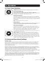
8
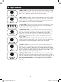
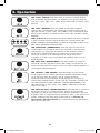
3. Operation
3.1 Front Panel Switches
“ON/TEST” Button: This button controls four separate functions:
UPS System Power ON
To turn on the UPS system, press the “ON/TEST” button for
approximately one second until the UPS system beeps, then release
the button. The “ON LINE” LED will illuminate.
UPS System Self-Test
To initiate a self-test of the battery during normal on-line operation,
press this button for approximately one second until the UPS system
beeps, then release it. The UPS system will shift to battery power for
10 seconds.
Note: All LEDs illuminate during a self-test.
Alarm Silence
To silence the UPS system’s on battery alarm, press this button and
hold it until the UPS system beeps, then release the button.
UPS System Cold Start
To use the UPS system as a stand-alone power source when AC
power is unavailable (i.e. during a blackout), press this button and
hold it until the UPS system beeps, then release the button. The
UPS system will then provide battery power to its outlets.*
* The “ON BATT” indicator light will be illuminated since the UPS system will
be operating from battery power.
“OFF” Button: This button turns off power to the UPS system’s
outlets. Press this button and hold it until the UPS system beeps,
then release it. The battery will continue to charge and the fan will
continue to operate even when the outlets are off. To turn the UPS
system off completely, including the battery charger, unplug the UPS
system’s power cord after pressing the “OFF” switch.
3.2 Advanced Operational Settings
Economy Mode
The UPS system supports economy mode operation to reduce energy consumption and
BTU emissions. In economy mode, the UPS system operates with increased efficiency
when the quality of utility power is satisfactory to pass through to connected equipment
without double conversion.
Economy mode saves energy by suspending double conversion when incoming voltage is
within -12%/+10% of the nominal voltage setting. If the nominal voltage setting is 230V,
the UPS system will remain in economy mode while utility line voltage is between
approximately 202V and 253V. If utility line voltage falls outside this range, the UPS
system will either switch back to standard on-line, double conversion mode or it will switch
to battery backup mode, depending on the severity of the voltage deviation.
Economy mode can be enabled (or disabled) through the included PowerAlert software or
the optional WEBCARDLX internal accessory card. The UPS system's yellow “BYPASS” LED
will illuminate continuously when economy mode is enabled. Refer to the PowerAlert or
WEBCARDLX documentation for more information.
17-06-040-932882.indb 8 6/29/2017 10:33:26 AM

9
On-line, double-conversion mode (default)
Typical line efficiency at full load: 89%
Output voltage range: ± 2% of nominal setting (200/208/220/230/240V)
Economy mode
Typical line efficiency at full load: 97%
Output voltage range: -12%/+10% of nominal setting (200/208/220/230/240V)
Frequency Conversion
The UPS system automatically selects 50 Hz or 60 Hz operation based on utility power
conditions at start-up and regulates output power within ± 0.05 Hz of the selected
frequency. The UPS system also has an advanced setting that allows continuous frequency
conversion from 50 Hz to 60 Hz or from 60 Hz to 50 Hz. The advanced frequency
conversion setting is accessible through the included PowerAlert software or the optional
WEBCARDLX internal accessory card. When continuous frequency conversion is enabled,
the maximum output capacity of the UPS system is derated by 25%.
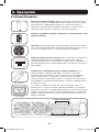
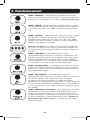
3.3 Front Panel Indicator Lights
Note: All LEDs illuminate during a UPS system self-test.
3. Operation
“ON LINE” LED: This green LED will illuminate continuously to
indicate the UPS system is operating normally in on-line mode
(filtering and resynthesizing AC line input to provide pure sine wave
output). When this LED is illuminated, the load level of the UPS
system is displayed on the % level LEDs (25%, 50%, 75%, 100%).
“LINE” LED: This green LED will illuminate continuously to indicate
the utility-supplied AC line voltage at the wall outlet is nominal. It
will flash if the line voltage is outside the nominal range (either too
low or too high). User action is not required when the LED flashes;
the UPS system continuously and automatically filters AC line
power to provide equipment with pure sine wave AC power,
regardless of brownout or overvoltage conditions. If this LED is off,
then AC line voltage is not present (blackout) or is at an extremely
high voltage, and the UPS system will provide connected
equipment with power from its battery system.
“BYPASS” LED: This yellow LED will illuminate continuously when
the UPS system is in economy mode. The LED will flash when the
UPS system is bypass mode, indicating that the UPS system’s DC/
AC inverter is deactivated. The red “FAULT” LED will also illuminate
if the UPS system is in bypass mode. During normal operation the
bypass LED will illuminate briefly when the unit is plugged in. If an
internal fault or overload occurs, the LED will flash repeatedly to
show that connected equipment will receive filtered AC line power,
but will not receive battery power during a blackout. In this case,
contact Tripp Lite for service.
“FAULT” LED: This red LED will flash when the UPS system detects
an internal fault. If the condition persists after restarting the UPS
system, see Section 4: Troubleshooting.
17-06-040-932882.indb 9 6/29/2017 10:33:27 AM

10
3. Operation
“LOAD” LED: This green LED will illuminate when the UPS system
is receiving AC power. It also indicates that the % level LEDs (25%,
50%, 75%, 100%) are displaying the UPS load level.
“BATT” LED: This green LED will illuminate when the UPS system
is operating from battery power. It indicates that the % level LEDs
(25%, 50%, 75%, 100%) are displaying the battery charge level.
(The “ON BATT” LED will also be illuminated.)
% Level LEDs: These dual-function LEDs will indicate the % level
for either the load level (if the “LOAD” LED is lit) or the battery
charge level (if the “BATT” LED is lit).
“OVERLOAD” LED: This red LED will illuminate continuously to
indicate that the UPS system’s capacity has been exceeded. The
UPS alarm will beep continuously. Immediately unplug some
equipment until the LED and alarm go off. If the overload is not
corrected immediately, the UPS system will go from on-line to
bypass mode.
“BATT LOW” LED: This yellow LED will illuminate when the UPS
system’s battery charge level is low. The UPS alarm will beep until
the batteries are either depleted or adequately recharged.
“ON BATT” LED: This green LED will illuminate continuously to
indicate that AC line voltage is absent (or out of range) and the
UPS system is providing equipment with battery-derived AC power.
The UPS system will also beep every two seconds (unless silenced
by the “ON/TEST” button) and the % level LEDs (25%, 50%, 75%,
100%) will display the battery charge level.
“REPLACE BATT” LED: This red LED will illuminate continuously
and the UPS alarm will beep every two seconds if the UPS system
fails the automatic self-test. Allow the UPS system to charge for at
least 12 hours and perform a self-test as described in Section
3.1: Front Panel Switches. If the condition persists, contact
Tripp Lite.
17-06-040-932882.indb 10 6/29/2017 10:33:29 AM

11
IEC-320-C20
CONTROLLABLE LOAD 1
CONTROLLABLE LOAD 2 UNSWITCHED
IEC-320-C13
IEC-320-C19
3. Operation
3.4 Rear Panel
Accessory Card Slot: Remove the cover panel from this slot to
install an optional internal WEBCARDLX accessory, sold separately.
WEBCARDLX provides a network interface for monitoring and
control via SNMP, Web or telnet, enabling remote reboots,
shutdowns and more.
External Battery Pack Connector
(Configuration Varies By Model)
Fan: The fan cools the UPS system’s internal components. It is
always on when line power is present, even if power to the UPS
system’s outlets is turned off.
Input Power Cord: This UPS system requires a user-supplied
power cord. This power cord should have an IEC-320-C19
connector on one end and a plug appropriate for your local site's
utility outlet on the other end.
AC Outlets (Configuration Varies By Model): These outlets
provide connected equipment with pure sine wave AC output
derived from the AC line during normal operation and derived from
battery power during blackouts and severe brownouts or
overvoltages. Output power is filtered to protect connected
equipment against damaging surges and line noise.
The outlets are divided into numbered load banks, as labelled on
the unit. Using included PowerAlert software and cabling or an
optional WEBCARDLX, load banks may be individually turned off
and on from a remote location, allowing users to reset or reboot
connected equipment.
17-06-040-932882.indb 11 6/29/2017 10:33:32 AM

12
RS-232 (DB9)
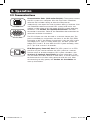
3.5 Communications
Communication Ports (USB and/or RS-232): These ports connect
the UPS system to a computer. Use with Tripp Lite’s PowerAlert
software and included cabling to allow the computer to
automatically save open files and shut down during a blackout. Also
use PowerAlert software to control UPS system load banks and
monitor a wide variety of AC line power and UPS system operating
conditions. See Section 2.4: Optional Connections for cable
connection instructions. Refer to the PowerAlert documentation for
software installation instructions.
The RS-232 port can also be used as a contact closure port. The
port’s numbered pin assignments are shown in the RS-232 (DB9)
illustration at left. If the battery charge level is low, the UPS system
will bridge pins 1 and 5. If utility power fails, the UPS system will
bridge pins 8 and 5. To shut down the UPS system remotely, short
pin 3~pin 9 for at least 3.8 seconds.
EPO (Emergency Power Off) Port: The UPS system has an EPO
port that may be used to connect the UPS system to a contact
closure switch to enable emergency UPS system shutdown. See
Section 2.4: Optional Connections for more information. If the
unit has been shut down due to an EPO event, it will be necessary
to disconnect the unit from utility power to reset the unit. After
re-connecting to utility power, see Section 2.3 Installation for
start-up instructions.
USB
3. Operation
17-06-040-932882.indb 12 6/29/2017 10:33:33 AM

13
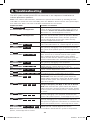
The UPS system control panel LEDs will illuminate in the sequences listed below to
indicate operational problems.
Note: If the “FAULT” LED illuminates, determine the specific fault condition by activating the error
code LEDs. To activate the error code LEDs, press the “ON/TEST” button until the UPS system beeps,
then release the button. The error code LEDs will illuminate for five seconds.
Illuminated LEDs Condition and Solution
On: REPLACE BATT
Error Code LEDs: Not Applicable
Replace Battery: Allow the UPS system to charge for
at least 12 hours and perform a UPS system self-test as
described in Section 3.1: Front Panel Switches. If the
LED remains on, contact Tripp Lite for service.
Flashing: LINE
Error Code LEDs: Not Applicable
Input Abnormal: Utility power voltage or frequency is too
high or too low for the UPS system to operate in BYPASS
mode. If an inverter failure occurs, the UPS system will
not pass through utility power to the outlets and any
connected equipment will turn off.
On: FAULT
Error Code LEDs: 50% 100%
Battery Weak: Allow the UPS system to charge for 12
hours. If the LED remains on, contact Tripp Lite for service.
On: FAULT
Error Code LEDs: 25% 75%
Inverter Over-Current: Reduce the load supported by the
UPS system by unplugging some equipment. Restart the
UPS system. If the problem persists, contact Tripp Lite for
service.
On: FAULT
Error Code LEDs: 25% 75% 100%
Internal Temperature Too High: Confirm that adequate
space exists for air to circulate near the UPS system’s
vents. Confirm that the UPS system’s fan is working
properly. Confirm that the ambient temperature does not
exceed recommended levels. Restart the UPS system.
On: FAULT
Error Code LEDs: 25% 50%
Inverter Overload: Reduce the load supported by the
UPS system by unplugging some equipment.
On: FAULT
Error Code LEDs: 25% 50% 100%
Charger Out of Order: Restart the UPS system. If the
problem persists, contact Tripp Lite for service.
On: FAULT
Error Code LEDs: 25% 50% 75%
Fan Out of Order: Restart the UPS system. If the problem
persists, contact Tripp Lite for service.
On: FAULT
Error Code LEDs: 25% 50% 75% 100%
Bypass Phase Can’t Lock: Restart the UPS system. If
the problem persists, contact Tripp Lite for service.
On: FAULT
Error Code LEDs: BATT 25%
Utility Voltage Low and Battery Disconnected at
Initialization: Shut down the UPS system. Check the
internal battery connections. Correct the AC input voltage.
Restart the UPS system. If the problem persists, contact
Tripp Lite for service.
On: FAULT
Error Code LEDs: BATT 25% 100%
Battery Disconnected at Initialization and Utility
Voltage or Frequency Too High or Too Low in On-Line
Mode: Shut down the UPS system. Check the internal
battery connections. Correct the AC input voltage. Restart
the UPS system. If the problem persists, contact Tripp Lite
for service.
On: FAULT
Error Code LEDs: BATT 25% 75%
Input Over-Current: Reduce the load supported by the UPS
system by unplugging some equipment. Restart the UPS
system. If the problem persists, contact Tripp Lite for service.
On: FAULT
Error Code LEDs: BATT 25% 50%
Bypass Overload: Reduce the load supported by the UPS
system by unplugging some equipment. Either wait for the
UPS system to recognize the load reduction or restart the UPS
system. If the problem persists, contact Tripp Lite for service.
On: FAULT
Error Code LEDs: BATT 25% 50% 100%
Battery Voltage Too High: Restart the UPS system. If the
problem persists, contact Tripp Lite for service.
Note: All other error codes indicate internal fault conditions. Restart the UPS system. If the problem
persists, contact Tripp Lite for service.
4. Troubleshooting
17-06-040-932882.indb 13 6/29/2017 10:33:33 AM

14
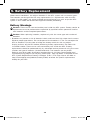
Under normal conditions, the original batteries in the UPS system will last several years.
The batteries are designed for hot-swap replacement (i.e. replacement while the UPS
system is in ON mode), but some qualified service personnel may wish to put the UPS
system in OFF mode and disconnect equipment before proceeding.
Battery Warnings
Caution: There are no user-serviceable parts inside the UPS system. Battery service or
replacement must be performed or supervised by qualified service personnel familiar
with batteries and the required precautions.
Caution: When replacing batteries, replace only with the same type and number of
batteries.
• Batteries can present a risk of electrical shock and burn from high short-circuit current.
Observe proper precautions. Do not dispose of the batteries in a fire. Do not open the
UPS or batteries. Do not short or bridge the battery terminals with any object.
Unplug and turn off the UPS before performing battery replacement. Use tools with
insulated handles. There are no user-serviceable parts inside the UPS. Battery
replacement should be performed only by authorized service personnel using the same
number and type of batteries (Sealed Lead-Acid). The batteries are recyclable.
Refer to your local codes for disposal requirements or visit http://www.tripplite.com/
support/recycling-program for recycling information. Tripp Lite offers a complete line of
UPS System Replacement Battery Cartridges (R.B.C.).Visit Tripp Lite on the Web at
http://www.tripplite.com/products/battery-finder/ to locate the specific replacement
battery for your UPS.
5. Battery Replacement
17-06-040-932882.indb 14 6/29/2017 10:33:33 AM

15
1
2
3
6
5
4
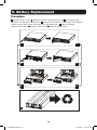
Procedure
1
Remove Front Panel
2
Remove Battery Compartment Cover
3
Disconnect Old
Batteries and Remove Old Batteries
4
Insert New Batteries and Connect New Batteries
(Attach battery connectors black-to-black and red-to-red.)
5
Replace Battery
Compartment Cover
6
Replace Front Panel
7
Recycle Old Batteries
7
5. Battery Replacement
17-06-040-932882.indb 15 6/29/2017 10:33:40 AM

16
6. Storage and Service
6.1 Storage
First turn the UPS system OFF: press the “OFF” switch to turn power off at the UPS
system’s outlets, then disconnect the UPS system’s power cord from the wall outlet. Next,
disconnect all equipment to avoid battery drain. If the UPS system will be stored for an
extended period of time, recharge the UPS system’s batteries fully every three months by
plugging the UPS system into a live AC outlet and allowing the UPS system to charge for
4-6 hours. If the UPS system’s batteries are left discharged for an extended period of time,
they may suffer a permanent loss of capacity.
6.2 Service
A variety of Extended Warranty and On-Site Service Programs are also available from
Tripp Lite. For more information on service, visit www.tripplite.com/support. Before returning
your product for service, follow these steps:
1. Review the installation and operation procedures in this manual to insure that the
service problem does not originate from a misreading of the instructions.
2. If the problem continues, do not contact or return the product to the dealer. Instead,
visit www.tripplite.com/support.
3. If the problem requires service, visit www.tripplite.com/support and click the Product
Returns link. From here you can request a Returned Material Authorization (RMA)
number, which is required for service. This simple on-line form will ask for your unit’s
model and serial numbers, along with other general purchaser information. The RMA
number, along with shipping instructions will be emailed to you. Any damages (direct,
indirect, special or consequential) to the product incurred during shipment to Tripp Lite
or an authorized Tripp Lite service center is not covered under warranty. Products
shipped to Tripp Lite or an authorized Tripp Lite service center must have transportation
charges prepaid. Mark the RMA number on the outside of the package. If the product
is within its warranty period, enclose a copy of your sales receipt. Return the product
for service using an insured carrier to the address given to you when you request the
RMA.
17-06-040-932882.indb 16 6/29/2017 10:33:40 AM

17
PRODUCT REGISTRATION
Visit www.tripplite.com/warranty today to register your new Tripp Lite product. You’ll be automatically entered
into a drawing for a chance to win a FREE Tripp Lite product!*
* No purchase necessary. Void where prohibited. Some restrictions apply. See website for details.
Regulatory Compliance Identification Numbers: For the purpose of regulatory compliance certifications
and identification, this Tripp Lite product has been assigned a unique series number. The series number can
be found on the product nameplate label, along with all required approval markings and information. When
requesting compliance information for this product, always refer to the series number. The series number
should not be confused with the marking name or model number of the product.
FCC Notice, Class A
This device complies with part 15 of the FCC Rules. Operation is subject to the following two conditions: (1)
This device may not cause harmful interference, and (2) this device must accept any interference received,
including interference that may cause undesired operation.
Note: This equipment has been tested and found to comply with the limits for a Class A digital device,
pursuant to part 15 of the FCC Rules. These limits are designed to provide reasonable protection against
harmful interference when the equipment is operated in a commercial environment. This equipment
generates, uses, and can radiate radio frequency energy and, if not installed and used in accordance with the
instruction manual, may cause harmful interference to radio communications. Operation of this equipment in
a residential area is likely to cause harmful interference in which case the user will be required to correct the
interference at his own expense. The user must use shielded cables and connectors with this equipment. Any
changes or modifications to this equipment not expressly approved by Tripp Lite could void the user’s authority
to operate this equipment.
WEEE Compliance Information for Tripp Lite Customers and Recyclers (European Union)
Under the Waste Electrical and Electronic Equipment (WEEE) Directive and implementing regulations,
when customers buy new electrical and electronic equipment from Tripp Lite they are entitled to:
• Send old equipment for recycling on a one-for-one, like-for-like basis
(this varies depending on the country)
• Send the new equipment back for recycling when this ultimately becomes waste
Tripp Lite has a policy of continuous improvement. Specifications are subject to change without notice.
7. Product Registration and Regulatory Compliance
1111 W. 35th Street, Chicago, IL 60609 USA • www.tripplite.com/support
17-06-040-932882.indb 17 6/29/2017 10:33:40 AM

18
Manual del Propietario
Sistemas UPS
SmartOnline
®
en Rack/Torre 100% en Línea
No conveniente para los usos móviles.
1. Instrucciones de 19
Seguridad Importantes
2. Instalación 20
2.1 Instalación (Rack) 20
2.2 Instalación (Torre) 21
2.3 Conexión y Arranque 21
2.4 Conexiones Opcionales 22
3. Operación 25
3.1 Interruptores del 25
Panel Frontal
3.2 Ajustes Operacionales 25
Avanzados
3.3 Luces Indicadoras del 26
Panel Frontal
3.4 Panel Posterior 28
3.5 Comunicaciones 29
4. Solución de Problemas 30
5. Reemplazo de Baterías 31
6. Almacenamiento y 33
Reparaciones
6.1 Almacenamiento 33
6.2 Reparaciones 33
7. Cumplimiento de las Normas 34
English 1
Français 35
Русский
52
1111 W. 35th Street, Chicago, IL 60609 USA • www.tripplite.com/support
Copyright © 2017 Tripp Lite. Todos los derechos reservados.
17-06-040-932882.indb 18 6/29/2017 10:34:35 AM

19
1.
Instrucciones de Seguridad Importantes
Advertencias sobre la Ubicación del UPS
• Instale el sistema UPS en interior, alejado de humedad o calor excesivos, contaminantes
conductores, polvo o luz solar directa.
• Para lograr el mejor rendimiento, mantenga la temperatura interior entre 0º C y 40º C (32º F
y 104º F).
• Deje un espacio adecuado alrededor de todos los costados del sistema UPS para que haya
una ventilación adecuada.
• No monte esta unidad con el panel frontal o con el panel trasero hacia abajo (Bajo ningún
ángulo o inclinación). Si lo monta de esta manera, inhibirá seriamente el sistema de
enfriamiento interno de la unidad; lo que finalmente causará daños al producto que no están
cubiertos por la garantía.
Advertencias para la Conexión del UPS
• Conecte el sistema UPS directamente a un tomacorriente de CA conectado a tierra
adecuadamente. El tomacorriente debe instalarse cerca del sistema UPS y tiene que tener un
fácil acceso para poder desconectarlo.
• A fin de reducir el riesgo de incendio, conecte solo a un circuito proporcionado con una
protección contra sobrecorriente con circuito de bifurcación de un máximo de 20 amperes de
acuerdo con su local y NEC (Código Eléctrico Nacional), ANSI/NFPA 70.
• No modifique la clavija del sistema UPS y tampoco use un adaptador que elimine la conexión
a tierra de la unidad. No enchufe el UPS en sí mismo, ya que esto lo dañará.
• No use cables de extensión para enchufar el sistema UPS a una salida CA.
• Si el sistema UPS recibe energía de un generador de CA alimentado por motor, el generador
debe proporcionar una salida de grado de computadora limpia y filtrada.
Advertencias acerca de la Conexión del Equipo
• El uso de este equipo en aplicaciones de soporte de vida en donde la falla de este equipo
pueda razonablemente hacer suponer que causará fallas en el equipo de soporte de vida o
afecte significativamente su seguridad o efectividad, no está recomendado.
• No conecte los supresores de sobretensiones o cables de extensión a la salida del sistema
UPS. Esto puede dañar el UPS y afectar las garantías del supresor de sobretensiones y del
UPS. La conexión de una unidad de distribución de energía (PDU) Tripp Lite a la salida del
sistema UPS es segura y no anulará la garantía.
Advertencias sobre la Batería
• Consulte la Sección 5: Reemplazo de Baterías para obtener una lista completa de
advertencias sobre la batería.
GUARDE ESTAS INSTRUCCIONES
Este manual contiene instrucciones y advertencias que deben seguirse durante la
instalación, operación y almacenamiento de este producto. La falta de observar
estas advertencias podría afectar su garantía.
17-06-040-932882.indb 19 6/29/2017 10:34:35 AM

20
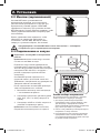
2. Instalación
1
2
3
D
D
E
E
4
F
F
C
B
C
B
A
B
B
A
2.1 Instalación (Rack)
• Use los estantes para rackmount y lo accesorios de instalación incluidos para instalar el
sistema UPS en un rack o estante de 4 postes. Para instalar el sistema UPS en un rack de 2
postes (telecomunicaciones), pida el juego para rackmount en 2 postes de
Tripp Lite (modelo 2POSTRMKITWM, se vende por separado).
• Las instrucciones de este manual son para tipos de racks y estantes comunes y puede que
no sean adecuadas para todas las aplicaciones de montaje. El usuario debe determinar la
idoneidad de los accesorios y los procedimientos antes de la instalación. Si los accesorios o
procedimientos no son apropiados para la aplicación, póngase en contacto con el fabricante
del rack o gabinete para obtener una solución.
Advertencia: El sistema UPS es muy pesado, así que tenga cuidado cuando lo
mueve o lo levanta.
Procedimiento de Instalación en 4 Postes
1
Los ganchos plásticos
A
incluidos soportarán los
estantes
B
para rackmount vacíos hasta que se
instalen los accesorios de instalación
permanentes. Inserte un gancho cerca del centro
del soporte frontal y posterior de cada estante
como se muestra. (Cada soporte frontal tiene
seis orificios y cada soporte posterior posee tres
orificios.) Los ganchos encajarán en su lugar.
Después de colocar los ganchos, expanda cada
estante para que se ajuste con la profundidad de
los rieles del rack vertical. Los ganchos encajarán
en los orificios cuadrados en los rieles del rack
para sostener los estantes. Confirme que los
estantes estén nivelados en todas las direcciones.
Nota: El reborde de soporte de cada estante debe
quedar mirando hacia adentro.
2
Asegure de manera permanente los estantes
B
a los rieles del rack usando los tornillos más
largos que vienen incluidos y las arandelas
C
como se muestra. (Coloque quatro tornillos en
la parte frontal y quatro tornillos en la parte
posterior.) Apriete todos los tornillos antes de
continuar.
Advertencia: No intente instalar el
sistema UPS hasta que se hayan
insertado y apretado los tornillos
necesarios. Los ganchos plásticos no
soportarán el peso del UPS.
3
Una los soportes de montaje
D
a los orificios
de montaje hacia delante del sistema UPS
usando los tornillos más cortos
E
que vienen
incluidos. Las orejas del soporte de montaje
deben mirar hacia adelante.
4
Con la ayuda de un asistente, levante el sistema UPS y deslícelo dentro de los estantes de
montaje. Inserte quatro de los tornillos
F
incluidos a través de las orejas del soporte de
montaje y en los rieles del rack vertical. Apriete todos los tornillos de manera segura.
17-06-040-932882.indb 20 6/29/2017 10:34:36 AM
La page charge ...
La page charge ...
La page charge ...
La page charge ...
La page charge ...
La page charge ...
La page charge ...
La page charge ...
La page charge ...
La page charge ...
La page charge ...
La page charge ...
La page charge ...
La page charge ...
La page charge ...
La page charge ...
La page charge ...
La page charge ...
La page charge ...
La page charge ...
La page charge ...
La page charge ...
La page charge ...
La page charge ...
La page charge ...
La page charge ...
La page charge ...
La page charge ...
La page charge ...
La page charge ...
La page charge ...
La page charge ...
La page charge ...
La page charge ...
La page charge ...
La page charge ...
La page charge ...
La page charge ...
La page charge ...
La page charge ...
La page charge ...
La page charge ...
La page charge ...
La page charge ...
La page charge ...
La page charge ...
La page charge ...
La page charge ...
-
 1
1
-
 2
2
-
 3
3
-
 4
4
-
 5
5
-
 6
6
-
 7
7
-
 8
8
-
 9
9
-
 10
10
-
 11
11
-
 12
12
-
 13
13
-
 14
14
-
 15
15
-
 16
16
-
 17
17
-
 18
18
-
 19
19
-
 20
20
-
 21
21
-
 22
22
-
 23
23
-
 24
24
-
 25
25
-
 26
26
-
 27
27
-
 28
28
-
 29
29
-
 30
30
-
 31
31
-
 32
32
-
 33
33
-
 34
34
-
 35
35
-
 36
36
-
 37
37
-
 38
38
-
 39
39
-
 40
40
-
 41
41
-
 42
42
-
 43
43
-
 44
44
-
 45
45
-
 46
46
-
 47
47
-
 48
48
-
 49
49
-
 50
50
-
 51
51
-
 52
52
-
 53
53
-
 54
54
-
 55
55
-
 56
56
-
 57
57
-
 58
58
-
 59
59
-
 60
60
-
 61
61
-
 62
62
-
 63
63
-
 64
64
-
 65
65
-
 66
66
-
 67
67
-
 68
68


Tripp Lite SmartOnline Le manuel du propriétaire
- Catégorie
- Alimentations sans interruption (UPS)
- Taper
- Le manuel du propriétaire
- Ce manuel convient également à
dans d''autres langues
Documents connexes
-
Tripp Lite SmartOnline UPS Manuel utilisateur
-
Tripp Lite SUINT3000RTXL2U Le manuel du propriétaire
-
-
-
-
Tripp Lite SU750XL Le manuel du propriétaire
-
-
Tripp Lite Single-Phase Online Rack UPS Le manuel du propriétaire
-
-