


EN - English - Instructions manual
1
EN
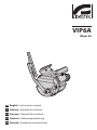
VIP6A
Wiper kit
3 Safety rules
h
The manufacturer declines all responsibility
for any damage caused by an improper use
of the appliances mentioned in this manual.
Furthermore, the manufacturer reserves
the right to modify its contents without any
prior notice. The documentation contained
in this manual has been collected with great
care, the manufacturer, however, cannot
take any liability for its use. The same thing
can be said for any person or company
involved in the creation and production of
this manual.
• The device must be installed only and exclusively
by qualied technical personnel.
• Before any technical work on the appliance,
disconnect the power supply.
• Do not use power supply cables that seem worn
or old.
• Never, under any circumstances, make any
changes or connections that are not shown in
this handbook: improper use of the appliance
can cause serious hazards, risking the safety of
personnel and of the installation.
• Use only original spare parts. Not original spare
parts could cause re, electrical discharge or other
hazards.
• Before proceeding with installation check the
supplied material to make sure it corresponds
to the order specication by examining the
identication labels ("4.2 Product markings", page1).
4 Identification
4.1 Product description and type
designation
Wiper kit which can be directly installed on the
housing body. It completes the support for the pump
washing injector. Available in 24Vac and 230Vac
versions, 7W max. Available for HEG series housing.
4.2 Product markings
See the label attached to the outside of the package.
1 About this manual
Before installing and using this unit, please read this
manual carefully. Be sure to keep it handy for later
reference.
1.1 Typographical conventions
g
DANGER!
High level hazard.
Risk of electric shock. Disconnect the
power supply before proceeding with any
operation, unless indicated otherwise.
h
WARNING!
Medium level hazard.
This operation is very important for the
system to function properly. Please read
the procedure described very carefully and
carry it out as instructed.
j
INFO
Description of system specications.
We recommend reading this part carefully
in order to understand the subsequent
stages.
2 Notes on copyright and
information on trademarks
The quoted names of products or companies are
trademarks or registered trademarks.
ENGLISH

EN - English - Instructions manual
2
6 Assembling and
installing
h
Only specialised personnel should be
allowed to assemble and install the device.
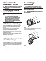
6.1 Installation
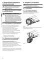
6.1.1 Installing the wiper kit on the
housing.
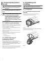
Remove the front ange on the housing by
unscrewing the three front screws.
Fig. 01
Insert the wiper body by slotting the slide onto the
prole of the housing body.
Fig. 02
5 Preparing the product
for use
h
Any change that is not expressly approved
by the manufacturer will invalidate the
guarantee.
5.1 Safety precautions before
use
g
In the 115/230Vac powered conguration
it is necessary to insert a 1 0 unipolar
main switch (open contact distance
d>3mm) upstream on the power line. This
switch should be used to disconnect the
power supply before carrying out any
maintenance operation or before opening
the housing.
5.2 Contents and unpacking
When the product is delivered, make sure that the
package is intact and that there are no signs that it
has been dropped or scratched.
If there are obvious signs of damage, contact the
supplier immediately.
Keep the packaging in case you need to send the
product for repairs.
Check the contents to make sure they correspond
with the list of materials as below:
• Wiper kit
• Instructions manual
5.3 Safely disposing of
packaging material
The packaging material can all be recycled. The
installer technician will be responsible for separating
the material for disposal, and in any case for
compliance with the legislation in force where the
device is to be used.
Bear in mind that if the material has to be returned
due to a fault, using the original packaging for its
transport is strongly recommended.

EN - English - Instructions manual
3
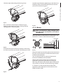
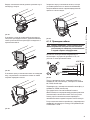
Lock the wiper body by tightening up the dowels on
the xing slide so that the blade exerts the correct
pressure on the housing glass.
Fig. 06
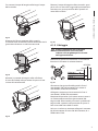
6.1.2 Wiring
h
Make sure the power supply voltage used is
the same shown on the plate on the back of
the appliance.
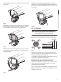
Make the electrical connections on the female 3+PE
connector as shown in the electrical diagram.
PHASE
NEUTRAL
SWITCH
PERM (01)
COM (02)
SW (03)
EARTH
01 02
03
Fig. 07
Power the wiper by connecting the phase to terminal
03 (SW) on the connector and neutral to terminal 02
(COM) on the connector.
Use an external button to connect the phase to
terminal 01 (PERM) on the connector.
Keeping the external button pressed will cause
continuous operation (permanent) of the wiper.
Releasing the button will take the wiper blade to the
rest position on the left side of the housing window.
If a receiver is used, connect terminal 03 of the
connector to the SW output on the receiver, 01 to
PERM and 02 to COM.
Slide the wiper body along the housing body.
Fig. 03
Re-assemble the front ange on the housing by
tightening the three front screws, making sure the
sealing gasket is seated properly.
Fig. 04
Assemble the wiper blade on the output shaft, xing
it in the rest position on the left side of the glass front.
Fig. 05

EN - English - Instructions manual
4
10 Technical drawings
j
The values are in millimeters.
R182
86
114
217
144
209
99
Fig. 8 VIP6A
7 Instructions for normal
operation
h
Do not use the wiper when the outside
temperature is below 0°C or in case of ice.
8 Disposal of waste
materials
n
This symbol mark and recycle system
are applied only to EU countries and not
applied to the countries in the other area of
the world.
Your product is designed and manufactured with
high quality materials and components which can be
recycled and reused.
This symbol means that electrical and electronic
equipment, at their end-of-life, should be disposed of
separately from your household waste.
Please dispose of this equipment at your local
Community waste collection or Recycling centre.
In the European Union there are separate collection
systems for used electrical and electronic products.
9 Technical data
9.1 General
Enclosure from reinforced polypropylene
Wiper blade constructed from stainless steel/aluminium
RAL9002 colour
IP66
Dimensions (WxHxL): 99x114x209mm (3.8x4.4x8.2 in)
(not comprehensive of blade)
Unit weight: 0.7kg / 1.5lb
Connector 3+1 PINS
IN 230Vac, consumption 7W max
IN 24Vac, consumption 7W max
Operating temperature: -20°C / +60°C (-4°F / +140°F)
Supplied with instruction manual
EAC certification

IT - Italiano - Manuale di istruzioni
1
IT
ITALIANO
3 Norme di sicurezza
h
Il produttore declina ogni responsabilità
per eventuali danni derivanti da un uso
improprio delle apparecchiature menzionate
in questo manuale. Si riserva inoltre il diritto
di modicarne il contenuto senza preavviso.
Ogni cura è stata posta nella raccolta e nella
verica della documentazione contenuta
in questo manuale, tuttavia il produttore
non può assumersi alcuna responsabilità
derivante dall'utilizzo della stessa. Lo stesso
dicasi per ogni persona o società coinvolta
nella creazione e nella produzione di questo
manuale.
• L'installazione e la manutenzione del dispositivo
deve essere eseguita solo da personale tecnico
qualicato.
• Prima di eettuare interventi tecnici
sull'apparecchio togliere l'alimentazione elettrica.
• Non utilizzare cavi di alimentazione con segni di
usura o invecchiamento.
• Non eettuare per nessun motivo alterazioni o
collegamenti non previsti in questo manuale:
l'uso di apparecchi non idonei può portare a
gravi pericoli per la sicurezza del personale e
dell'impianto.
• Utilizzare solo parti di ricambio originali. Pezzi di
ricambio non originali potrebbero causare incendi,
scariche elettriche o altri pericoli.
• Prima di procedere con l'installazione controllare
che il materiale fornito corrisponda alle speciche
richieste esaminando le etichette di marcatura ("4.2
Marcatura del prodotto", pagina1).
4 Identificazione
4.1 Descrizione e designazione
del prodotto
Kit tergicristallo installabile direttamente sul corpo
custodia. Integra il supporto per l’iniettore di lavaggio
proveniente dalla pompa. Disponibile nelle versioni
24Vac e 230Vac, 7W max. Disponibile per le custodie
della serie HEG.
4.2 Marcatura del prodotto
Vedere l’etichetta posta sull’esterno dell’imballo.
1 Informazioni sul presente
manuale
Prima di installare e utilizzare questa unità, leggere
attentamente questo manuale. Conservare questo
manuale a portata di mano come riferimento futuro.
1.1 Convenzioni tipograche
g
PERICOLO!
Pericolosità elevata.
Rischio di scosse elettriche. Togliere
l'alimentazione prima di procedere con le
operazioni, salvo diversa indicazione.
h
ATTENZIONE!
Pericolosità media.
L'operazione è molto importante per il
corretto funzionamento del sistema. Si
prega di leggere attentamente la procedura
indicata e di eseguirla secondo le modalità
previste.
j
INFO
Descrizione delle caratteristiche del
sistema.
Si consiglia di leggere attentamente per
comprendere le fasi successive.
2 Note sul copyright e
informazioni sui marchi
commerciali
I nomi di prodotto o di aziende citati sono marchi
commerciali o marchi commerciali registrati
appartenenti alle rispettive società.
VIP6A
Kit tergicristallo

IT - Italiano - Manuale di istruzioni
2
6 Assemblaggio e
installazione
h
L'assemblaggio e l'installazione vanno
eseguiti solo da personale specializzato.
6.1 Installazione
6.1.1 Installazione del kit tergicristallo
sulla custodia
Smontare la angia anteriore della custodia svitando
le tre viti frontali.
Fig. 01
Inserire il corpo tergicristallo inlando la slitta sul
prolo del corpo della custodia.
Fig. 02
5 Preparazione del
prodotto per l'utilizzo
h
Qualsiasi cambiamento non espressamente
approvato dal costruttore fa decadere la
garanzia.
5.1 Precauzioni di sicurezza
prima dell’utilizzo
g
In congurazione alimentata a 115/230Vac
occorre inserire sulla linea di alimentazione,
a monte, un interruttore generale unipolare
1 0 (distanza apertura dei contatti
d>3mm). Tale interruttore deve essere
utilizzato come mezzo di separazione
dell’alimentazione prima di eseguire
qualsiasi operazione di manutenzione o
apertura della custodia.
5.2 Contenuto e disimballaggio
Alla consegna del prodotto vericare che l'imballo
sia integro e non abbia segni evidenti di cadute o
abrasioni.
In caso di evidenti segni di danno all'imballo
contattare immediatamente il fornitore.
Conservare l'imballo nel caso sia necessario inviare il
prodotto in riparazione.
Controllare che il contenuto sia rispondente alla lista
del materiale sotto indicata:
• Kit tergicristallo
• Manuale di istruzioni
5.3 Smaltimento in sicurezza dei
materiali di imballaggio
I materiali d'imballo sono costituiti interamente da
materiale riciclabile. Sarà cura del tecnico installatore
smaltirli secondo le modalità di raccolta dierenziata
o comunque secondo le norme vigenti nel Paese di
utilizzo.
Si ricorda comunque che in caso di ritorno di
materiale con malfunzionamenti è consigliato
l'imballaggio originale per il trasporto.

IT - Italiano - Manuale di istruzioni
3
Bloccare il corpo del tergicristallo avvitando i grani
posti sulla sua slitta di ssaggio nella posizione che
consenta una giusta pressione della spazzola sul
vetro della custodia.
Fig. 06
6.1.2 Cablaggio
h
Prestare attenzione che la tensione
di alimentazione usata sia quella
indicata sulla targhetta posta sul retro
dell’apparecchiatura.
Eettuare le connessioni elettriche sul connettore
femmina 3+PE come da schema elettrico.
PHASE
NEUTRAL
SWITCH
PERM (01)
COM (02)
SW (03)
EARTH
01 02
03
Fig. 07
Alimentare il tergicristallo collegando la fase al
morsetto 03 (SW) del connettore e il neutro al
morsetto 02 (COM) del connettore.
Collegare tramite un pulsante esterno la fase al
morsetto 01 (PERM) del connettore.
Mantenendo premuto il pulsante esterno si otterrà
un funzionamento continuo (permanente) del
tergicristallo. Rilasciando il pulsante la spazzola del
tergicristallo si porterà nella posizione di riposo al
lato sinistro del vetro della custodia.
Nel caso si utilizzi un ricevitore collegare il morsetto
03 del connettore all’uscita SW del ricevitore, 01 a
PERM e 02 a COM.
Far scorrere il corpo del tergicristallo lungo il corpo
della custodia.
Fig. 03
Rimontare la angia anteriore della custodia
avvitando le tre viti frontali facendo attenzione che la
guarnizione di tenuta sia nella corretta sede.
Fig. 04
Montare la spazzola del tergicristallo sull’albero
d’uscita ssandola nella posizione di riposo sul lato
sinistro del vetro frontale.
Fig. 05

IT - Italiano - Manuale di istruzioni
4
10 Disegni tecnici
j
I valori espressi sono in millimetri.
R182
86
114
217
144
209
99
Fig. 8 VIP6A
7 Istruzioni di
funzionamento ordinario
h
Non utilizzare il tergicristallo quando la
temperatura esterna è inferiore agli 0°C o in
presenza di ghiaccio.
8 Smaltimento dei rifiuti
n
Questo simbolo e il sistema di riciclaggio
sono validi solo nei paesi dell'EU e non
trovano applicazione in altri paesi del
mondo.
Il vostro prodotto è stato costruito da materiali e
componenti di alta qualità, che sono riutilizzabili o
riciclabili.
Prodotti elettrici ed elettronici che portano questo
simbolo alla ne dell'uso devono essere smaltiti
separatamente dai riuti casalinghi.
Vi preghiamo di smaltire questo apparecchio in un
Centro di raccolta o in un'Ecostazione.
Nell'Unione Europea esistono sistemi di raccolta
dierenziata per prodotti elettrici ed elettronici.
9 Dati tecnici
9.1 Generale
Corpo in polipropilene rinforzato
Spazzola in acciaio Inox/alluminio
Colore RAL9002
IP66
Dimensioni (WxHxL): 99x114x209mm (non comprensivo
di spazzola)
Peso unitario: 0.7kg
Connettore 3+1 PIN
IN 230Vac, consumo 7W max
IN 24Vac, consumo 7W max
Temperatura di esercizio: -20°C / + 50°C
Fornito con manuale di istruzioni
Certificazione EAC

FR - Français - Manuel d'instructions
1
FR
3 Normes de securité
h
Le producteur décline toute responsabilité
pour les dommages éventuels dus à une
utilisation non appropriée des appareils
mentionnés dans ce manuel. On réserve
en outre le droit d’en modier le contenu
sans préavis. La documentation contenue
dans ce manuel a été rassemblée et vériée
avec le plus grand soin, cependant, le
producteur ne peut pas s’assumer aucune
responsabilité dérivante de l’emploi de
celle là. La même chose vaut pour chaque
personne ou société impliquées dans la
création et la production de ce manuel.
• L’installation et l’entretien du dispositif doivent
être exclusivement être eectués par un personnel
technique qualié.
• Sectionner l’alimentation électrique avant toute
intervention technique sur l’appareil.
• Ne pas utiliser de câbles d’alimentation usés ou
endommagés.
• Ne procéder sous aucun prétexte à des
modications ou des connexions non prévues
dans ce manuel: l’utilisation d’appareils non
adéquats peut comporter des dangers graves pour
la sécurité du personnel et de l’installation.
• Utiliser uniquement des pièces de rechange
d’origine. Les pièces non d’origine peuvent être
source d’incendies, de choc électrique ou autres.
• Avant de procéder à l’installation, contrôler que
le matériel fourni correspond à la commande
et examiner les étiquettes de marquage ("4.2
Marquage du produit", page1).
4 Identification
4.1 Description et désignation
du produit
Kit essuie-glace, à installer directement sur le corps
du caisson, comprenant le gliceur de lavage qui
vient de la pompe du lave glace; disponible dans les
versions 24Vac et 230Vac, 7W max. Pour les caissons
de la série HEG.
4.2 Marquage du produit
Voir l’étiquette sur l’extérieur de l’emballage.
1 À propos de ce mode
d’emploi
Avant d’installer et d’utiliser cet appareil, veuillez
lire attentivement ce mode d’emploi. Conservez-le à
portée de main pour pouvoir vous y reporter en cas
de besoin.
1.1 Conventions typographiques
g
DANGER!
Risque élevé.
Risque de choc électrique. Sauf indication
contraire, sectionner l’alimentation avant
de procéder à toute opération.
h
ATTENTION!
Risque moyen.
Opération extrêmement importante en vue
d’un fonctionnement correct du système;
lire avec attention les opérations indiquées
et s’y conformer rigoureusement.
j
REMARQUE
Description des caractéristiques du
système.
Il est conseillé de procéder à une
lecture attentive pour une meilleure
compréhension des phases suivantes.
2 Notes sur le copyright
et informations sur les
marques de commerce
Les noms de produit ou de sociétés cités sont des
marques de commerce ou des marques de commerce
enregistrées.
VIP6A
Kit essuie-glace
FRANÇAIS

FR - Français - Manuel d'instructions
2
6 Assemblage et
installation
h
L’assemblage et l’installation doivent
exclusivement être eectués par un
personnel spécialisé.
6.1 Installation
6.1.1 Installation du kit essuie-glaces
sur le caisson
Démonter la bride avant du caisson en dévissant les
trois vis frontales.
Fig. 01
Insérer le corps de l'essuie-glace en enlant la
glissière sur le prol du corps du caisson.
Fig. 02
5 Préparation du produit
en vue de l’utilisation
h
Toute modication non approuvée
expressément par le fabricant entraînera
l’annulation de la garantie.
5.1 Précautions de sécurité
avant l’utilisation
g
En cas d’alimentation à 115/230Vac,
installer en amont de la ligne
d’alimentation un interrupteur général
unipolaire 1 0 (distance d’ouverture des
contacts d>3mm). Cet interrupteur doit
être utilisé comme moyen de séparation
de l’alimentation avant de procéder à
l’ouverture du caisson ou à toute opération
d’entretien.
5.2 Contenu et déballage
Lors de la livraison du produit, vérier que
l’emballage est en bon état et l’absence de tout signe
évident de chute ou d’abrasion.
En cas de dommages évidents, contacter
immédiatement le fournisseur.
Conserver l’emballage en cas de nécessité
d’expédition du produit pour réparation.
Contrôler que le contenu correspond à la liste
matériel indiquée ci-dessous:
• Kit essuie-glace
• Manuel d'instructions
5.3 Élimination sans danger des
matériaux d’emballage
Le matériel d’emballage est entièrement composé
de matériaux recyclables. Le technicien chargé de
l’installation est tenu de l’éliminer conformément aux
dispositions en matière de collecte sélective et selon
les normes en vigueur dans le pays d’utilisation.
En cas de dysfonctionnement et de retour de
matériel, il est conseillé d’utiliser l’emballage original
pour le transport.

FR - Français - Manuel d'instructions
3
Bloquer le corps de l'essuie-glace en vissant les vis
sans tête sur la glissière de xation dans une position
permettant une pression adéquate du balai sur la vitre
du caisson.
Fig. 06
6.1.2 Cablage
h
Contrôler que la tension d'alimentation
utilisée correspond à celle indiquée sur la
plaque xée à l'arrière de l'appareil.
Procéder aux connexions électriques du connecteur
femelle 3+PE conformément au schéma électrique.
PHASE
NEUTRAL
SWITCH
PERM (01)
COM (02)
SW (03)
EARTH
01 02
03
Fig. 07
Mettre l'essuie-glace sous tension en connectant la
phase à la borne 03 (SW) du connecteur, et le neutre
à la borne 02 (COM) du connecteur.
Au moyen d'un poussoir externe, connecter la phase
à la borne 01 (PERM) du connecteur.
Maintenir le poussoir externe enfoncé pour un
fonctionnement de l'essuie-glace en continu
(permanent). Relâcher le poussoir pour placer le balai
de l'essuie-glace en position de repos sur le côté
gauche du verre du caisson.
En cas d'utilisation d'un récepteur, brancher la borne
03 du connecteur à la sortie SW du récepteur, la 01 à
PERM et la 02 à COM.
Faire glisser le corps de l'essuie-glace le long du corps
du caisson.
Fig. 03
Remonter la bride avant du caisson et visser les trois
vis frontales en ayant soin que les garnitures soient
correctement installées dans leurs logements.
Fig. 04
Monter le balai de l'essuie-glace sur l'arbre en sortie
en le xant en position de repos sur le côté gauche
du verre frontal.
Fig. 05

FR - Français - Manuel d'instructions
4
10 Dessins techniques
j
Les valeurs sont entendues en millimètres.
R182
86
114
217
144
209
99
Fig. 8 VIP6A
7 Instructions de
fonctionnement courant
h
Ne pas utiliser l’essuie-glace lorsque la
température extérieure est inférieure à 0°C
ou en cas de glace.
8 Élimination des déchets
n
Ce symbole et le système de recyclage ne
sont appliqués que dans les pays UE et non
dans les autres pays du monde.
Votre produit est conçu et fabriqué avec des matèriels
et des composants de qualité supérieure qui peuvent
être recyclés et réutilisés.
Ce symbole signie que les équipements électriques
et électroniques en n de vie doivent être éliminés
séparément des ordures ménagères.
Nous vous prions donc de coner cet équipement à
votre Centre local de collecte ou Recyclage.
Dans l’Union Européenne, il existe des systèmes
sélectifs de collecte pour les produits électriques et
électroniques usagés.
9 Données techniques
9.1 Généralités
Corps en polypropylène renforcé
Balai en acier Inox / aluminium
Couleur RAL9002
IP66
Dimensions (WxHxL): 99x114x209mm (sans balai)
Poids net: 0.7kg
Connecteur 3+1 PINS
IN 230Vac, consommation 7W max
IN 24Vac, consommation 7W max
Température d’exercice: -20°C / +60°C
Livré avec un manuel d’instructions
Certification EAC

DE - Deutsch - Bedienungslanleitung
1
DE
3 Sicherheitsnormen
h
Der Hersteller lehnt jede Haftung für
eventuelle Schäden ab, die aufgrund
unsachgemäßer Anwendung der in diesem
Handbuch erwähnten Geräte entstanden
ist. Ferner behält er sich das Recht vor, den
Inhalt ohne Vorkündigung abzuändern.
Die Dokumentation in diesem Handbuch
wurde sorgfältig ausgeführt und überprüft,
dennoch kann der Hersteller keine Haftung
für die Verwendung übernehmen. Dasselbe
gilt für jede Person oder Gesellschaft, die
bei der Schaung oder Produktion von
diesem Handbuch miteinbezogen ist.
• Die Installation und Wartung der Vorrichtung ist
technischen Fachleuten vorbehalten.
• Vor technischen Eingrien am Gerät muss die
Stromversorgung unterbrochen werden.
• Es dürfen keine Versorgungskabel mit Verschleiß-
oder Alterungsspuren verwendet werden.
• Unter keinen Umständen dürfen Veränderungen
oder Anschlüsse vorgenommen werden, die
in diesem Handbuch nicht genannt sind: Der
Gebrauch ungeeigneten Geräts kann die Sicherheit
des Personals und der Anlage schwer gefährden.
• Es dürfen nur Original-Ersatzteile verwendet
werden. Nicht originale Ersatzteile können zu
Bränden, elektrischen Entladungen oder anderen
Gefahren führen.
• Vor der Installation ist anhand des
Kennzeichnungsschildes nachzuprüfen, ob das
gelieferte Material die gewünschten Eigenschaften
aufweist ("4.2 Kennzeichnung des Produkts", Seite1).
4 Identifizierung
4.1 Beschreibung und
Bezeichnung des Produktes
Wischer-Kit, der direkt auf den Körper des Gehäuses
installiert werden kann. Der Wischer beinhaltet die
Waschspritzdüse der Pumpe. 24Vac- und 230Vac-
Ausführung, 7W max, lieferbar. Für HEG- Gehäuse.
4.2 Kennzeichnung des Produkts
Siehe das Schild außen auf der Verpackung.
1 Allgemeines
Lesen Sie bitte vor dem Installieren und dem
Verwenden dieses Gerätes die Bedienungsanleitung
sorgfältig durch. Bewahren Sie sie zum späteren
Nachschlagen auf.
1.1 Schreibweisen
g
GEFAHR!
Erhöhte Gefährdung.
Stromschlaggefahr. Falls nichts anderes
angegeben, unterbrechen Sie die
Stromversorgung, bevor die beschriebenen
Arbeiten durchgeführt werden.
h
ACHTUNG!
Mittlere Gefährdung.
Der genannte Vorgang hat große
Bedeutung für den einwandfreien Betrieb
des Systems: es wird gebeten, sich die
Verfahrensweise anzulesen und zu
befolgen.
j
ANMERKUNG
Beschreibung der Systemmerkmale.
Eine sorgfältige Lektüre wird empfohlen,
um das Verständnis der folgenden Phasen
zu gewährleisten.
2 Anmerkungen
zum Copyright und
Informationen zu den
Handelsmarken
Die angeführten Produkt- oder Firmennamen sind
Handelsmarken oder eingetragene Handelsmarken.
VIP6A
Wischer-Kit
DEUTSCH

DE - Deutsch - Bedienungslanleitung
2
6 Zusammenbau und
Installation
h
Zusammenbau und Installation sind
Fachleuten vorbehalten.
6.1 Installation
6.1.1 Montage des Scheibenwischer-
Kits an das Gehäuse
Den vorderen Gehäuseansch durch Lösen der drei
vorderen Schrauben entfernen.
Fig. 01
Den Korpus des Wischers so einsetzen, daß der
Schlitten auf dem Prol des Gehäusekorpus gleitet.
Fig. 02
5 Vorbereitung des
Produktes auf den
Gebrauch
h
Jede vom Hersteller nicht ausdrücklich
genehmigte Veränderung führt zum Verfall
der Gewährleistungsrechte.
5.1 Sicherheitsvorkehrungen vor
dem Gebrauch
g
In der Konguration mit einer
Versorgungsspannung von 115/230Vac
muß der Versorgungsleitung ein einpoliger
Hauptschalter vorgeschaltet werden 1 0
(Kontaktabstand d>3mm). Dieser Schalter
muß zur Trennung der Stromversorgung
betätigt werden, bevor das Gehäuse
gewartet oder anderweitig geönet wird.
5.2 Inhalt und Entfernen der
Verpackung
Bei der Lieferung des Produktes ist zu prüfen, ob die
Verpackung intakt ist oder oensichtliche Anzeichen
von Stürzen oder Abrieb aufweist.
Bei oensichtlichen Schadensspuren an der
Verpackung muss umgehend der Lieferant
verständigt werden.
Bewahren Sie die Verpackung auf für den Fall, dass
das Produkt zur Reparatur eingesendet werden muss.
Prüfen Sie, ob der Inhalt mit der nachstehenden
Materialliste übereinstimmt:
• Wischer-Kit
• Bedienungslanleitungen
5.3 Sichere Entsorgung der
Verpackungsmaterialien
Die Verpackungsmaterialien sind vollständig
wiederverwertbar. Es ist Sache des
Installationstechnikers, sie getrennt, auf jeden
Fall aber nach den geltenden Vorschriften des
Anwendungslandes zu entsorgen.
Es wird nochmals empfohlen, mit Fehlfunktionen
behaftetes Material in der Originalverpackung
zurückzusenden.

DE - Deutsch - Bedienungslanleitung
3
Der Wischerkörper wird xiert durch
Anschrauben der Gewindestifte, die sich auf dem
Befestigungsschlitten benden. Die Position sollte
den richtigen Druck der Bürste auf das Gehäuseglas
gewährleisten.
Fig. 06
6.1.2 Verkabelung
h
Achten Sie darauf, daß die vorhandene
Versorgungsspannung mit den Angaben
auf dem Typenschild übereinstimmt, das
auf der Rückseite des Gerätes sitzt.
Die Stromanschlüsse an die Steckbuchse 3-PE werden
nach dem Schaltbild vorgenommen.
PHASE
NEUTRAL
SWITCH
PERM (01)
COM (02)
SW (03)
EARTH
01 02
03
Fig. 07
Den Scheibenwischer mit Strom versorgen, indem
man die Phase an Klemme 03 (SW) der Buchse und
den Nulleiter an Klemme 02 (COM) der Buchse anlegt.
Über einen externen Knopf wird die Phase mit der
Klemme 01 (PERM) der Buchse verbunden.
Bei dauerhaftem Drücken des externen Knopfes
läuft der Scheibenwischer kontinuierlich
(durchgehend). Läßt man den Knopf los, wird die
Scheibenwischerbürste in ihre Ruhestellung links
vom Gehäuseglas geführt.
Falls ein Empfänger benutzt wird, wird Klemme 03
der Buchse mit dem Ausgang SW des Empfangsteils
verbunden, Klemme 01 mit PERM und Klemme 02
mit COM.
Den Korpus des Wischers entlang des Gehäusekorpus
gleiten lassen.
Fig. 03
Den Vorderansch des Gehäuses wieder anbringen
und die drei Vorderschrauben festziehen. Achten Sie
darauf, daß die Dichtung richtig sitzt.
Fig. 04
Die Wischerbürste so auf die Abtriebswelle
montieren, daß sie in Ruhestellung links vom
Frontglas sitzt.
Fig. 05

DE - Deutsch - Bedienungslanleitung
4
10 Technische Zeichnungen
j
Maßangabe in Millimeter.
R182
86
114
217
144
209
99
Fig. 8 VIP6A
7 Anleitung für den
normalen Betrieb
h
Der Scheibenwischer ist bei
Aussentemperaturen unter 0°C oder bei
Glas nicht zu betätigen
8 Müllentsorgungsstellen
n
Dieses Symbol und das entsprechende
Recycling-System gelten nur für EULänder
und nden in den anderen Ländern der
Welt keine Anwendung.
Ihr Produkt wurde entworfen und hergestellt
mit qualitativ hochwertigen Materialien und
Komponenten, die recycelt und wiederverwendet
werden können.
Dieses Symbol bedeutet, daß elektrische und
elektronische Geräte am Ende ihrer Nutzungsdauer
von Hausmüll getrennt entsorgt werden sollen.
Bitte entsorgen Sie dieses Gerät bei Ihrer örtlichen
Sammelstelle oder im Recycling Centre.
In der Europäischen Union gibt es unterschiedliche
Sammelsysteme für Elektrik- und Elektronikgeräte.
9 Technische Daten
9.1 Allgemeines
Körper aus verstärktem Polypropylen
Bürste aus rostfreiem Stahl / Aluminium
Farbe RAL9002
IP66
Abmessungen (WxHxL): 99x114x209mm (ohne Bürste)
Einheitsgewicht: 0.7kg
3+1 PIN- Verbinder
IN 230Vac, Verbrauch 7W max
IN 24Vac, Verbrauch 7W max
Betriebstemperatur: -20°C / +60°C
Im Lieferumfang enthalten Betriebsanleitung
EAC-Zertifizierung

RU - Русский - Учебник инструкции
1
РУССКИЙ
1
RU
3 Правила техники безопасности
h
Производитель снимает с себя всякую
ответственность за ущерб, причиненный в
результате использования оборудования не
по назначению и без соблюдения инструкций,
изложенных в данном руководстве.
Производитель также оставляет за собой право
на внесение изменений без предварительного
уведомления. При составлении и проверке
документации настоящего руководства
были включены все необходимые меры
предосторожности, тем не менее, производитель
снимает с себя ответственность за результаты ее
использования. То же самое относится к любому
лицу или компании, участвующим в создании и
публикации данного руководства.
• Установка и техобслуживание прибора должно выполняться
только квалифицированным техническим персоналом.
• Перед выполнением технических операций на
приборе отключить электропитание.
• Не использовать силовые кабели с признаками
износа или старения.
• Ни в коем случае не выполнять непредусмотренные данным
руководством соединения или изменения: использование
несоответствующих приборов может стать причиной
серьёзных рисков для безопасности персонала и системы.
• Используйте только оригинальные запасные
части. Использование неоригинальных запасных
частей может привести к пожарам, электрическим
разрядам или другим опасностям.
• До начала установки проверьте, изучив для этого
маркировочные этикетки, чтобы поставленный
материал соответствовал определённым требованиям
("4.2 Маркировка изделия", страница1)
.
4 Идентификация
4.1 Описание и назначение изделия
Комплект стеклоочистителя, устанавливаемый
непосредственно в корпус кожуха. Включает в
себя опору для инжектора промывки от насоса.
Доступны две версии 24 В пер.т. и 230 В пер.т.,
макс. 7 Вт. Доступны для кожухов серии HEG.
4.2 Маркировка изделия
Смотрите клейкую этикету на внешней стороне упаковки.
1 Информация о данном
руководстве
Перед установкой и использованием данного
устройства необходимо внимательно прочитать
настоящее руководство. Хранить данное
руководство под рукой для возможности
обращения в будущем.
1.1 Условные обозначения
шрифтами
g
ОПАСНО!
Повышенная опасность.
Опасность удара электрическим током.
Если не указано иное, отключите
питание, прежде чем приступить к
выполнению операций.
h
ВНИМАНИЕ!
Средняя опасность.
Очень важная операция для правильной
работы системы. Рекомендуется
внимательно прочитать указанную
процедуру и следовать ей в
предусмотренном порядке.
j
ИНФО
Описание характеристик системы.
Рекомендуется внимательно прочитать,
чтобы понять последующие этапы.
2 Примечания об
авторских правах и
информация о торговых
марках
Наименования продукта и указанных компаний
являются зарегистрированными торговыми
марками, принадлежащими соответствующим
предприятиям.
VIP6A
Комплект стеклоочистителя

RU - Русский - Учебник инструкции
22
6 Сборка и установка
h
Монтаж и установка оборудования
должны выполняться только
квалифицированным персоналом.
6.1 Установка
6.1.1 Установка комплекта
стеклоочистителя на кожух.
Демонтировать передний фланец кожуха,
отвинтив три передних винта.
рис. 01
Ввести корпус стеклоочистителя, введя полос на
профиль корпуса кожуха.
рис. 02
5 Подготовка изделия к
использованию
h
Любое изменение, выполненное без
разрешения изготовителя, ведёт к
потере гарантии.
5.1 Меры безопасности перед
использованием
g
В конфигурации с 115/230 В перем.
тока необходимо установить на линии
питания вверху одноконтактный
главный выключатель 1 0 (расстояние
открытия контактов d > 3 мм). Данный
выключатель следует использовать для
отключения питания перед выполнением
любого техобслуживания или открытия
предохранительного кожуха.
5.2 Содержимое и распаковка
При поставке изделия убедитесь в том, что
упаковка не повреждена и не имеет явных
признаков падений или царапин.
В случае повреждения упаковки следует
немедленно обратиться к поставщику.
Храните упаковку на случай, если необходимо
отправка изделия для ремонта.
Убедитесь в том, что содержимое соответствует
списку материалов, приведённому ниже:
• Комплект стеклоочистителя
• Руководство с инструкциями
5.3 Безопасная утилизация
упаковочных материалов
Упаковка полностью состоит из
перерабатываемого материала. Техник,
выполняющий установку, должен переработать
их в отходы в соответствии с правилами
дифференцированного сбора или, в любом
случае, в соответствии с действующими в стране
использования стандартами.
Напоминаем, что в случае возврата неисправного
изделия рекомендуется сохранить оригинальную
упаковку для транспортировки.
La page est en cours de chargement...
La page est en cours de chargement...
La page est en cours de chargement...
La page est en cours de chargement...
-
 1
1
-
 2
2
-
 3
3
-
 4
4
-
 5
5
-
 6
6
-
 7
7
-
 8
8
-
 9
9
-
 10
10
-
 11
11
-
 12
12
-
 13
13
-
 14
14
-
 15
15
-
 16
16
-
 17
17
-
 18
18
-
 19
19
-
 20
20
-
 21
21
-
 22
22
-
 23
23
-
 24
24


dans d''autres langues
- italiano: Videotec VIP6A Manuale utente
- English: Videotec VIP6A User manual
- Deutsch: Videotec VIP6A Benutzerhandbuch
- русский: Videotec VIP6A Руководство пользователя
Documents connexes
-
Videotec VIPNX Manuel utilisateur
-
-
-
-
-
-
-
Videotec ULISSE2 Manuel utilisateur
-