Harmonic ProStream 1000 6.8 Guide d'installation
- Taper
- Guide d'installation

ProStream 1000
Stream Processing Platform
RELEASE 6.8
Installation Guide
Rev A

© 2015 Harmonic Inc. All rights reserved. 2
March 2015
Copyright © 2000—2015 Harmonic Inc. All rights reserved. Omneon, and the Omneon logo are trademarks of Harmonic Inc.
© 2015 Harmonic Inc. All rights reserved. Harmonic, the Harmonic logo, [all other Harmonic products mentioned] are trademarks, registered trademarks or
service marks of Harmonic Inc. in the United States and other countries. Dolby, Dolby Digital, Dolby Digital Plus and Dolby E are registered trademarks of
Dolby Laboratories. Implementations of AAC and HE-AAC by Fraunhofer IIS. Other company, product and service names mentioned herein may be
trademarks or service marks of their respective owners. All product and application features and specifications are subject to change at Harmonic’s sole
discretion at any time and without notice.
Disclaimer
Harmonic reserves the right to alter the equipment specifications and descriptions in this publication without prior notice. No part of this publication shall be
deemed to be part of any contract or warranty unless specifically incorporated by reference into such contract or warranty. The information contained herein
is merely descriptive in nature, and does not constitute a binding offer for sale of the product described herein. Harmonic assumes no responsibility or
liability arising from the use of the products described herein, except as expressly agreed to in writing by Harmonic. The use and purchase of this product do
not convey a license under any patent rights, copyrights, trademark rights, or any intellectual property rights of Harmonic. Nothing hereunder constitutes a
representation or warranty that using any products in the manner described herein will not infringe any patents of third parties.
Third-Party Product Trademarks
Adobe® After Effects®, Photoshop®, Flash® Professional, Premiere®
Avid® Media Composer®
Dolby® E, Dolby Digital, Dolby Digital Plus
Jünger Audio™
Apple® QuickTime®
Microsoft® Mediaroom®
Microsoft® PlayReady®
DOCSIS® 3.0
Start Over® TV
Third-Party Copyright Notes
Dolby is a registered trademark of Dolby Laboratories. Dolby Digital, Dolby Digital Plus, Dolby Pulse, aacPlus, AC-3, and Dolby E are trademarks of Dolby
Laboratories.
Level Magic and Jünger are trademarks of Jünger Audio Studiotechnik GmbH.
MPEG Audio technology licensed from Fraunhofer IIS http://www.iis.fraunhofer.de/amm/
PitchBlue® is a registered trademark of Vigor Systems.
QuickTime and the QuickTime logo are trademarks or registered trademarks of Apple Computer, Inc., used under license therefrom.
Trademark Acknowledgments
Harmonic and all Harmonic product names are trademarks of Harmonic Inc. All other trademarks are the property of their respective owners.
The software described in this document is furnished under a license agreement or nondisclosure agreement. The software may be used or copied only in
accordance with the terms of those agreements.
May be covered by one or more of U.S. Patents No. 6,571,351; 6,696,996; 6,545,721; 6,574,225; 6,895,003; 6,522,649; 6,643,702; foreign counterparts
and pending patent applications.
This system is distributed with certain other software that may require disclosure or distribution of licenses, copyright notices, conditions of use, disclaimers
and/or other matter. Use of this system or otherwise fulfilling their conditions constitutes your acceptance of them, as necessary. Copies of such licenses,
notices, conditions, disclaimers and/or other matter are available in any one of the following locations: the LEGAL NOTICES AND LICENSES directory of the
distribution disk of the software, the root directory of the hard disk drive of the Products, or by contacting us at support@harmonicinc.com.
Notice
Information contained in this guide is subject to change without notice or obligation. While every effort has been made to ensure that the information is
accurate as of the publication date, Harmonic Inc. assumes no liability for errors or omissions. In addition, Harmonic Inc. assumes no responsibility for
damages resulting from the use of this guide.
License Agreement and Limited Warranty
1. AGREEMENT: This is a legal agreement ("Agreement") between you ("you" or "your") and Harmonic, or its appropriate local affiliate ("Harmonic", "we",
"us" or "our"). Use of our product(s) and any updates thereto purchased or validly obtained by you (the "Products"), and/or the Software (as defined below)
(collectively, the "System"), constitutes your acceptance of this Agreement. "Use" includes opening or breaking the seal on the packet containing this
Agreement, installing or downloading the Software as defined below or using the Software preloaded or embedded in your System. As used herein, the term
"Software" means the Harmonic owned software and/or firmware used in or with the Products and embedded into, provided with or loaded onto the
Products in object code format, but does not include, and this Agreement does not address, any third-party or free or open source software separately
licensed to you ("Third Party Software"). If you do not agree to this Agreement, you shall promptly return the System with a dated receipt to the seller for a
full refund.

© 2015 Harmonic Inc. All rights reserved. 3
2. LICENSE: Subject to the terms and conditions of this Agreement (including payment), we hereby grant you a nonexclusive, nontransferable license to use
the object code version of the Software embedded into, provided solely for use with or loaded onto the Product, and the accompanying documentation
("Documentation") for your internal business purposes. The Software and any authorized copies are owned by us or our suppliers, and are protected by law,
including without limitation the copyright laws and treaties of the U.S.A. and other countries. Evaluation versions of the Software may be subject to a time-
limited license key.
3. RESTRICTIONS: You (and your employees and contractors) shall not attempt to reverse engineer, disassemble, modify, translate, create derivative works
of, rent, lease (including use on a timesharing, applications service provider, service bureau or similar basis), loan, distribute, sublicense or otherwise transfer
the System, in whole or part except to the extent otherwise permitted by law. The Software may be operated on a network only if and as permitted by its
Documentation. You may make one (1) back up copy of the object code of the Software for archival purposes only. Evaluation Software will be run in a lab,
nonproductive environment. Results of any benchmark or other performance tests may not be disclosed to any third party without our prior written consent.
Title to and ownership of the Software and Documentation, and all copyright, patent, trade secret, trademark, and other intellectual property rights in the
System, shall remain our or our licensors' property. You shall not remove or alter any copyright or other proprietary rights notice on the System. We reserve
all rights not expressly granted.
4. LIMITED WARRANTY: (a) Limited Warranty. We warrant to you that, commencing on your receipt of a Product and terminating 1 year thereafter, the System
will perform substantially in accordance with its then-current appropriate Documentation. The Product (including replacements) may consist of new, used or
previously-installed components. (b) Remedies. If the System fails to comply with such warranty during such period, as your sole remedy, you must return
the same in compliance with our product return policy, and we shall, at our option, repair or replace the System, provide a workaround, or refund the fees you
paid. Replacement Systems are warranted for the original System's remaining warranty period. (c) Exclusions. EVALUATION SOFTWWARE IS LICENSED ON
AS-IS BASIS AND SUBJECT TO 4(d). We will have no obligation under this limited warranty due to: (i) negligence, misuse or abuse of the System, such as
unusual physical or electrical stress, misuse or accidents; (ii) use of the System other than in accordance with the Documentation; (iii) modifications,
alterations or repairs to the System made by a party other than us or our representative; (iv) the combination, operation or use of the System with equipment,
devices, software or data not supplied by us; (v) any third party hardware or Third Party Software, whether or not provided by us; (vi) any failure other than by
us to comply with handling, operating, environmental, storage or maintenance requirements for the System in the Documentation, including, without
limitation, temperature or humidity ranges. (d) Disclaimers. We are not responsible for your software, firmware, information, or data contained in, stored on,
or integrated with any Product returned to us for repair or replacement. SUCH LIMITED WARRANTY IS IN LIEU OF, AND WE SPECIFICALLY DISCLAIM, ANY
AND ALL OTHER WARRANTIES, WHETHER EXPRESS, IMPLIED OR STATUTORY, INCLUDING, BUT NOT LIMITED TO, ANY IMPLIED WARRANTIES OF
SATISFACTORY QUALITY, MERCHANTABILITY, FITNESS FOR A PARTICULAR PURPOSE OR NON-INFRINGEMENT. WE DO NOT WARRANT THAT THE
SYSTEM WILL MEET YOUR REQUIREMENTS OR BE UNINTERRUPTED OR ERROR-FREE. NO ADVICE OR INFORMATION, WHETHER ORAL OR WRITTEN,
OBTAINED FROM US OR ELSEWHERE, WILL CREATE ANY WARRANTY NOT EXPRESSLY STATED IN THIS AGREEMENT. Some jurisdictions do not allow the
exclusion of implied warranties or limitations on how long an implied warranty may last, so such exclusions may not apply to you. In that event, such implied
warranties or limitations are limited to 60 days from the date you purchased the System or the shortest period permitted by applicable law, if longer. This
warranty gives you specific legal rights and you may have other rights which vary from state to state or country to country.
5. LIMITATION OF LIABILITY: WE AND OUR AFFILIATES, SUPPLIERS, LICENSORS, OR SALES CHANNELS ("REPRESENTATIVES") SHALL NOT BE LIABLE TO
YOU FOR ANY SPECIAL, INCIDENTAL, CONSEQUENTIAL, PUNITIVE, OR EXEMPLARY DAMAGES OF ANY KIND, INCLUDING BUT NOT LIMITED TO LOST
REVENUES, PROFITS OR SAVINGS, OR THE COST OF SUBSTITUTE GOODS, HOWEVER CAUSED, UNDER CONTRACT, TORT, BREACH OF WARRANTY,
NEGLIGENCE, OR OTHERWISE, EVEN IF WE WERE ADVISED OF THE POSSIBILITY OF SUCH LOSS OR DAMAGES. NOTWITHSTANDING ANY OTHER
PROVISIONS OF THIS AGREEMENT, WE AND OUR REPRESENTATIVES' TOTAL LIABILITY TO YOU ARISING FROM OR RELATING TO THIS AGREEMENT
OR THE SYSTEM SHALL BE LIMITED TO THE TOTAL PAYMENTS TO US UNDER THIS AGREEMENT FOR THE SYSTEM. THE FOREGOING LIMITATIONS
SHALL NOT APPLY TO DEATH OR PERSONAL INJURY TO PERSONS OR TANGIBLE PROPERTY IN ANY JURISDICTION WHERE APPLICABLE LAW
PROHIBITS SUCH LIMITATION. YOU ARE SOLELY RESPONSIBLE FOR BACKING UP YOUR DATA AND FILES, AND HEREBY RELEASE US AND OUR
REPRESENTATIVES FROM ANY LIABILITY OR DAMAGES DUE TO THE LOSS OF ANY SUCH DATA OR FILES. SOME JURISDICTIONS DO NOT ALLOW THE
EXCLUSION OR LIMITATION OF INCIDENTAL OR CONSEQUENTIAL DAMAGES, SO SUCH EXCLUSIONS MAY NOT APPLY TO YOU.
6. CONFIDENTIALITY: Information in the System and the associated media, as well as the structure, organization and code of the Software, are proprietary to
us and contain valuable trade secrets developed or acquired at great expense to us or our suppliers. You shall not disclose to others or utilize any such
information except as expressly provided herein, except for information (i) lawfully received by the user from a third party which is not subject to
confidentiality obligations; (ii) generally available to the public without breach of this Agreement; (iii) lawfully known to the user prior to its receipt of the
System; or (iv) required by law to be disclosed.
7. SUPPORT: Updates, upgrades, fixes, maintenance or support for the System (an "Upgrade") after the limited warranty period may be available at separate
terms and fees from us. Any Upgrades shall be subject to this Agreement, except for additional or inconsistent terms we specify. Upgrades do not extend the
limited warranty period.
8. TERM; TERMINATION: The term of this Agreement shall continue unless terminated in accordance with this Section. We may terminate this Agreement at
any time upon default by you of the license provisions of this Agreement, or any other material default by you of this Agreement not cured with thirty (30)
days after written notice thereof. You may terminate this Agreement any time by terminating use of the System. Except for the first sentence of Section 2
("License") and for Section 4(a) ("Limited Warranty"), all provisions of this Agreement shall survive termination of this Agreement. Upon any such termination,
you shall certify in writing such termination and non-use to us.
9. EXPORT CONTROL: You agree that the Products and Software will not be shipped, transferred, or exported into any country or used in any manner
prohibited by the United States Export Administration Act or any other export laws, restrictions, or regulations (the "Export Laws"). You will indemnify, defend
and hold us harmless from any and all claims arising therefrom or relating thereto. In addition, if the Products or Software are identified as export controlled
items under the Export Laws, you represent and warrant that you are not a citizen, or otherwise located within, an embargoed nation (including without
limitation Iran, Iraq, Syria, Sudan, Libya, Cuba, North Korea, and Serbia) and that you are not otherwise prohibited under the Export Laws from receiving the
Software. All rights to the Products and Software are granted on condition that such rights are forfeited if you fail to comply with the terms of this Agreement.
10. U.S. GOVERNMENT RIGHTS: The Software and the documentation which accompanies the Software are "Commercial Items," as that term is defined at
48 C.F.R. §2.101, consisting of "Commercial Computer Software" and "Commercial Computer Software Documentation," as such terms are used in 48 C.F.R.
§12.212 or 48 C.F.R. §227.7202, as applicable. Consistent with 48 C.F.R. §12.212 or 48 C.F.R. §§227.7202-1 through 227.7202-4, as applicable, the
Commercial Computer Software and Commercial Computer Software Documentation are being licensed to U.S. Government as end users (a) only as
Commercial Items and (b) with only those rights as are granted to all other end users pursuant to the terms and conditions herein. Harmonic, 4300 North
First Street, San Jose, CA 95134 U.S.A.
11. GENERAL: You shall not assign, delegate or sublicense your rights or obligations under this Agreement, by operation of law or otherwise, without our
prior written consent, and any attempt without such consent shall be void. Subject to the preceding sentence, this Agreement binds and benefits permitted
successors and assigns. This Agreement is governed by California law, without regard to its conflicts of law principles. The U.N. Convention on Contracts for
the International Sale of Goods is disclaimed. If any claim arises out of this Agreement, the parties hereby submit to the exclusive jurisdiction and venue of
the federal and state courts located in Santa Clara County, California. In addition to any other rights or remedies, we shall be entitled to injunctive and other
equitable relief, without posting bond or other security, to prevent any material breach of this Agreement. We may change the terms, conditions and pricing
relating to the future licensing of our Systems and other intellectual property rights, including this Agreement, from time to time. No waiver will be implied
from conduct or failure to enforce rights nor effective unless in a writing signed on behalf of the party against whom the waiver is asserted. If any part of this
Agreement is found unenforceable, the remaining parts will be enforced to the maximum extent permitted. There are no third-party beneficiaries to this

© 2015 Harmonic Inc. All rights reserved. 4
Agreement. We are not bound by additional and/or conflicting provisions in any order, acceptance, or other correspondence unless we expressly agree in
writing. This Agreement is the complete and exclusive statement of agreement between the parties as to its subject matter and supersedes all proposals or
prior agreements, verbal or written, advertising, representations or communications concerning the System.
Every reasonable attempt has been made to comply with all licensing requirements for all components used in the system. Any oversight is unintentional and
will be remedied if brought to the attention of Harmonic at [email protected].
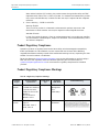
Documentation Conventions
This guide may use some special symbols and fonts to call your attention to important information. The following symbols appear throughout this guide:
DANGER: The Danger symbol calls your attention to information that, if ignored, can cause physical harm to
you.
CAUTION: The Caution symbol calls your attention to information that, if ignored, can adversely affect
the performance of your Harmonic product, or that can make a procedure needlessly difficult.
LASER DANGER: The Laser symbol and the Danger alert call your attention to information about the lasers
in this product that, if ignored, can cause physical harm to you.
NOTE: The Note symbol calls your attention to additional information that you will benefit from heeding. It
may be used to call attention to an especially important piece of information you need, or it may provide
additional information that applies in only some carefully delineated circumstances.
IMPORTANT: The Important symbol calls your attention to information that should stand out when you are
reading product details and procedural information.
TIP: The Tip symbol calls your attention to parenthetical information that is not necessary for performing a
given procedure, but which, if followed, might make the procedure or its subsequent steps easier, smoother, or
more efficient.
In addition to these symbols, this guide may use the following text conventions:
Convention Explanation
Typed Command Indicates the text that you type in at the keyboard
prompt.
<Ctrl>, <Ctrl>+<Shift> A key or key sequence to press.
Links The italics in blue text to indicate Cross-references, and
hyperlinked cross-references in online documents.
Bold Indicates a button to click, or a menu item to select.
ScreenOutput The text that is displayed on a computer screen.
Emphasis The italics text used for emphasis and document
references.
NOTE: You require Adobe Reader or Adobe Acrobat version 6.0 or later to open the PDF files. You can
download Adobe Reader free of charge from www.adobe.com.

Table of Contents
© 2015 Harmonic Inc. All rights reserved. 5 ProStream 1000 Release 6.8, Rev A
Table of Contents
Chapter 1: ProStream 1000 Overview........................................................... 8
Control Modes . . . . . . . . . . . . . . . . . . . . . . . . . . . . . . . . . . . . . . . . . . . . . . . . . . . . . . . . . . . . . . .8
System Requirements of Managing PC . . . . . . . . . . . . . . . . . . . . . . . . . . . . . . . . . . . . . . . . .8
ProStream 1000 Device Features . . . . . . . . . . . . . . . . . . . . . . . . . . . . . . . . . . . . . . . . . . . . . . .8
ProStream 1000 Device Types . . . . . . . . . . . . . . . . . . . . . . . . . . . . . . . . . . . . . . . . . . . . . . .9
ProStream 1000 Front Panel. . . . . . . . . . . . . . . . . . . . . . . . . . . . . . . . . . . . . . . . . . . . . . . . . . . .9
Front Bezel . . . . . . . . . . . . . . . . . . . . . . . . . . . . . . . . . . . . . . . . . . . . . . . . . . . . . . . . . . . . . . . .9
Control Panel . . . . . . . . . . . . . . . . . . . . . . . . . . . . . . . . . . . . . . . . . . . . . . . . . . . . . . . . . . . . 10
Front Panel LEDs . . . . . . . . . . . . . . . . . . . . . . . . . . . . . . . . . . . . . . . . . . . . . . . . . . . . . . . . . 10
ProStream 1000 Back Panel . . . . . . . . . . . . . . . . . . . . . . . . . . . . . . . . . . . . . . . . . . . . . . . . . . 10
Power Supply . . . . . . . . . . . . . . . . . . . . . . . . . . . . . . . . . . . . . . . . . . . . . . . . . . . . . . . . . . . . 10
Central Processing Card (CPC) . . . . . . . . . . . . . . . . . . . . . . . . . . . . . . . . . . . . . . . . . . . . . . 11
IOM Slots and Cards . . . . . . . . . . . . . . . . . . . . . . . . . . . . . . . . . . . . . . . . . . . . . . . . . . . . . . 12
8VSB Modulation Card . . . . . . . . . . . . . . . . . . . . . . . . . . . . . . . . . . . . . . . . . . . . . . . . . . . . 16
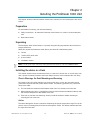
Chapter 2: Installing the ProStream 1000 Unit .........................................18
Preparation . . . . . . . . . . . . . . . . . . . . . . . . . . . . . . . . . . . . . . . . . . . . . . . . . . . . . . . . . . . . . . . . 18
Unpacking . . . . . . . . . . . . . . . . . . . . . . . . . . . . . . . . . . . . . . . . . . . . . . . . . . . . . . . . . . . . . . . . . 18
Installing the device in a Rack. . . . . . . . . . . . . . . . . . . . . . . . . . . . . . . . . . . . . . . . . . . . . . . . . 18
Chassis Warnings for Rack Mounting and Servicing . . . . . . . . . . . . . . . . . . . . . . . . . . . . 18
Mounting the device . . . . . . . . . . . . . . . . . . . . . . . . . . . . . . . . . . . . . . . . . . . . . . . . . . . . . . 19
Inserting the IOM Cards and RF Input Card. . . . . . . . . . . . . . . . . . . . . . . . . . . . . . . . . . . . . . 19
ESD Guidelines . . . . . . . . . . . . . . . . . . . . . . . . . . . . . . . . . . . . . . . . . . . . . . . . . . . . . . . . . . 19
Cabling the ProStream 1000 . . . . . . . . . . . . . . . . . . . . . . . . . . . . . . . . . . . . . . . . . . . . . . . . . 20
Connecting the Ethernet Cables . . . . . . . . . . . . . . . . . . . . . . . . . . . . . . . . . . . . . . . . . . . . 20
Connecting the ASI Input/Output Ports . . . . . . . . . . . . . . . . . . . . . . . . . . . . . . . . . . . . . . . 21
Connecting the GbE Input/Output Ports . . . . . . . . . . . . . . . . . . . . . . . . . . . . . . . . . . . . . . 21
Connecting the Input 8VSB Modulation Card . . . . . . . . . . . . . . . . . . . . . . . . . . . . . . . . . 22
Connecting Power . . . . . . . . . . . . . . . . . . . . . . . . . . . . . . . . . . . . . . . . . . . . . . . . . . . . . . . . 22
Inserting/Replacing IPC Cards. . . . . . . . . . . . . . . . . . . . . . . . . . . . . . . . . . . . . . . . . . . . . . . . . 23
Chapter 3: Initial Device Configuration ......................................................27
Initial Configuration in NMX control mode. . . . . . . . . . . . . . . . . . . . . . . . . . . . . . . . . . . . . . . 27
Start Using the Device — NMX Control Mode . . . . . . . . . . . . . . . . . . . . . . . . . . . . . . . . . 28
Initial Configuration in Standalone Control Mode . . . . . . . . . . . . . . . . . . . . . . . . . . . . . . . . . 28
Control Panel Overview . . . . . . . . . . . . . . . . . . . . . . . . . . . . . . . . . . . . . . . . . . . . . . . . . . . 28
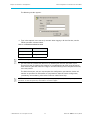
Setting Network Properties . . . . . . . . . . . . . . . . . . . . . . . . . . . . . . . . . . . . . . . . . . . . . . . . 30
Setting the IP Address of Management Port . . . . . . . . . . . . . . . . . . . . . . . . . . . . . . . . . . . 31
Setting the Subnet Mask . . . . . . . . . . . . . . . . . . . . . . . . . . . . . . . . . . . . . . . . . . . . . . . . . . . 31
Setting the Default Gateway Address . . . . . . . . . . . . . . . . . . . . . . . . . . . . . . . . . . . . . . . . 31
Viewing MAC Address . . . . . . . . . . . . . . . . . . . . . . . . . . . . . . . . . . . . . . . . . . . . . . . . . . . . 32
Starting to Use the Device - Standalone Control Mode . . . . . . . . . . . . . . . . . . . . . . . . . 32

Table of Contents
© 2015 Harmonic Inc. All rights reserved. 6 ProStream 1000 Release 6.8, Rev A
Logging into the Device . . . . . . . . . . . . . . . . . . . . . . . . . . . . . . . . . . . . . . . . . . . . . . . . . . . 32
Chapter 4: Upgrading Firmware...................................................................34
Upgrading Firmware in NMX Control Mode . . . . . . . . . . . . . . . . . . . . . . . . . . . . . . . . . . . . . 34
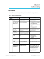
Chapter 5: Troubleshooting..........................................................................35
Troubleshooting . . . . . . . . . . . . . . . . . . . . . . . . . . . . . . . . . . . . . . . . . . . . . . . . . . . . . . . . . . . . 35
Chapter 6: Maintenance...............................................................................59
Air Filters . . . . . . . . . . . . . . . . . . . . . . . . . . . . . . . . . . . . . . . . . . . . . . . . . . . . . . . . . . . . . . . . . . 59
Maintaining the Filters . . . . . . . . . . . . . . . . . . . . . . . . . . . . . . . . . . . . . . . . . . . . . . . . . . . . . 59
Replacing the Bezel Filter . . . . . . . . . . . . . . . . . . . . . . . . . . . . . . . . . . . . . . . . . . . . . . . . . . 60
Replacing the Keypad Filter . . . . . . . . . . . . . . . . . . . . . . . . . . . . . . . . . . . . . . . . . . . . . . . . 60
Fan Replacement . . . . . . . . . . . . . . . . . . . . . . . . . . . . . . . . . . . . . . . . . . . . . . . . . . . . . . . . . . . 60
Removing and Replacing the Fans . . . . . . . . . . . . . . . . . . . . . . . . . . . . . . . . . . . . . . . . . . 61
Fuse Replacement . . . . . . . . . . . . . . . . . . . . . . . . . . . . . . . . . . . . . . . . . . . . . . . . . . . . . . . . . . 62
Replacing the fuse . . . . . . . . . . . . . . . . . . . . . . . . . . . . . . . . . . . . . . . . . . . . . . . . . . . . . . . . 62
Appendix A: Contacting the Technical Assistance Center .........................63
Appendix B: Safety and Regulatory Compliance Information...................65
Important Safety Instructions . . . . . . . . . . . . . . . . . . . . . . . . . . . . . . . . . . . . . . . . . . . . . . . . . 65
Safety Symbols & Translated Safety, Warning & Caution Instructions (English) . . . . . . . . . 65
Symboles de sécurité et traduits de sécurité, d'avertissement et Attention Instructions
(français) . . . . . . . . . . . . . . . . . . . . . . . . . . . . . . . . . . . . . . . . . . . . . . . . . . . . . . . . . . . . . . . . . . 68
Sicherheit Symbole und übersetzt Sicherheit, Achtung & Vorsicht Anleitung (Deutsch) . 71
Site Preparation Instructions . . . . . . . . . . . . . . . . . . . . . . . . . . . . . . . . . . . . . . . . . . . . . . . . . . 74
Product End-of-Life Disassembly Instructions . . . . . . . . . . . . . . . . . . . . . . . . . . . . . . . . . . . 76
Product Disassembly Process . . . . . . . . . . . . . . . . . . . . . . . . . . . . . . . . . . . . . . . . . . . . . . 76
Safety Rules (English) . . . . . . . . . . . . . . . . . . . . . . . . . . . . . . . . . . . . . . . . . . . . . . . . . . . . . 76
Règles de sécurité (French) . . . . . . . . . . . . . . . . . . . . . . . . . . . . . . . . . . . . . . . . . . . . . . . . 76
EU Manufacturer’s Declaration of Conformity . . . . . . . . . . . . . . . . . . . . . . . . . . . . . . . . . . . 77
Electromagnetic Compatibility Notices – Class A . . . . . . . . . . . . . . . . . . . . . . . . . . . . . . . . 77
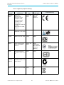
Product Regulatory Compliance . . . . . . . . . . . . . . . . . . . . . . . . . . . . . . . . . . . . . . . . . . . . . . 79
Product Regulatory Compliance Markings . . . . . . . . . . . . . . . . . . . . . . . . . . . . . . . . . . . . . . 79
Product Environmental Compliance . . . . . . . . . . . . . . . . . . . . . . . . . . . . . . . . . . . . . . . . . . . 81
EU RoHS . . . . . . . . . . . . . . . . . . . . . . . . . . . . . . . . . . . . . . . . . . . . . . . . . . . . . . . . . . . . . . . . 81
EU REACH . . . . . . . . . . . . . . . . . . . . . . . . . . . . . . . . . . . . . . . . . . . . . . . . . . . . . . . . . . . . . . 82
China RoHS . . . . . . . . . . . . . . . . . . . . . . . . . . . . . . . . . . . . . . . . . . . . . . . . . . . . . . . . . . . . . 82
Other RoHS and REACH type Regulations . . . . . . . . . . . . . . . . . . . . . . . . . . . . . . . . . . . . 84
Waste Electrical and Electronic Equipment (WEEE) . . . . . . . . . . . . . . . . . . . . . . . . . . . . . 84
Battery Directive . . . . . . . . . . . . . . . . . . . . . . . . . . . . . . . . . . . . . . . . . . . . . . . . . . . . . . . . . 84
WEEE Take-Back Request Program . . . . . . . . . . . . . . . . . . . . . . . . . . . . . . . . . . . . . . . . . . 84
Compliance with additional country specific environmental, safety and EMC standards: 85
Appendix C: Physical Specifications ............................................................86

Table of Contents
© 2015 Harmonic Inc. All rights reserved. 7 ProStream 1000 Release 6.8, Rev A
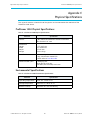
ProStream 1000 Physical Specifications . . . . . . . . . . . . . . . . . . . . . . . . . . . . . . . . . . . . . . . . 86
Environmental Specifications . . . . . . . . . . . . . . . . . . . . . . . . . . . . . . . . . . . . . . . . . . . . . . . . . 86
Appendix D: Control Panel Messages ..........................................................87
Control Panel Messages . . . . . . . . . . . . . . . . . . . . . . . . . . . . . . . . . . . . . . . . . . . . . . . . . . . . . 87
Successful Boot . . . . . . . . . . . . . . . . . . . . . . . . . . . . . . . . . . . . . . . . . . . . . . . . . . . . . . . . . . 87
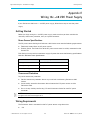
Appendix E: Wiring the –48 VDC Power Supply........................................89
Getting Started . . . . . . . . . . . . . . . . . . . . . . . . . . . . . . . . . . . . . . . . . . . . . . . . . . . . . . . . . . . . . 89
Power Source Specifications . . . . . . . . . . . . . . . . . . . . . . . . . . . . . . . . . . . . . . . . . . . . . . . 89
Overcurrent Protection . . . . . . . . . . . . . . . . . . . . . . . . . . . . . . . . . . . . . . . . . . . . . . . . . . . . 89
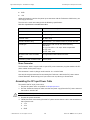
Wiring Requirements . . . . . . . . . . . . . . . . . . . . . . . . . . . . . . . . . . . . . . . . . . . . . . . . . . . . . . . . 89
Power Connector . . . . . . . . . . . . . . . . . . . . . . . . . . . . . . . . . . . . . . . . . . . . . . . . . . . . . . . . 90
Assembling the DC Input Power Cable . . . . . . . . . . . . . . . . . . . . . . . . . . . . . . . . . . . . . . . . . 90
Connecting the Power Cable to the ProStream 1000 . . . . . . . . . . . . . . . . . . . . . . . . . . . . . 91

© 2015 Harmonic Inc. All rights reserved. ProStream 1000 Release 6.8, Rev A
Chapter 1
ProStream 1000 Overview
ProStream 1000 is a digital video multiplexer/scrambler that suits the dynamic requirements of
various market segments such as Telco, Cable, DBS and Broadcast. ProStream 1000 receives
MPEG streams over Gigabit Ethernet (GbE) and/or DVB-ASI inputs. It multiplexes, scrambles and
outputs the content over GbE and/or DVB-ASI ports. The number of input and output ports
changes according to device configuration to fully meet customer’s needs.
Control Modes
ProStream 1000supports the following control mode options:
NMX - Harmonic's NMX Digital Service Manager offers comprehensive management of
networks including automatic device redundancy, source switching and automation.
ProStream 1000 is managed as an integral part of a broadcasting system.
NOTE: The current ProStream 1000 version is NMX controlled only.
Stand-alone - the device is managed as a stand-alone device independent of the
broadcasting system. It is controlled by a Web client which is an on-board interface
accessible through Microsoft Internet Explorer with comprehensive management capabilities.
NOTE: Some features, like scrambling and device redundancy are supported in NMX control mode only.
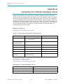
System Requirements of Managing PC
System requirements of the managing computer vary according to the control mode as the
following table lists:
Table 1–1: Control Mode Requirements
Control Mode Requirements
NMX NMX runs on an NMX computer which is a Harmonic approved DellTM
Computer.
Standalone
Pentuim 3.x or higher
Windows 2000, XP
Internet Explorer 5.0 - 6.0
ProStream 1000 Device Features
The main features and capabilities of the device are as follows:
Modular platform - provides a density of up to 5 IOM (Input Output Module) cards in a single
one-rack-unit (1-RU) chassis. The modular design allows a flexible and easy field replacement
of cards as well as field upgrades of SW and HW features.
IP IOM card - when mounted in the device, ProStream 1000 receives and transmits data via a
GbE port. Each IP IOM card has two active GbE ports.

Chapter 1 ProStream 1000 Overview
© 2015 Harmonic Inc. All rights reserved. 9 ProStream 1000 Release 6.8, Rev A
ProStream 1000 Front Panel
DVB-ASI IOM card - when mounted in the device, ProStream 1000 receives and transmits
data via four DVB-ASI ports. Each port may be configured as an input or output port. The
following two types of DVB-ASI cards are available:
ASI-RMX – allows the ProStream 1000 to receive and transmit data and streams and to
re-multiplex them according to user’s needs. The ASI-RMX card supports maximum bit
rate of 140 Mbps.
ASI-SCR – in addition to the ASI-RMX capabilities, this card type also supports DVB-CSA
(Common Scrambling Algorithm). The ASI-SCR card supports maximum bit rate of 140
Mbps.
NOTE: For further details, see DVB-ASI IOM Card.
Input Extraction capability - the device extracts incoming feeds and displays their structure
and elements on the control interface in a user friendly view.
Full multiplexing capability — content may be routed from any input port to any output port.
Advanced scrambling - the ProStream 1000 scrambles the input content in compliance with
the DVB-CSA standard. This feature is available for both GbE and DVB-ASI output ports, in
NMX control mode.
ProStream 1000 Device Types
Harmonic ProStream 1000 device is available with two types of chassis:
A chassis with a removable front panel - Chassis part number PRM-1K-CHS-AC-L
A chassis with a fixed front panel - Chassis part number PRM-1K-CHS-AC-B-L
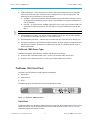
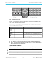
ProStream 1000 Front Panel
The front panel of ProStream 1000 contains the following:
Front bezel
Control Panel
LEDs
The following figure illustrates the front panel of ProStream 1000:
POWER
FAULT
LOCAL
ACTIVITY
Figure 1–1: ProStream 1000 Front Panel
Front Bezel
ProStream 1000 has a detachable front bezel that snaps on top of the control panel. The air inlets
located on the left side of the bezel provide access to the reusable air filters. See Air Filters for
information about cleaning the air filters.

Chapter 1 ProStream 1000 Overview
© 2015 Harmonic Inc. All rights reserved. 10 ProStream 1000 Release 6.8, Rev A
ProStream 1000 Back Panel
Control Panel
The control panel consists of an LCD display and a keypad. The control panel enables preliminary
configuration and basic monitoring of ProStream 1000. It is usually used for standalone devices.
For further information, see Initial Device Configuration.
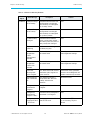
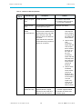
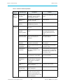
Front Panel LEDs
The four LEDs on the front panel indicate the operational status. The LEDs function the same
whether ProStream 1000 is operating in standalone or NMX control mode.The following table
describes the front panel LEDs, from top to bottom.
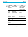
Table 1–2: Front Panel LEDs
LED Color Description
Power Green
Orange
Device is on and boot up process is complete.
Device is on and boot up process is taking place.
Fault Red An alarm has been activated in the device. Refer to Troubleshooting
for further details.***
Local Orange Identify the device, indicates the device when it needs service.
Activity Currently not applicable
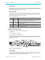
ProStream 1000 Back Panel
The back panel of ProStream 1000 contains the following:
Power Plug
Central Processing Card (CPC)
Input/Output Module (IOM) card Slots
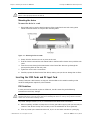
The following figure illustrates the back panel of the ProStream 1000 device with an optional
configuration of the IOM cards. The number and type of mounted IOM cards may vary according
to the needs of the user:
Figure 1–2: ProStream 1000 Back Panel
Power Supply
ProStream 1000 supports both VAC and VDC according to your requirements. A fuse is located
inside the power socket. For information about replacing the fuse, see Fuse Replacement. The
compartment next to the power cable holds a spare fuse.

Chapter 1 ProStream 1000 Overview
© 2015 Harmonic Inc. All rights reserved. 11 ProStream 1000 Release 6.8, Rev A
ProStream 1000 Back Panel
VAC Power Supply
The power supply supports 85-264 VAC range. The required voltage is automatically selected
according to the wall outlet.
The following table lists the power supply specifications.
Table 1–3: VAC Power Supply Specifications
Parameter Specification
Input voltage 85 - 264 VAC (autoselected)
Line frequency 47 - 63 Hz
Typical power consumption 125 W
-48 VDC Power Supply
The -48 VDC power supply unit is supplied with the required 3-pin male connector. See Appendix
E, Wiring the –48 VDC Power Supply for instructions to connect the power supply.
The ProStream 1000’s electrical rating for the -48VDC version is as follows:
Table 1–4: -48VDC Power Supply
Parameter Specification
Voltage 36 - 72VDC
Maximum Operating Current 4A
Each power supply unit features two LEDs. For detailed description, see VAC Power Supply.
NOTE: Consideration should be given to the connection of the equipment to the supply circuit and the
effect that overloading of circuits might have on overcurrent protection and supply wiring. Appropriate
consideration of equipment nameplate ratings should be used when addressing this concern.
Central Processing Card (CPC)
The Central Processing Card (CPC) is the main card of the ProStream 1000 platform. It includes
the communication interfaces of the device and additional components all of which are described
henceforth:
Three Ethernet ports - the Ethernet ports allow connection to separate networks. The
Ethernet ports are labeled ETH1-3. ETH3 port is used to connect the device to the
management network and ETH2 port for CAS network when required. ETH1 is optional for
future use.
ETH1 is 10/100 Base-T port and ETH 2 and 3 are 10/100/1000 Base-T ports. For cabling
instructions, see Installing the ProStream 1000 Unit.
EIA-RS-232 Serial Communication Port - the EIA-RS-232 serial port is used for technical
support only.
Status LEDs - currently not in use.
Fault Relay Port - currently not in use.

Chapter 1 ProStream 1000 Overview
© 2015 Harmonic Inc. All rights reserved. 12 ProStream 1000 Release 6.8, Rev A
ProStream 1000 Back Panel
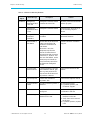
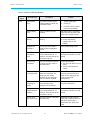
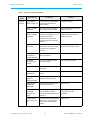
CPC LEDs - the following table lists the CPC LEDs from top to bottom and explains their
functionality. The LEDs function similar whether ProStream 1000 operates in standalone or
NMX control mode:
Table 1–5: CPC LEDs
LED Color Explanation
Fault Red Same as front panel. An alarm has been issued. For further details, refer
to Troubleshooting.
Locator Blue Identify unit, indicates the device when it needs service.
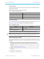
IOM Slots and Cards
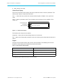
The ProStream 1000 device back panel has five Input Output Module (IOM) slots labeled one to
five. Each one of the slots accommodates a single IOM card. The following figure illustrates the
arrangement of the slots at the back panel:
Figure 1–3: ProStream 1000 Slot Arrangement
ProStream 1000 Version 5.0 & Up supports two types of DVB-ASI card and GbE IOM card. The
part numbers of the IOM cards as follows:
DVB-ASI RMX-IOM card - PRM-1K-ASI-RMX-0001-L
DVB-ASI SCR-IOM card - PRM-1K-ASI-SCR-0001-L
GbE IOM card - PRM-1K-IOM-GBE-0002-L
8VSB Modulation card - PRM-1K-IOM-8VSB
DVB-ASI IOM Card
NOTE: The following information applies to both types of the DVB-ASI card.
Each DVB-ASI IOM card has four independent ports labeled ASI 1- 4. Each port may be
configured as an input or output port. The following table lists the ASI card specifications:
Table 1–6: ASI Card Specifications
Feature Description
Number of Ports 4 x ASI ports. Each port may be configured as an input or output
port.
In DVB-ASI-SCR card, port two may be configured to receive the
GPS frequency.

Chapter 1 ProStream 1000 Overview
© 2015 Harmonic Inc. All rights reserved. 13 ProStream 1000 Release 6.8, Rev A
ProStream 1000 Back Panel
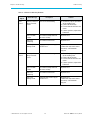
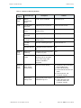
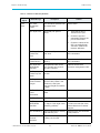
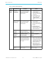
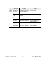
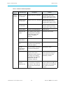
ASI Port LEDs
Each ASI port features two LEDs: Tx and Rx. The following table describes the available status of
each LED:
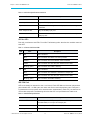
Table 1–7: Status of ASI Port LEDs
LED Color Description
Rx Off Port is disabled
Red Port is enabled and there is no ASI input flow
Amber Port is enabled and invalid MPEG data is detected
Green Port is enabled and nulls only are detected in the flow
Blinking green Port is enabled and traffic is flowing
Tx Off Port is disabled
Red Port is enabled and overflow is detected in output port
Green Port is enabled and nulls only are detected in the flow
Blinking green Port is enables and traffic is flowing
GbE IOM Card
GbE cards should be mounted in slots 1 and 2 only. Each GbE IOM card has two independent
ports labeled GbE 1-2. Both ports are active and work as two independent ports. Each port is
bi-directional and may receive and transmit streams simultaneously. Each GbE port includes an
SFP module receptacle. The following table lists the GbE card specifications of both cards:
Connector Female BNC connector
Max. input bit rate Up to 156 Mbps per port
Input extraction Extraction of incoming streams is displayed on the management
interface.
Max. output bit rate Up to 140 Mbps per port
Multicast content Content elements may be simultaneously routed to multiple
output ports.
Table 1–8: GbE Card Specifications
Feature Description
Number of Ports Two independent GbE ports per IOM card. Each port serves
simultaneously as an input and output port.
Connector Two receptacles for SFP module
Max. input bit rate Up to 400 Mbps per card
Table 1–6: ASI Card Specifications
continued
Feature Description

Chapter 1 ProStream 1000 Overview
© 2015 Harmonic Inc. All rights reserved. 14 ProStream 1000 Release 6.8, Rev A
ProStream 1000 Back Panel
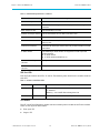
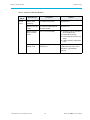
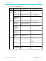
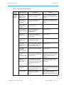
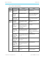
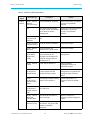
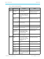
GbE Port LEDs
Each GbE port features two LEDs: Tx and Rx. The following table describes the available status of
each LED:
Table 1–9: Status of GbE Port LEDs
LED Status Color Description
Activity Green On - A live fiber is connected to the port and a network link
is detected.
Blinking - A real traffic flows through the link.
Alarm Red On - Indicates an error in the GbE port.
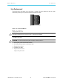
SFP Module
The SFP (Small Form Pluggable) module converts incoming data to match the GbE card interface.
There are two types of SFP modules:
Fiber optic SFP
Copper SFP
Number of input sockets Up to 128 sockets SPTS or MPTS for both cards
Input extraction Extraction of incoming streams is displayed on the management
interface.
Max. output bit rate Up to 400 Mbps per card
Number of output sockets Up to 128 sockets SPTS or MPTS for both cards
Input Dejitering capability Up to 50msc point-to-point
Multicast content Content elements may be simultaneously routed to multiple
output ports.
Null Packet Insertion Constant Bit rate output stream with null packet insertion and PCR
correction.
IP UDP modes The following IP UDP modes are supported in both input and
output streams:
IP UDP unicast
IP UDP multicast (IGMP Ver. 2)
Max. number of input
services
512 per device
Max. number of output
services
512 per device
Table 1–8: GbE Card Specifications
continued
Feature Description

Chapter 1 ProStream 1000 Overview
© 2015 Harmonic Inc. All rights reserved. 15 ProStream 1000 Release 6.8, Rev A
ProStream 1000 Back Panel
The following figure illustrates both types of the SFP module)
Copper SFP
Fiber SFP
Figure 1–4: SFP Types
LASER DANGER: Class I laser product.
You can use either of the types of SFP depending on the cable/fiber type you are using. You can
purchase SFPs from Harmonic or other sources. In this case, it is strongly recommended to
purchase SFP models qualified by Harmonic:
Table 1–10: SFP Types
Fiber/Cable Type Connector
Type Wave Length Qualified SFP Make/
Model Harmonic Part
Num.
Multimode fiber 2 x LC 850 nm Finisar FTRJ-8519-7D SFP-850
Singlemode fiber 2 x LC
1310 nm
1550 nm
Finisar FTRJ-1310-3
Finisar FTRJ-1550-7D
SFP-1310
SFP-1550
Shielded and
grounded CAT-6
or CAT-7
1 x RJ-45 N/A Finisar FCMJ-8521-
3(HR)
GSF9100-02-1
An optical SFP has two LC sockets, Receive (Rx) and Transmit (Tx). Use Multimode or Singlemode
fiber optics to connect your Gigabit Ethernet switch to the Rx socket. If bi-directional topology is
used, connect the Tx socket back to the switch. The following table lists the fibers and SFPs
required accordingly:
Table 1–11: Fiber and Required SFP
Fiber SFP
Multimode 850 nm SFP
Singlemode
1310 nm SFP for transferring signals to a distance of up to 1 km.
1550 nm SFP for transferring signals to a distance of up to 100 km
(depending on other network parameters).

Chapter 1 ProStream 1000 Overview
© 2015 Harmonic Inc. All rights reserved. 16 ProStream 1000 Release 6.8, Rev A
ProStream 1000 Back Panel
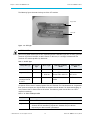
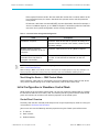
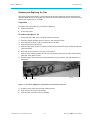
8VSB Modulation Card
The 8VSB modulation card is an RF input module that enables the reception of ATSC terrestrial
TV. It receives four independent ATSC 8VSB signals on the inputs and outputs four MPEG-2
Transport Streams.
NOTE: The four inputs are enabled by optional firmware licenses.
8VSB Modulation Card Specifications
Table 1–12 provides the specifications for the RF module.
Table 1–12: RF Module Specifications
Feature Support
Connectors 4x Type F, 75 per IEC 60169-24
Modulation 8–VSB (ATSC compliant)
Tuning Range VHF/UHF (Channels 2–59)
Note: The tuning range is limited to Channels 2 to 59 by
software (and SCTE 02-2006), per the FCC/Industry
Canada decisions to release channels 60 to 69 for public
safety use.
Sensitivity –83dBm/6 MHz
Dynamic Range > 80dB
MPEG Format 188 Bytes per TS packet
MPEG-2 TS MPTS and SPTS
Environmental and Physical
Compliant with ROHS Directive 2002/95/EC. Refer to the encoder environmental specifications
for additional information.
Figure 1–5 displays the module (rear panel).
Figure 1–5: RF Input Module

Chapter 1 ProStream 1000 Overview
© 2015 Harmonic Inc. All rights reserved. 17 ProStream 1000 Release 6.8, Rev A
ProStream 1000 Back Panel
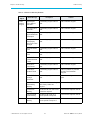
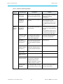
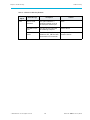
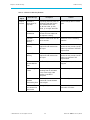
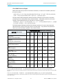
RF Module LED Lights
The LED lights show status, as shown in Table 1–13.
Table 1–13: LED Status Lights
Display Status
Off Port disabled
Blinking Yellow Loss of sync
Red Packet error rate (PER) threshold exceeded
Steady yellow SNR below threshold
Green Port Enabled, no alarms

© 2015 Harmonic Inc. All rights reserved. 18 ProStream 1000 Release 6.8, Rev A
Chapter 2
Installing the ProStream 1000 Unit
This chapter describes how to install the device into a standard EIA 19-inch computer rack and to
cable it.
Preparation
For installation and cabling, you need the following
Phillips screwdriver - to mount the ProStream 1000 device in a standard 19-inch computer
rack.
Rack-mount screws.
Unpacking
The ProStream 1000 device comes in a specially designed shipping container that ensures the
integrity of the unit.
When you unpack the ProStream 1000 device, you should find the following items:
Device.
Standard IEC power cord.
Spare air filters.
Installation manual.
NOTE: The AC power input cable shall comply with national electrical code and 18 AWG minimum.
Installing the device in a Rack
This section describes how to mount the device in a standard 19-inch rack. A 30 inch deep rack
with a spacer or chimney between racks with multiple devices is the recommended rack setup.
Chassis Warnings for Rack Mounting and Servicing
To prevent bodily injury when mounting or servicing this unit in a rack, you must take special
precautions to ensure that the system remains stable. The following guidelines are provided to
assure your safety:
This unit should be mounted at the bottom of the rack if it is the only unit in the rack.
When mounting this unit in a partially filled rack, load the rack from the bottom to the top with
the heaviest component at the bottom of the rack.
If the rack is provided with stabilizing devices, install the stabilizers before mounting or
servicing the unit in the rack.
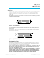
Airflow
The airflow through the device is critical for maintaining the proper temperature range. Fans in the
chassis draw air in through the front bezel and through the device. The airflow ventilates out from
the right side (front view).

Chapter 2 Installing the ProStream 1000 Unit
© 2015 Harmonic Inc. All rights reserved. 19 ProStream 1000 Release 6.8, Rev A
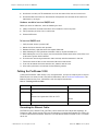
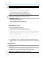
Inserting the IOM Cards and RF Input Card
CAUTION: Do not obstruct the airflow of the device. Severe equipment damage can result when the
device cannot properly exhaust the airflow.
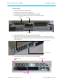
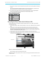
Mounting the device
To mount the device in a rack
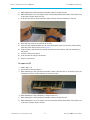
1. Using both hands, grasp the outside corners of the plastic front bezel and slowly pull to
detach it from the device and expose the mounting holes.
Figure 2–1: Mounting ProStream 1000
2. Gently slide the device to rest in its place on the rack.
3. Push the device back until the rack-mount holes in the front of the device line up with the rack
posts.
4. Insert four screws through the mount holes in the front of the device to go through the
corresponding holes on the rack posts.
5. Tighten the screws with a screwdriver.
6. Carefully replace the front bezel of the device, making sure you do not damage the air filters.
Inserting the IOM Cards and RF Input Card
Usually, ProStream 1000 devices are shipped with the IOM cards installed according to the
hardware configuration required by the customer.
ESD Guidelines
In case you need to install or replace an IOM card, handle it according to the following
instructions to avoid any damage.
CAUTION: Electrostatic Discharge (ESD) may damage the device components. Take precautions to
eliminate ESD from your body and clothes before handling the device or card by using a wrist band and a
rubber mat and read the following section.
To prevent damage caused by ESD, it is recommended to follow these instructions:
When unpacking an IOM card, keep the card in the anti-static wrapping until you are ready to
install it in the device. Unwrap the card only at an ESD workstation or when grounded.
If for any reason you cannot insert the card, lay it in an anti-static container or packaging.

Chapter 2 Installing the ProStream 1000 Unit
© 2015 Harmonic Inc. All rights reserved. 20 ProStream 1000 Release 6.8, Rev A
Cabling the ProStream 1000
Handle the card only at ESD workstation and use anti-static rubber mat and wrist bands.
Handle the IOM card with care. Do not touch components and contacts on the board and
hold board by its edges.
Hardware needed to insert an IOM/RF card
Before you insert an IOM card, have the following on hand:
Phillips screwdriver to remove the fillers and to fasten the card to its place.
ESD-preventing wrist band and a rubber mat
Powered off device.
To insert an IOM/RF card
1. Verify that the device is powered off.
2. Mount the device into the rack (optional)
3. Remove the filler panel that covers the required IOM slot.
4. While following the ESD guidelines mentioned above, unpack the IOM card.
5. While holding the card by its edges, insert it into the slot. Make sure that the sides of the card
slide into the guides of the IOM slot.
6. Push the card until its edge-connector mates securely with the connector in the slot.
7. Fasten the screws of the card to secure the IOM card to the chassis.
8. If you did not mount the device into the rack, mount it into the rack.
9. Start cabling the device as instructed in the following section.
Cabling the ProStream 1000
Cabling the ProStream 1000 device is very straight forward. All input and output ports as well as
Ethernet ports are clearly marked. For further information, refer to ProStream 1000 Back Panel. The
following table lists the ports, cables/fibers and the required connectors:
Table 2–1: Cabling ProStream 1000
Port Description Connector
ASI 75 Ohm coax cables Standard BNC
GbE Multimode or singlemode optic fiber
or
Shielded and grounded CAT-6 or CAT-7
LC
RJ-45
Ethernet Shielded and grounded CAT-5E RJ-45
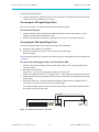
Connecting the Ethernet Cables
The Ethernet ports, labeled ETH2 and ETH3 provide access to two independent networks. All
ProStream 1000 devices use the ETH3 port to connect to a management network. The ETH2 port
is used to connect the ProStream 1000 to a CAS (Conditional Access) network. ETH1 is currently
not in use.
La page est en cours de chargement...
La page est en cours de chargement...
La page est en cours de chargement...
La page est en cours de chargement...
La page est en cours de chargement...
La page est en cours de chargement...
La page est en cours de chargement...
La page est en cours de chargement...
La page est en cours de chargement...
La page est en cours de chargement...
La page est en cours de chargement...
La page est en cours de chargement...
La page est en cours de chargement...
La page est en cours de chargement...
La page est en cours de chargement...
La page est en cours de chargement...
La page est en cours de chargement...
La page est en cours de chargement...
La page est en cours de chargement...
La page est en cours de chargement...
La page est en cours de chargement...
La page est en cours de chargement...
La page est en cours de chargement...
La page est en cours de chargement...
La page est en cours de chargement...
La page est en cours de chargement...
La page est en cours de chargement...
La page est en cours de chargement...
La page est en cours de chargement...
La page est en cours de chargement...
La page est en cours de chargement...
La page est en cours de chargement...
La page est en cours de chargement...
La page est en cours de chargement...
La page est en cours de chargement...
La page est en cours de chargement...
La page est en cours de chargement...
La page est en cours de chargement...
La page est en cours de chargement...
La page est en cours de chargement...
La page est en cours de chargement...
La page est en cours de chargement...
La page est en cours de chargement...
La page est en cours de chargement...
La page est en cours de chargement...
La page est en cours de chargement...
La page est en cours de chargement...
La page est en cours de chargement...
La page est en cours de chargement...
La page est en cours de chargement...
La page est en cours de chargement...
La page est en cours de chargement...
La page est en cours de chargement...
La page est en cours de chargement...
La page est en cours de chargement...
La page est en cours de chargement...
La page est en cours de chargement...
La page est en cours de chargement...
La page est en cours de chargement...
La page est en cours de chargement...
La page est en cours de chargement...
La page est en cours de chargement...
La page est en cours de chargement...
La page est en cours de chargement...
La page est en cours de chargement...
La page est en cours de chargement...
La page est en cours de chargement...
La page est en cours de chargement...
La page est en cours de chargement...
La page est en cours de chargement...
La page est en cours de chargement...
La page est en cours de chargement...
-
 1
1
-
 2
2
-
 3
3
-
 4
4
-
 5
5
-
 6
6
-
 7
7
-
 8
8
-
 9
9
-
 10
10
-
 11
11
-
 12
12
-
 13
13
-
 14
14
-
 15
15
-
 16
16
-
 17
17
-
 18
18
-
 19
19
-
 20
20
-
 21
21
-
 22
22
-
 23
23
-
 24
24
-
 25
25
-
 26
26
-
 27
27
-
 28
28
-
 29
29
-
 30
30
-
 31
31
-
 32
32
-
 33
33
-
 34
34
-
 35
35
-
 36
36
-
 37
37
-
 38
38
-
 39
39
-
 40
40
-
 41
41
-
 42
42
-
 43
43
-
 44
44
-
 45
45
-
 46
46
-
 47
47
-
 48
48
-
 49
49
-
 50
50
-
 51
51
-
 52
52
-
 53
53
-
 54
54
-
 55
55
-
 56
56
-
 57
57
-
 58
58
-
 59
59
-
 60
60
-
 61
61
-
 62
62
-
 63
63
-
 64
64
-
 65
65
-
 66
66
-
 67
67
-
 68
68
-
 69
69
-
 70
70
-
 71
71
-
 72
72
-
 73
73
-
 74
74
-
 75
75
-
 76
76
-
 77
77
-
 78
78
-
 79
79
-
 80
80
-
 81
81
-
 82
82
-
 83
83
-
 84
84
-
 85
85
-
 86
86
-
 87
87
-
 88
88
-
 89
89
-
 90
90
-
 91
91
-
 92
92


Harmonic ProStream 1000 6.8 Guide d'installation
- Taper
- Guide d'installation
dans d''autres langues
Documents connexes
-
Harmonic ProStream 1000 7.6 Guide d'installation
-
-
-
-
-
-
-
-
-
Autres documents
-
Sony STR-DN1050 Guide de référence
-
Watchguard AP327X Hardware Guide
-
Sony STR-DN860 Guide de référence
-
 Thompson ViBE EM4000 Manuel utilisateur
-
Oracle SPARC T7-4 Guide d'installation
-
Yamaha CD-S2000 Le manuel du propriétaire
-
Mitsubishi Electric MI1002-W Manuel utilisateur
-
3com SuperStack 3 3C16468 Manuel utilisateur
-
Yamaha NP-S2000 Le manuel du propriétaire
-
Sony HTS200F Manuel utilisateur
