Skil TS6307-00 Le manuel du propriétaire
- Catégorie
- Outils électroportatifs
- Taper
- Le manuel du propriétaire

WARNING: To reduce the risk of injury, the user must read and understand the
Owner’s Manual before using this product. Save these instructions for future reference.
AVERTISSEMENT : Afin de réduire les risques de blessure, l’utilisateur doit lire et
comprendre le guide d’utilisation avant d’utiliser cet article. Conservez le présent guide
afin de pouvoir le consulter ultérieurement.
ADVERTENCIA : Para reducir el riesgo de lesiones, el usuario debe leer y comprender
el Manual del operador antes de utilizar este producto. Guarde estas instrucciones para
consultarlas en caso sea necesario.
Owner’s Manual
Guide d’utilisation
Manual del propietario
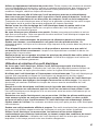
Table Saw
Scie à table
Sierra de mesa
For Customer Service
Pour le service à la clientèle
Servicio al cliente
1-877-SKIL-999
OR
www.skil.com
Model/ Modelo/ Modèle: TS6307-00
HEIGH T
+
2
0
15
30
45
22.5
BLADE ROTATION

2
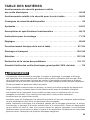
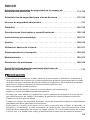
TABLE OF CONTENTS
General Power Tool Safety Warnings .............................3-4
Table Saw Safety Warnings .....................................4-8
Additional Safety Rules ..........................................8
Symbols ....................................................9-12
Functional Descriptions and Specications ...................... 13-15
Assembly Instructions .......................................15-24
Adjustments ................................................ 25-31
Basic Table Saw Operation ....................................32-46
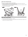
Storage and Transportation ...................................47-49
Maintenance ................................................ 50-52
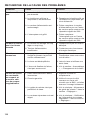
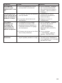
Troubleshooting ............................................52-53
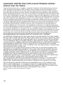
Limited Warranty of SKIL Consumer Bench Top Power Tools ..........54
WARNING
•
Some dust created by power sanding, sawing, grinding, drilling and other construction
activities contains chemicals known to the State of California to cause cancer, birth defects
or other reproductive harm. Some examples of these chemicals are:
–
Lead from lead-based paints.
–
Crystalline silica from bricks, cement, and other masonry products.
–
Arsenic and chromium from chemically-treated lumber.
•
Your risk from these exposures varies, depending upon how often you do this type of work.
To reduce your exposure to these chemicals:
–
Work in a well-ventilated area.
–
Work with approved safety equipment, such as dust masks that are specially designed to
lter out microscopic particles.
–
Avoid prolonged contact with dust from power sanding, sawing, grinding, drilling, and
other construction activities. Wear protective clothing and wash exposed areas with soap
and water. Allowing dust to get into your mouth or eyes or to lie on the skin may promote
absorption of harmful chemicals.

3
GENERAL POWER TOOL SAFETY WARNINGS
WARNING
Read all safety warnings, instructions, illustrations and specications
provided with this power tool.
Failure to follow all instructions listed
below may result in electric shock, re and/or serious injury.
SAVE ALL WARNINGS AND INSTRUCTIONS FOR FUTURE
REFERENCE.
The term “power tool” in the warnings refers to your mains-operated (corded) power tool or
battery-operated (cordless) power tool.
Work area safety
Keep work area clean and well lit
. Cluttered or dark areas invite accidents.
Do not operate power tools in explosive atmospheres, such as in the presence of
ammable liquids, gases or dust.
Power tools create sparks which may ignite the dust or
fumes.
Keep children and bystanders away while operating a power tool.
Distractions can cause
you to lose control.
Electrical safety
Power tool plugs must match the outlet. Never modify the plug in any way. Do not use
any adapter plugs with earthed (grounded) power tools.
Unmodied plugs and matching
outlets will reduce risk of electric shock.
Avoid body contact with earthed or grounded surfaces, such as pipes, radiators,
ranges and refrigerators.
There is an increased risk of electric shock if your body is earthed
or grounded.
Do not expose power tools to rain or wet conditions.
Water entering a power tool will
increase the risk of electric shock.
Do not abuse the cord. Never use the cord for carrying, pulling or unplugging the power
tool. Keep cord away from heat, oil, sharp edges or moving parts.
Damaged or entangled
cords increase the risk of electric shock.
When operating a power tool outdoors, use an extension cord suitable for outdoor use.
Use of a cord suitable for outdoor use reduces the risk of electric shock.
If operating a power tool in a damp location is unavoidable, use a ground fault circuit
interrupter (GFCI) protected supply.
Use of a GFCI reduces the risk of electric shock.
Personal safety
Stay alert, watch what you are doing and use common sense when operating a power
tool. Do not use a power tool while you are tired or under the inuence of drugs,
alcohol or medication.
A moment of inattention while operating power tools may result in
serious personal injury.
Use personal protective equipment. Always wear eye protection.
Protective equipment
such as a dust mask, non-skid safety shoes, hard hat or hearing protection used for
appropriate conditions will reduce personal injuries.
Prevent unintentional starting. Ensure the switch is in the off-position before
connecting to power source and/or battery pack, picking up or carrying the tool.
Carrying power tools with your nger on the switch or energising power tools that have the
switch on invites accidents.
Remove any adjusting key or wrench before turning the power tool on.
A wrench or a
key left attached to a rotating part of the power tool may result in personal injury.
Do not overreach. Keep proper footing and balance at all times.
This enables better
control of the power tool in unexpected situations.

4
Dress properly. Do not wear loose clothing or jewelry. Keep your hair and clothing
away from moving parts.
Loose clothes, jewelry or long hair can be caught in moving parts.
If devices are provided for the connection of dust extraction and collection facilities,
ensure these are connected and properly used.
Use of dust collection can reduce dust-
related hazards.
Do not let familiarity gained from frequent use of tools allow you to become complacent
and ignore tool safety principles.
A careless action can cause severe injury within a fraction
of a second.
Power tool use and care
Do not force the power tool. Use the correct power tool for your application.
The correct
power tool will do the job better and safer at the rate for which it was designed.
Do not use the power tool if the switch does not turn it on and off.
Any power tool that
cannot be controlled with the switch is dangerous and must be repaired.
Disconnect the plug from the power source and/or remove the battery pack, if
detachable, from the power tool before making any adjustments, changing accessories,
or storing power tools.
Such preventive safety measures reduce the risk of starting the
power tool accidentally.
Store idle power tools out of the reach of children and do not allow persons unfamiliar
with the power tool or these instructions to operate the power tool.
Power tools are
dangerous in the hands of untrained users.
Maintain power tools and accessories. Check for misalignment or binding of moving
parts, breakage of parts and any other condition that may affect the power tool’s
operation. If damaged, have the power tool repaired before use.
Many accidents are
caused by poorly maintained power tools.
Keep cutting tools sharp and clean.
Properly maintained cutting tools with sharp cutting
edges are less likely to bind and are easier to control.
Use the power tool, accessories and tool bits etc. in accordance with these instructions,
taking into account the working conditions and the work to be performed.
Use of the
power tool for operations different from those intended could result in a hazardous situation.
Keep handles and grasping surfaces dry, clean and free from oil and grease.
Slippery
handles and grasping surfaces do not allow for safe handling and control of the tool in
unexpected situations.
Service
Have your power tool serviced by a qualied repair person using only identical
replacement parts.
This will ensure that the safety of the power tool is maintained.
TABLE SAW SAFETY WARNINGS
Guarding related warnings
Keep guards in place. Guards must be in working order and be properly mounted.
A
guard that is loose, damaged, or is not functioning correctly must be repaired or replaced.
Always use saw blade guard, riving knife and anti-kickback device for every through-
cutting operation.
For through-cutting operations where the saw blade cuts completely
through the thickness of the workpiece, the guard and other safety devices help reduce the
risk of injury.
Immediately reattach the guarding system after completing an operation (such as
rabbeting, dadoing or resawing cuts) which requires removal of the guard, riving knife
and/or anti-kickback device.
The guard, riving knife, and anti-kickback device help to reduce
the risk of injury.

5
Make sure the saw blade is not contacting the guard, riving knife or the workpiece
before the switch is turned on.
Inadvertent contact of these items with the saw blade could
cause a hazardous condition.
Adjust the riving knife as described in this instruction manual.
Incorrect spacing,
positioning and alignment can make the riving knife ineffective in reducing the likelihood of
kickback.
For the riving knife and anti-kickback device to work, they must be engaged in the
workpiece.
The riving knife and anti-kickback device are ineffective when cutting workpieces
that are too short to be engaged with the riving knife and anti-kickback device. Under these
conditions a kickback cannot be prevented by the riving knife and antikickback device.
Use the appropriate saw blade for the riving knife.
For the riving knife to function properly,
the saw blade diameter must match the appropriate riving knife and the body of the saw blade
must be thinner than the thickness of the riving knife and the cutting width of the saw blade
must be wider than the thickness of the riving knife.
Cutting procedures warnings
DANGER
Never place your ngers or hands in the vicinity or in line with the saw
blade.
A moment of inattention or a slip could direct your hand towards the
saw blade and result in serious personal injury.
Feed the workpiece into the saw blade or cutter only against the direction of rotation.
Feeding the workpiece in the same direction that the saw blade is rotating above the table
may result in the workpiece, and your hand, being pulled into the saw blade.
Never use the miter gauge to feed the workpiece when ripping and do not use the rip
fence as a length stop when cross-cutting with the miter gauge.
Guiding the workpiece
with the rip fence and the miter gauge at the same time increases the likelihood of saw blade
binding and kickback.
When ripping, always apply the workpiece feeding force between the fence and the
saw blade. Use a push stick when the distance between the fence and the saw blade is
less than 150 mm, and use a push block when this distance is less than 50 mm.
“Work
helping” devices will keep your hand at a safe distance from the saw blade.
Use only the push stick provided by the manufacturer or constructed in accordance
with the instructions.
This push stick provides sufcient distance of the hand from the saw
blade.
Never use a damaged or cut push stick.
A damaged push stick may break causing your
hand to slip into the saw blade.
Do not perform any operation “freehand”. Always use either the rip fence or the miter
gauge to position and guide the workpiece.
”Freehand” means using your hands to
support or guide the workpiece, in lieu of a rip fence or miter gauge. Freehand sawing leads to
misalignment, binding and kickback.
Never reach around or over a rotating saw blade.
Reaching for a workpiece may lead to
accidental contact with the moving saw blade.
Provide auxiliary workpiece support to the rear and/or sides of the saw table for long
and/or wide workpieces to keep them level.
A long and/or wide workpiece has a tendency
to pivot on the table’s edge, causing loss of control, saw blade binding and kickback.
Feed workpiece at an even pace. Do not bend or twist the workpiece. If jamming occurs,
turn the tool off immediately, unplug the tool then clear the jam.
Jamming the saw blade
by the workpiece can cause kickback or stall the motor.
Do not remove pieces of cut-off material while the saw is running.
The material may
become trapped between the fence or inside the saw blade guard and the saw blade pulling
your ngers into the saw blade. Turn the saw off and wait until the saw blade stops before
removing material.

6
Use an auxiliary fence in contact with the tabletop when ripping workpieces less than
2 mm thick.
A thin workpiece may wedge under the rip fence and create a kickback.
Kickback causes and related warnings
Kickback is a sudden reaction of the workpiece due to a pinched, jammed saw blade or
misaligned line of cut in the workpiece with respect to the saw blade or when a part of the
workpiece binds between the saw blade and the rip fence or other xed object.
Most frequently during
kickback
, the workpiece is lifted from the table by the rear portion of
the saw blade and is propelled towards the operator.
Kickback is the result of saw misuse and/or incorrect operating procedures or conditions and
can be avoided by taking proper precautions as given below.
Never stand directly in line with the saw blade. Always position your body on the same
side of the saw blade as the fence.
Kickback may propel the workpiece at high velocity
towards anyone standing in front and in line with the saw blade.
Never reach over or in back of the saw blade to pull or to support the workpiece.
Accidental contact with the saw blade may occur or kickback may drag your ngers into the
saw blade.
Never hold and press the workpiece that is being cut off against the rotating saw blade.
Pressing the workpiece being cut off against the saw blade will create a binding condition and
kickback.
Align the fence to be parallel with the saw blade.
A misaligned fence will pinch the
workpiece against the saw blade and create kickback.
Use a featherboard to guide the workpiece against the table and fence when making
non-through cuts such as rabbeting, dadoing or resawing cuts.
A featherboard helps to
control the workpiece in the event of a kickback.
Use extra caution when making a cut into blind areas of assembled workpieces.
The
protruding saw blade may cut objects that can cause kickback.
Support large panels to minimise the risk of saw blade pinching and kickback.
Large
panels tend to sag under their own weight. Support(s) must be placed under all portions of the
panel overhanging the tabletop.
Use extra caution when cutting a workpiece that is twisted, knotted, warped or does not
have a straight edge to guide it with a miter gauge or along the fence.
A warped, knotted,
or twisted workpiece is unstable and causes misalignment of the kerf with the saw blade,
binding and kickback.
Never cut more than one workpiece, stacked vertically or horizontally.
The saw blade
could pick up one or more pieces and cause kickback.
When restarting the saw with the saw blade in the workpiece, centre the saw blade in
the kerf so that the saw teeth are not engaged in the material.
If the saw blade binds, it
may lift up the workpiece and cause kickback when the saw is restarted.
Keep saw blades clean, sharp, and with sufcient set. Never use warped saw blades
or saw blades with cracked or broken teeth.
Sharp and properly set saw blades minimise
binding, stalling and kickback.
Table saw operating procedure warnings
Turn off the table saw and disconnect the power cord when removing the table insert,
changing the saw blade or making adjustments to the riving knife, antikickback device
or saw blade guard, and when the machine is left unattended.
Precautionary measures
will avoid accidents.
Never leave the table saw running unattended. Turn it off and don’t leave the tool until it
comes to a complete stop.
An unattended running saw is an uncontrolled hazard.

7
Locate the table saw in a well-lit and level area where you can maintain good footing
and balance. It should be installed in an area that provides enough room to easily
handle the size of your workpiece.
Cramped, dark areas, and uneven slippery oors invite
accidents.
Frequently clean and remove sawdust from under the saw table and/or the dust
collection device.
Accumulated sawdust is combustible and may self-ignite.
The table saw must be secured.
A table saw that is not properly secured may move or tip
over.
Remove tools, wood scraps, etc. from the table before the table saw is turned on.
Distraction or a potential jam can be dangerous.
Always use saw blades with correct size and shape (diamond versus round) of arbour
holes.
Saw blades that do not match the mounting hardware of the saw will run off-centre,
causing loss of control.
Never use damaged or incorrect saw blade mounting means such as anges, saw blade
washers, bolts or nuts.
These mounting means were specially designed for your saw, for
safe operation and optimum performance.
Never stand on the table saw, do not use it as a stepping stool.
Serious injury could occur
if the tool is tipped or if the cutting tool is accidentally contacted.
Make sure that the saw blade is installed to rotate in the proper direction. Do not use
grinding wheels, wire brushes, or abrasive wheels on a table saw.
Improper saw blade
installation or use of accessories not recommended may cause serious injury.
Double Insulated Tools
Double insulation is a design concept used in electric power tools which eliminates the
need for the three wire grounded power cord and grounded power supply system. It is a
recognized and approved system by Underwriter’s Laboratories, CSA and Federal OSHA
authorities.
WARNING
Servicing of a tool with double insulation requires care and knowledge of
the system and should be performed only by a qualied service technician.
WARNING
WHEN SERVICING, USE ONLY IDENTICAL REPLACEMENT PARTS.
WARNING
POLARIZED PLUGS. To reduce the risk of electrical shock, your tool is
equipped with a polarized plug (one blade is wider than the other), this
plug will t in a polarized outlet only one way. If the plug does not t fully in the outlet, reverse
the plug. If it still does not t, contact a qualied electrician to install the proper outlet. To
reduce the risk of electrical shock, do not change the plug in any way.
Extension Cords
WARNING
Replace damaged cords immediately.
Use of damaged cords can shock,
burn or electrocute.
WARNING
If an extension cord is necessary, a cord with adequate size conductors
should be used to prevent excessive voltage drop, loss of power or
overheating. The table shows the correct size to use, depending on cord length and nameplate
amperage rating of the tool. If in doubt, use the next heavier gauge. Always use U.L. and CSA
listed extension cords.

8
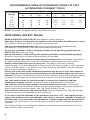
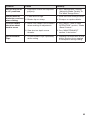
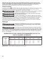
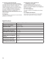
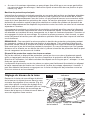
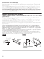
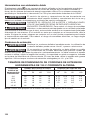
RECOMMENDED SIZES OF EXTENSION CORDS 120 VOLT
ALTERNATING CURRENT TOOLS
Tool's Ampere
Rating
Cord Size in A.W.G. Wire Sizes in mm
2
Cord Length in Feet Cord Length in Meters
25 50 100 150 15 30 60 120
3-6 18 16 16 14 0.75 0.75 1.5 2.5
6-8 18 16 14 12 0.75 1.0 2.5 4.0
8-10 18 16 14 12 0.75 1.0 2.5 4.0
10-12 16 16 14 12 1.0 2.5 4.0 —
12-16 14 12 — — — — — —
NOTE:
The smaller the gauge number, the heavier the cord.
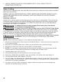
ADDITIONAL SAFETY RULES
MAKE WORKSHOP CHILD-PROOF
with padlocks, master switches.
Make sure the oor is clean and non-slippery or non-skid where the table saw is set up.
If you cannot control your motion, you cannot control the work.
Use only recommended accessories.
Use only accessories recommended by the
manufacturer of your model. Other accessories may be hazardous.
Do not use any blade or other cutting tool marked for an operating speed less than
4600 R.P.M.
Risk of serious injury.
Ensure that blade or other cutting tool, washers and arbor nut are installed properly.
Reference instructions for removal and installation of the blade.
Never operate the saw unless the proper insert is installed.
Make sure the table insert is ush
or slightly below the table surface at the front and ush to slightly above at the rear of insert.
Always inspect table saw prior to every use.
If any part of your saw is missing,
malfunctioning, or has been damaged or broken (such as the motor switch or other operating
control, a safety device, or the power cord), cease operating immediately until the particular
part is properly repaired or replaced.
Plastic and composition (like hardboard) materials may be cut on your saw. However,
since these are usually quite hard and slippery, the anti-kickback pawls may not stop a
kickback.
Therefore, be especially attentive to following proper set-up and cutting procedures
for ripping. Do not stand, or permit anyone else to stand, in line with a potential kickback.
Use extra caution when the guard assembly is removed for resawing, dadoing,
rabbeting or molding.
Replace the guard as soon as that operation is completed.
Use auxiliary facing on miter gauge to increase stability and control.
Crosscutting
operations are more conveniently worked and with greater safety if an auxiliary wood facing
board is attached to the miter gauge. See “Rip Fence Auxiliary Facing.”
Avoid awkward operations and hand positions.
Where a sudden slip could cause ngers
or hand to move into the sawblade or other cutting tool.
If you stall or jam the sawblade in the workpiece, turn saw “OFF” and unplug the tool,
remove the workpiece from the sawblade, and check to see if the sawblade is parallel to
the table slots or grooves and if the spreader is in proper alignment with the sawblade.
If ripping at the time, check to see if the rip fence is parallel with the sawblade. Readjust as
indicated.
Think Safety. Safety is a combination of operator common sense and alertness at all times
when the table saw is being used.

9
SYMBOLS
Safety Symbols
The purpose of safety symbols is to attract your attention to possible dangers. The safety
symbols and the explanations with them deserve your careful attention and understanding.
The symbol warnings do not, by themselves, eliminate any danger. The instructions and
warnings they give are no substitutes for proper accident prevention measures.
WARNING
Be sure to read and understand all safety instructions in this
Operator’s
Manual, including all safety alert symbols such as “
DANGER
,”
“
WARNING
,” and “
CAUTION
” before using this tool. Failure to following all instructions listed
below may result in electric shock, re, and/or serious personal injury.
The denitions below describe the level of severity for each signal word. Please read the manual
and pay attention to these symbols.
This is the safety alert symbol. It is used to alert you to potential
personal injury hazards. Obey all safety messages that follow this
symbol to avoid possible injury or death.
DANGER
DANGER indicates a hazardous situation which, if not avoided, will
result in death or serious injury.
WARNING
WARNING indicates a hazardous situation which, if not avoided, could
result in death or serious injury.
CAUTION
CAUTION, used with the safety alert symbol, indicates a hazardous
situation which, if not avoided, will result in minor or moderate injury.
Damage Prevention and Information Messages
These inform the user of important information and/or instructions that could lead to equipment
or other property damage if they are not followed. Each message is preceded by the word
“NOTICE”, as in the example below:
NOTICE:
Equipment and/or property damage may result if these instructions are not followed.
WARNING
The operation of any power tools can result in
foreign
objects being thrown into your eyes, which can result
in severe eye damage. Before beginning power tool operation, always
wear safety goggles or safety glasses with side shields and a full face
shield when needed. We recommend a Wide Vision Safety Mask for use
over eyeglasses or standard safety glasses with side shields. Always use
eye protection which is marked to comply with ANSI Z87.1.

10
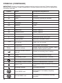
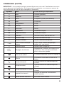
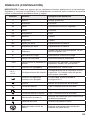
SYMBOLS (CONTINUED)
IMPORTANT:
Some of the following symbols may be used on your tool. Please study them
and learn their meaning. Proper interpretation of these symbols will allow you to operate the
tool better and safer.
Symbol Name Designation/Explanation
V Volts Voltage (potential)
A Amperes Current
Hz Hertz Frequency (cycles per second)
W Watt Power
kg Kilograms Weight
min Minutes Time
s Seconds Time
Wh Watt-hours Battery capacity
Ah Ampere-Hours Battery capacity
Ø Diameter Size of drill bits, grinding wheels, etc.
n
0
No load speed Rotational speed, at no load
n Rated speed Maximum attainable speed
…/min
Revolutions or reciprocation
per minute
Revolutions, strokes, surface speed,
orbits, etc. per minute
0 Off position Zero speed, zero torque...
1,2,3,…
I,II,III,
Selector settings
Speed, torque or position settings. Higher
number means greater speed
Innitely variable selector
with off
Speed is increasing from 0 setting
Arrow Action in the direction of arrow
Alternating current Type or a characteristic of current
Direct current Type or a characteristic of current
Alternating or direct current Type or a characteristic of current
Class II tool
Designates Double Insulated Construction
tools.
Earthing terminal Grounding terminal
Li-ion RBRC seal
Designates Li-ion battery recycling
program
Ni-Cad RBRC seal
Designates Ni-Cad battery recycling
program

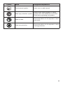
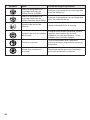
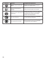
11
Symbol Name Designation/Explanation
Read manual symbol Alerts user to read manual
Wear eye protection symbol
Always wear safety goggles or safety
glasses with side shields and a full face
shield when operating this product.
Wear a mask
Recommendation for the operator to wear
dust mask .
Wear ear protection
Recommendation for the operator to wear
hearing protection .

12
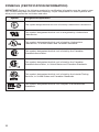
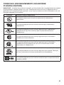
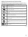
SYMBOLS (CERTIFICATION INFORMATION)
IMPORTANT:
Some of the following symbols for certication information may be used on your
tool. Please study them and learn their meaning. Proper interpretation of these symbols will
allow you to operate the tool better and safer.
Symbol Designation/Explanation
This symbol designates that this tool is listed by Underwriters Laboratories.
This symbol designates that this tool is recognized by Underwriters
Laboratories.
This symbol designates that this tool is listed by Underwriters
Laboratories, to United States and Canadian Standards.
This symbol designates that this tool is listed by the Canadian
Standards Association.
This symbol designates that this tool is listed by the Canadian
Standards Association, to United States and Canadian Standards.
This symbol designates that this tool is listed by the Intertek Testing
Services, to United States and Canadian Standards.
This symbol designates that this tool complies to NOM Mexican
Standards.

13
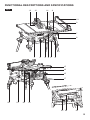
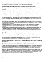
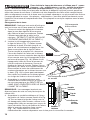
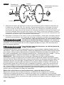
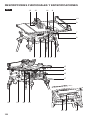
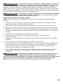
FUNCTIONAL DESCRIPTIONS AND SPECIFICATIONS
Fig. 1
1
HEIG HT
+
2
0
15
30
45
22.5
BLADE ROTATION
2 4 5 6
7
9
10
1213
22 21
25 24 23
18
15
16
17
1114
8
3
20 19

14
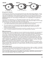
1. Power Switch
Switch incorporates a hole for use with a
padlock to prevent accidental starting.
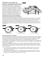
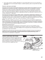
2. Elevation Wheel
Elevates or lowers the blade. Also used to
tilt the blade -2° to 47 °. The cutting capacity
at 0° is 3-1/2”. The cutting capacity at 45° is
2-1/2”.
3. Blade-bevel-lock Lever
Locks the blade to desired bevel angle.
4. Blade-bevel Scale
Shows the degree to which the blade is tilted.
Total range of the bevel is -2° to 47°.
5. Base
Supports the table saw. Includes integrated
carry handle.
6. Push Stick & Storage
Allows you to rip smaller pieces of stock with
a greater level of safety.
7. Rail-driving Wheel Knob
Drives the rail to move it from side to side.
8. Rail-lock Lever
Allows you to lock the fence at desired
distances.
9. Work Support/Auxiliary Fence
Provides support for wider workpieces when
extending the fence beyond the table and for
thinner workpiece with thickness not more
than 3/4” when not extending the fence.
10. Rip Fence
Provides an auxiliary support (in the lower
position) and over-the-table support (upper
position). Securely attaches to rails in 3
positions with lock latches on both ends.
11. Rip-fence Scale
Shows the distance from the blade to the rip
fence 14 inches to left, 25.5 inches to right.
12. Smart Guard System
Consists of three key elements: Riving
Knife (Spreader), Anti-Kickback Device, and
Main Barrier Guard. All of these are part
of a modular system that requires no tools
to assemble or disassemble. This Guard
System must always be in place and working
properly for all through sawing cuts.
13. Table Insert
Removable for removing or installing a blade
or other cutting tools.
14. Miter Gauge
Head can be locked in the desired position
for crosscutting or mitering by tightening the
lock knob. ALWAYS SECURELY LOCK THE
HEAD WHEN IN USE.
15. Table
Provides large working surface to support
the workpiece.
16. Cord Wrap&Storage
Allows you to easily secure the cord so it’s
out of the way when transporting or storing.
17. Miter Gauge Storage
Storage location for the miter gauge when
not in use, or when transporting or storing
the table saw.
18. Rip-fence Storage
Storage location for the rip fence when
transporting or storing the table saw.
19. Dust-Chute Elbow & Storage
Storage location for the dust-chute elbow
when not in use, or when transporting or
storing the table saw.
20. Anti-Kickback Device Storage
Storage location for the anti-kickback device
when not in use, or when transporting or
storing the table saw.
21. Dust Port/Vacuum Hook-Up
Removable to clear any large pieces of wood
trapped inside. Always check to ensure that
the dust port is securely fastened to the table
saw before use. Attach a 2-1/2” vacuum hose
into the dust port for convenient sawdust
removal.
22. Stand
Allows table saw to be raised during use.
23. Main-barrier-guard Storage
Storage location for the Main Barrier Guard
when not in use, or when transporting or
storing the table saw.
24. Wrench & Storage
Wrench for the removal and installation of
saw blades.
25. Carrying Handle
Allows you to carry the table saw with one
hand when it is not in use.

15
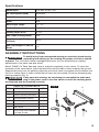
Specications
Rated Input
120 Vac, 60 Hz ,15A
No Load Speed (RPM)
4600/min
Blade Size
10’’(254mm)
Arbor
5/8"
Bevel angle range
-2° - 47°
Cutting Depth at 90°
3-1/2"
Cutting Depth at 45°
2-1/2"
Max. Dado Cutting Width
5/8"
Max. Rip Length To Right
Of Blade
25.5"
Max. Rip Length To Left Of
Blade
14’’
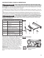
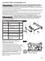
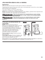
ASSEMBLY INSTRUCTIONS
WARNING
To avoid injury from unexpected starting or electrical shock during
unpacking and setting up, do not plug the power cord into a source
of power.
This cord must remain unplugged whenever you are assembling or making
adjustments to the table saw with stand.
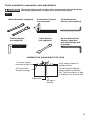
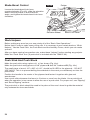
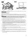
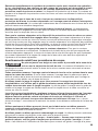
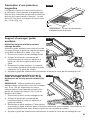
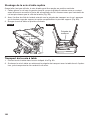
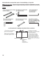
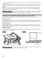
Model TS6307-00 Table Saw and stand is shipped completely in one carton. To make the
assembly of the stand easier, place the table saw with the table surface towards the ground.
Separate all parts from the packing materials and check each one against the illustration and
the list of Loose Parts to make certain that all items are accounted for before discarding any
packing material (Fig. 2).
WARNING
If any parts are missing, do not attempt to assemble the table saw,
plug in the power cord or turn the switch on until the missing parts
are obtained and are installed correctly.
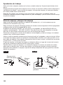
TABLE OF LOOSE PARTS
ITEM DESCRIPTION QTY.
1 Dust-Chute Elbow 1
2 Barrier-Guard Assembly 1
3 Anti-Kickback Device 1
4 Miter Gauge 1
5 Push Stick 1
6 Rip Fence 1
7
Drive Knob with Washer
and Hex Screw
1
Fig. 2
1
2
6
3
4 5 7

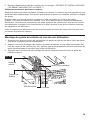
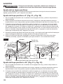
16
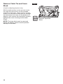
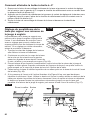
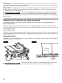
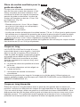
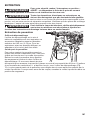
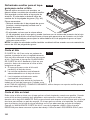
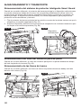
Remove Cable Tie and Foam
Block
(Used for shipping purpose only)
With the table surface on the ground, locate
the cable tie that anchors the motor/blade
assembly to the base. Using scissors or wire
cutters, cut and remove the cable tie. Release
the blade bevel lock lever, tilt the blade to 45
degrees, then remove the foam block located
between the motor housing and the table.
(Fig.3)
NOTE:
The foam block must be removed
before the blade is raised to avoid possible
damage to the blade.
Fig. 3
Remove Styrofoam
Block

17
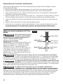
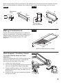
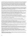
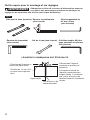
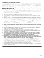
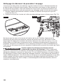
Tools needed for assembly and adjustment
WARNING
Disconnect the plug from the power source before performing any
assembly, adjustment or repair to avoid possible injury.
Blade Wrenches (supplied)
Framing Square
(not supplied)
3/4” board with
straight top edge
Drawn line
No gap or
overlap
1.Position square
and draw a light line
2.Flip square (shown in
dotted position)
3.Check edge of ipped
square against the drawn
line. There should be no gap
or overlap at the bottom end.
10mm Wrench
(not supplied)
Double-Ended Allen
Wrench, 6mm Hex,
with PH2 Phillips end
(supplied)
COMBINATION SQUARE MUST BE TRUE
Combination Square
(not supplied)
2.5mm/5mm Hex
Wrench (not supplied)
Fig. 4

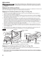
18
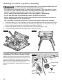
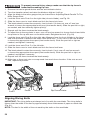
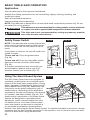
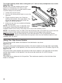
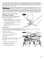
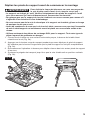
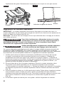
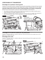
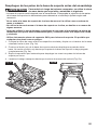
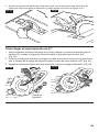
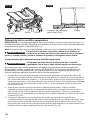
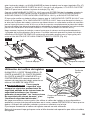
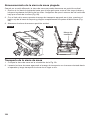
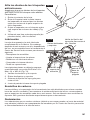
Unfolding The Stand Legs Before Assembly
WARNING
To reduce the risk of personal injury, do not operate table saw until
you have read and understand the followings:
•
The table saw is integrated with the stand when shipped. Check the stand to make
sure that it is still securely fastened to the table saw before any operation. A loose
stand is unstable and may shift in use and cause serious injury.
•
Do not stand on the table saw stand or use it as a ladder or scaffolding.
•
Do not use table saw if the stand tips, slides, or moves in any way.
•
Before operating the table saw, ensure that the entire table-saw/stand assembly is
secure and placed on solid, level surface.
•
Use only SKIL replacement parts for the stand. Any others may create a hazard.
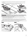
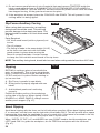
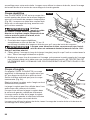
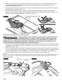
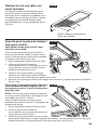
1. Place the table saw on a clean level surface with the tabletop facing the ground (Fig.5a).
2. Press the red button of the stand while unfolding the stand leg. Do not release the red
button until the stand leg has been folded completely (Fig.5a).
3. Repeat the above operation to unfold the other three stand legs in turn.
4. Lift the carrying handle until the table saw is vertical (Fig.5b).
Fig. 5a
Fig. 5b
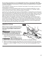
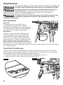
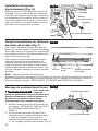
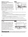
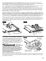
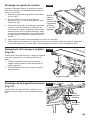
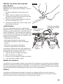
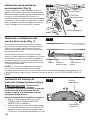
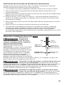
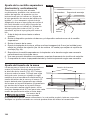
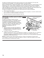
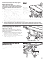
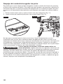
Installing The Drive Knob (Fig.6)
Attach the drive knob onto the mounting hole.
While holding the drive knob to prevent it from
moving, install the included hex screw and
washer into the drive knob and the mounting
hole , then use the Double-Ended Allen
Wrench (included) to secure the hex screw in
place.
Fig. 6
Mounting
Hole
Drive Knob
Washer
Hex Screw

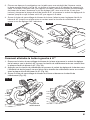
19
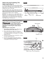
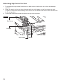
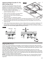
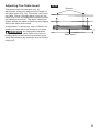
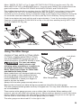
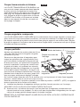
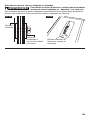
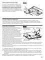
Removing and Installing The
Table Insert (Fig.7)
To remove table insert, press the button with
your thumb and place your index nger into the
nger hole to lift and pull the table insert out
toward the front of the saw.
To install table insert, align and insert the two
tabs on table insert with the two pockets in the
tabletop and pivot the table insert downwards.
Verify that the table insert is seated.
NOTICE:
The table insert is adjustable and,
therefore, can change over time. Verify that the
table insert is set correctly before every use.
If adjustment is needed, follow the “Adjusting
The Table Insert” instructions.
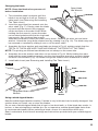
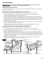
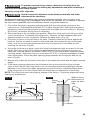
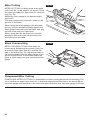
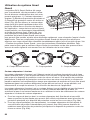
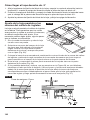
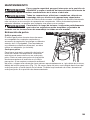
Attaching the Smart Guard System
WARNING
To prevent personal
injury, always disconnect
the plug from the power source before
attaching or removing the Smart Guard
System.
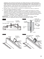
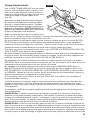
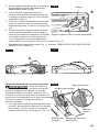
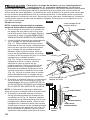
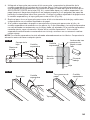
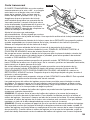
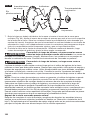
Positioning the riving knife
1. Remove the table insert (see “Removing
and Installing The Table Insert ”).
2. Raise the blade as high as it will go by
turning the elevation wheel clockwise and
set it perpendicular to the table (0° on bevel
scale) (Fig. 8).
3. Rotate the release lever clockwise, so that
it points upward (Fig. 8).
4. Pull the riving knife toward the release
lever to disengage the upper hole of the
riving knife from the pin (Fig.9).
Fig. 7
1
2
Fig. 8
B
Release Lever
Fig. 9
Upper Hole of the Riving Knife
Button
Finger Hole
Table Insert
Riving Knife
Pin

20
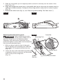
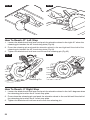
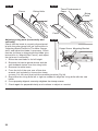
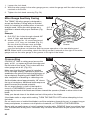
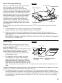
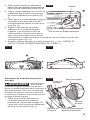
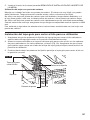
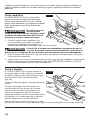
5. Slide the riving knife up to its highest position so that it is directly over the center of the
blade (Fig. 10).
6. Align and engage the lowest hole in riving knife with the pin, then lock the release lever by
rotating it counterclockwise. Push/pull on the riving knife to verify that it is locked in place
(Fig. 10).
7. Replace the table insert (Fig.11), see “Removing and Installing The Table Insert ”).
1
2
Fig. 10
Fig. 11
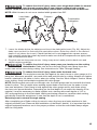
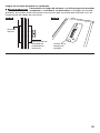
Attaching the main barrier guard
WARNING
Before attaching the main
barrier guard, make sure to
slide the riving knife to its highest position.
Otherwise, the main barrier guard will not be
positioned rightly in place and could increase the
risk of serious personal injury.
1. With one hand, hold the front of the main
barrier guard by the mounting fork. With the
other hand, lift the guard-release lever up
(Fig. 12).
2. Lower the rear of the main barrier guard and
completely slide the cross bar into the middle
notch on top of the riving knife
(Fig. 12).
Fig. 12
Guard-Release Lever
Mounting Fork
Guard
Barriers
Cross Bar
Middle Notch
La page est en cours de chargement...
La page est en cours de chargement...
La page est en cours de chargement...
La page est en cours de chargement...
La page est en cours de chargement...
La page est en cours de chargement...
La page est en cours de chargement...
La page est en cours de chargement...
La page est en cours de chargement...
La page est en cours de chargement...
La page est en cours de chargement...
La page est en cours de chargement...
La page est en cours de chargement...
La page est en cours de chargement...
La page est en cours de chargement...
La page est en cours de chargement...
La page est en cours de chargement...
La page est en cours de chargement...
La page est en cours de chargement...
La page est en cours de chargement...
La page est en cours de chargement...
La page est en cours de chargement...
La page est en cours de chargement...
La page est en cours de chargement...
La page est en cours de chargement...
La page est en cours de chargement...
La page est en cours de chargement...
La page est en cours de chargement...
La page est en cours de chargement...
La page est en cours de chargement...
La page est en cours de chargement...
La page est en cours de chargement...
La page est en cours de chargement...
La page est en cours de chargement...
La page est en cours de chargement...
La page est en cours de chargement...
La page est en cours de chargement...
La page est en cours de chargement...
La page est en cours de chargement...
La page est en cours de chargement...
La page est en cours de chargement...
La page est en cours de chargement...
La page est en cours de chargement...
La page est en cours de chargement...
La page est en cours de chargement...
La page est en cours de chargement...
La page est en cours de chargement...
La page est en cours de chargement...
La page est en cours de chargement...
La page est en cours de chargement...
La page est en cours de chargement...
La page est en cours de chargement...
La page est en cours de chargement...
La page est en cours de chargement...
La page est en cours de chargement...
La page est en cours de chargement...
La page est en cours de chargement...
La page est en cours de chargement...
La page est en cours de chargement...
La page est en cours de chargement...
La page est en cours de chargement...
La page est en cours de chargement...
La page est en cours de chargement...
La page est en cours de chargement...
La page est en cours de chargement...
La page est en cours de chargement...
La page est en cours de chargement...
La page est en cours de chargement...
La page est en cours de chargement...
La page est en cours de chargement...
La page est en cours de chargement...
La page est en cours de chargement...
La page est en cours de chargement...
La page est en cours de chargement...
La page est en cours de chargement...
La page est en cours de chargement...
La page est en cours de chargement...
La page est en cours de chargement...
La page est en cours de chargement...
La page est en cours de chargement...
La page est en cours de chargement...
La page est en cours de chargement...
La page est en cours de chargement...
La page est en cours de chargement...
La page est en cours de chargement...
La page est en cours de chargement...
La page est en cours de chargement...
La page est en cours de chargement...
La page est en cours de chargement...
La page est en cours de chargement...
La page est en cours de chargement...
La page est en cours de chargement...
La page est en cours de chargement...
La page est en cours de chargement...
La page est en cours de chargement...
La page est en cours de chargement...
La page est en cours de chargement...
La page est en cours de chargement...
La page est en cours de chargement...
La page est en cours de chargement...
La page est en cours de chargement...
La page est en cours de chargement...
La page est en cours de chargement...
La page est en cours de chargement...
La page est en cours de chargement...
La page est en cours de chargement...
La page est en cours de chargement...
La page est en cours de chargement...
La page est en cours de chargement...
La page est en cours de chargement...
La page est en cours de chargement...
La page est en cours de chargement...
La page est en cours de chargement...
La page est en cours de chargement...
La page est en cours de chargement...
La page est en cours de chargement...
La page est en cours de chargement...
La page est en cours de chargement...
La page est en cours de chargement...
La page est en cours de chargement...
La page est en cours de chargement...
La page est en cours de chargement...
La page est en cours de chargement...
La page est en cours de chargement...
La page est en cours de chargement...
La page est en cours de chargement...
La page est en cours de chargement...
La page est en cours de chargement...
La page est en cours de chargement...
La page est en cours de chargement...
La page est en cours de chargement...
La page est en cours de chargement...
La page est en cours de chargement...
La page est en cours de chargement...
La page est en cours de chargement...
La page est en cours de chargement...
La page est en cours de chargement...
La page est en cours de chargement...
La page est en cours de chargement...
La page est en cours de chargement...
La page est en cours de chargement...
La page est en cours de chargement...
La page est en cours de chargement...
La page est en cours de chargement...
La page est en cours de chargement...
La page est en cours de chargement...
La page est en cours de chargement...
La page est en cours de chargement...
La page est en cours de chargement...
La page est en cours de chargement...
-
 1
1
-
 2
2
-
 3
3
-
 4
4
-
 5
5
-
 6
6
-
 7
7
-
 8
8
-
 9
9
-
 10
10
-
 11
11
-
 12
12
-
 13
13
-
 14
14
-
 15
15
-
 16
16
-
 17
17
-
 18
18
-
 19
19
-
 20
20
-
 21
21
-
 22
22
-
 23
23
-
 24
24
-
 25
25
-
 26
26
-
 27
27
-
 28
28
-
 29
29
-
 30
30
-
 31
31
-
 32
32
-
 33
33
-
 34
34
-
 35
35
-
 36
36
-
 37
37
-
 38
38
-
 39
39
-
 40
40
-
 41
41
-
 42
42
-
 43
43
-
 44
44
-
 45
45
-
 46
46
-
 47
47
-
 48
48
-
 49
49
-
 50
50
-
 51
51
-
 52
52
-
 53
53
-
 54
54
-
 55
55
-
 56
56
-
 57
57
-
 58
58
-
 59
59
-
 60
60
-
 61
61
-
 62
62
-
 63
63
-
 64
64
-
 65
65
-
 66
66
-
 67
67
-
 68
68
-
 69
69
-
 70
70
-
 71
71
-
 72
72
-
 73
73
-
 74
74
-
 75
75
-
 76
76
-
 77
77
-
 78
78
-
 79
79
-
 80
80
-
 81
81
-
 82
82
-
 83
83
-
 84
84
-
 85
85
-
 86
86
-
 87
87
-
 88
88
-
 89
89
-
 90
90
-
 91
91
-
 92
92
-
 93
93
-
 94
94
-
 95
95
-
 96
96
-
 97
97
-
 98
98
-
 99
99
-
 100
100
-
 101
101
-
 102
102
-
 103
103
-
 104
104
-
 105
105
-
 106
106
-
 107
107
-
 108
108
-
 109
109
-
 110
110
-
 111
111
-
 112
112
-
 113
113
-
 114
114
-
 115
115
-
 116
116
-
 117
117
-
 118
118
-
 119
119
-
 120
120
-
 121
121
-
 122
122
-
 123
123
-
 124
124
-
 125
125
-
 126
126
-
 127
127
-
 128
128
-
 129
129
-
 130
130
-
 131
131
-
 132
132
-
 133
133
-
 134
134
-
 135
135
-
 136
136
-
 137
137
-
 138
138
-
 139
139
-
 140
140
-
 141
141
-
 142
142
-
 143
143
-
 144
144
-
 145
145
-
 146
146
-
 147
147
-
 148
148
-
 149
149
-
 150
150
-
 151
151
-
 152
152
-
 153
153
-
 154
154
-
 155
155
-
 156
156
-
 157
157
-
 158
158
-
 159
159
-
 160
160
-
 161
161
-
 162
162
-
 163
163
-
 164
164
-
 165
165
-
 166
166
-
 167
167
-
 168
168
-
 169
169
-
 170
170


Skil TS6307-00 Le manuel du propriétaire
- Catégorie
- Outils électroportatifs
- Taper
- Le manuel du propriétaire
dans d''autres langues
- English: Skil TS6307-00 Owner's manual
- español: Skil TS6307-00 El manual del propietario
Documents connexes
Autres documents
-
Bosch 4100 Manuel utilisateur
-
SKILSAW SPT99-12 Manuel utilisateur
-
Bosch GTS1031 Le manuel du propriétaire
-
-
Bosch Power Tools 4100DG Manuel utilisateur
-
Bosch Appliances 4100 - 10 Inch Worksite Table Saw Manuel utilisateur
-
Ryobi PGC21B Le manuel du propriétaire
-
-
-
Makita 5621RD Manuel utilisateur