Blodgett Microwave Oven XR8-G Manuel utilisateur
- Catégorie
- Cuisinières
- Taper
- Manuel utilisateur
Ce manuel convient également à

BLODGETT OVEN COMPANY
www.blodgett.com
44 Lakeside Avenue, Burlington, Vermont 05401 USA Telephone (800) 331-5842, (802) 860-3700 Fax: (802)864-0183
PN 38480 Rev A (8/05)
E 2005 --- G.S. Blodgett Corporation
XR8 -G
MINI RACK OVEN
INSTALLATION -- OPERATION -- MAINTENANCE
XR8 -G
MINI RACK OVEN
MANUEL D’INSTALLATION -- FONCTIONNEMENT -- ENTRETIEN

IMPORT
A
NT
FORYOURSAFETY
Do not store or use g asoline or other flammable vapors or liquids in the vicinity
of this or any other appliance.
AVERTIS SEMENT
Ne pas entreposer ni utiliser de l’essence ni d’autres vapeurs ou liquides inflam-
mables dans le vois in a ge de cet appar iel, ni de tout autr e appar eil.
INSTRUCTIONS (PAGE 12) TO BE FOLLOWED IN THE EVENT THE USER
SMELLS GAS MUST BE POSTED IN A PROMINENT LOCATION. THIS INFORMA-
TION MAY BE OBTAINED BY CONTACTING YOUR LOCAL GAS SUPPLIER.
LESINSTRUCTIONS (PAGE 12) À RESPECTER AUCASOÙ L’UTILISATEUR PER-
ÇOIT UNE ODEUR DE GAZ DOIVENT ÊTRE AFFICHÉES DANS UN ENDROIT BIEN
VISIBLE. VOUS POUVEZ VOUS LES PROCURER AUPRÈS DE VOTRE FOURNIS-
SEUR DE GAZ LOCAL.
WARNING: IMPROPER INSTALLA TION, ADJUSTMENT, ALTERA TION, SERVICE OR
MAI NTEN A NC E CAN CA US E PROP ERTY DAMAG E, INJURY OR DEATH. READ THE
INST ALLA TION, OPERA TING AND MAINTENANCE INSTRUCTIONS THOROUGHLY
BEFORE INST ALLING OR SERVICING THIS EQUIPMENT
A V ERTI SSEMEN T: UNE INSTALLATION, UN AJUSTEMEN T, UNE ALTÉRATION , UN
SERV IC E OU UN ENTRETI EN NON CONFO RME A UX NORMES PEUT CA US ER DES
DO MMA GES À LA PROP RI ÉTE, DES BLESSURES OU LA MORT. LIS EZ ATTENTIV E-
MENT LES DIREC TI V ES D’ I NS TALL ATION, D’O P ÉRATION ET D’ ENTRETI EN AV A N T
DE FAIRE L’IN S TALLATION OU L’ENTRETIEN DE CET ÉQUI P EMEN T.
The information contained in thi s manual is important for the proper installation,
use, and maintenance of this oven. Adherence to these procedures and instruc-
tions will result in satisfactory baking results and long, trouble free service.
Please read this manual carefully and retain it for future reference.
Les info r m a t ions données da ns le présent manuel sont impor tantes pour installer,
utiliser et entr et enir co r r ect em ent ce fou r. Le r es pect de ces ins tructio n s et pro cé-
dures permettra d’obtenir de bons résultats de cuisson et une longue durée de ser-
vice sans problèmes. Veuillez lire le présent manuel et le conserver pour pouvoir
vou s y repor t er à l’avenir.
Errors: Descriptive, typographic or pictorial errors are subject to correction. Specifica-
tions are subject to change without notice.
Erreurs:Les erreurs de description, de typographie ou d’illustration font l’objet de
corrections. Les caractéristiques sont sujettes à modifications sans préavis.

THE REPUTATION YOU CAN COUNT ON
UNE RÉPUTATION SUR LAQUELLE VOUS POUVEZ COMPTER
For over a century and a half, The Blodgett Oven Company has been building
ovens and nothing but ovens. We’ve set the industry’s quality standard for all
kinds of ovens for every foodservice operation regardless of size, a pplication
or budget. In fact, no one offers more models, sizes, and oven applications
than Blodgett; gas and electric, full-size, half-size, countertop and deck, con-
vection, Cook’n Hold, Combi-Ovens and the industry’s highest quality Pizza
Oven line. For more information on the full line of Blodgett ovens contact your
Blodgett representative.
Cela fait maintenant dessus un siècle et demi que Blodgett se spécialise dans
la fabrication de fours. Nous avons établi les normes de qualité qui s’appli-
quent dans l’industrie à tous les types de fours utilisés dans les services ali-
mentaires, quel qu’en soit la taille, l’exploitation ou le budget. En fait, ni n’offre
plus de modèles, de tailles et d’applications de fours que Blodgett. À gaz et
électriques. De tailles différentes, sur plan de travail et superposables. Qu’il
s’agisse de fours à convection, des modèles Cook’n Hold et Combi-Oven, ou
de la gamme de fours à pizzas de la plus haute qualité offerte sur le marché.
Pour de plus amples informations sur la gamme complète de fours B lodgett,
veuillez contacter votre représentant B lodgett.

Your Service Agency’s Address:
Adressedevotreagencedeservice:
Model/Modèle:
Serial Number/Numéro de série:
Your oven was installed by/
Installateur de votre four:
Your oven’s installation was checked by/
Contrôleur de l’installation de votre four:

Table of Contents/Table des Matières
Introduction
Oven Description and Specifications 2....
Installation
Delivery and Location 3.................
Oven Assembly 4......................
Assembly to Stand 4..................
Assembly to Optional Proofer 4.........
V entilation 5...........................
Utility Connections ---
Standards and Codes 6.................
Gas Connection 7......................
Plumbing and Electrical Connections 10...
Initial Startup 11.........................
Operation
Safety Information 12....................
Standard Control 13.....................
General Guidelines for
Operating Personnel 15..................
Maintenance
Cleaning and Preventative Maintenance 16.
Troubleshooting Guide 17................
Introduction
Description et Spécifications du Four 18....
Installation
Livraison et Implantation 19...............
Montage du Four 20.....................
Assembly to stand 20..................
Assembly to optional proofer 20.........
V entilation 21...........................
Branchements de Service ---
Normes et Codes 22.....................
Branchement de Gaz 23.................
Raccordement Électrique et Plomberie 26..
Mise en Marche Initiale 27................
Utilisation
Informations de Sécurité 28...............
Standard Control 29.....................
Consignes Générales à l’Intention
des Utilasateurs 31......................
Entretien
Nettoyage et Entretien Préventif 32........
GuidedeDétectiondesPannes 33........

Introduction
2
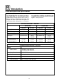
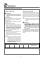
Oven Description a nd Specifications
The Blodgett M ini -Rack oven features a continu-
ously rotating eight pan rack and unique airflow
system that moves large amounts of air at low ve -
locity to ensure a consistently even bake. The
Blodgett rack slide sytem allows the operator t o
quickly adjust slide spacing from 1 to 4 inches in
any configuration. In addition, the Mini-Rack oven
is capable of producing large volumes of steam for
bagels or similar products.
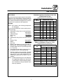
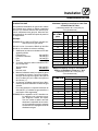
GAS SPECIFICATIONS -- XR8-G/AA
Natural Gas Propane Gas
US Units SI Units US Units SI Units
Heating V alue 1000 BTU/cu. ft. 37.3 MJ/m
3
2550 BTU/cu. ft. 95.0 MJ/m
3
Specific Gravity (air=1.0) 0.63 0.63 1.53 1.53
Gas Manifold Pressure 3.5” W.C. .87 kPa 10” W.C. 2.5 kPa
Oven Input 110,000 BTU/hr 32 kW
116 MJ/hr
110,000 BTU/hr 32 kW
116 MJ/hr
Main Burner Orifice Size:
Six burners are
Two burners are
.07” dia.
.061” dia.
1.7 mm
1.5 mm
.043” dia.
.038” dia.
1.0 mm
0.96 mm
PLUMBING SPECIFICATIONS -- XR8-G/AA
Water
Water Pressure 30 PSI (21 kPa) minimum
75 PSI (52 kPa) maximum
Water Connection 3/4” MGHT
Flow Rate 1.12 gallon/minute (4.24 litre/minute) minimum
Drainage
Drain Connection 3/4” rear drain to air gap drain

Installation
3
Delivery and Location
DELIVERY AND INSPECTION
All Blodgett ovens are shipped in containers to
prevent damage. Upon delivery of your new oven:
D Inspect the shipping container for external dam-
age. Any evidence of damage should be noted
on the delivery receipt which must be signed by
the driver.
D Uncrate the oven and check for internal dam-
age. Carriers will accept claims for concealed
damage if notified within fifteen days of delivery
and the shipping container is retained for in-
spection.
The Blodgett Oven Company cannot assume
responsibility for loss or damage suffered in
transit. The carrier assumed full responsibility
for delivery in good order when the shipment
was a ccepted. We are, however, prepa red to
assist you if filing a cla im is necessary.
OVEN LOCATION
The well planned and proper placement of your
oven will result in long term operator convenience
and satisfactory performance.
The following clearances must be maintained be-
tween the oven and any combustible or non-com-
bustible construction.
D Oven body right side --- 0” (0 cm)
D Oven body left side --- 0” (0 cm)
D Oven body back --- 0” (0 cm)
D Oven top --- 12” (30.5 cm)
The following clearances must be available for ser-
vicing.
D Oven body sides --- 12” (30 cm)
D Oven body back --- 12” (30 cm)
D Oven top --- 12” (30.5 cm)
NOTE: On gas models, routine servicing can usu-
ally be accomplished within the limited
movement provided by the gas hose re-
straint. If the oven needs to be moved fur-
ther from the wall, the gas must first be
turned off and disconnected from the oven
before removing the restraint. Reconnect
the restraint after the oven has been re-
turned to its normal position.
It is essential that a n adequate air supply to the
oven be maintained to provide a sufficient flow of
combustion and ventilation air.
D Place the oven in an area that is free of drafts.
D Keep the oven area free and clear of all combus-
tibles such as paper, cardboard, and flammable
liquids and solvents.
D Do not place the oven on a curb ba se or seal to
a wall. This will restrict the flow of air and prevent
proper ventilation. Tripping of the blower mo-
tor’s thermal overload device is caused by an
excessive ambient temperature on the right
side of the oven. This condition must be cor-
rected to prevent permanent damage to the
oven.
D The locatio n must provide adequate clearance for
the air opening into the burners.
Before making any utility connections to this oven,
check the rating plate to be sure the oven specifi-
cations are compatible with the gas and electrical
services supplied for the oven.
1. The rating plate is located behind the control
panel.
2. Remove the two screws on the right side of the
control panel.
3. Pull the control panel toward the right side of
the oven.
4. Pull the control panel away from the oven and
rotate out.
5. Reverse steps 2-4 t o close the control panel.

Installation
4
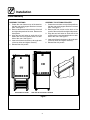
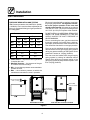
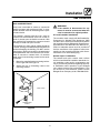
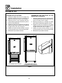
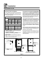
Oven Assembly
ASSEMBLY TO STAND
1. Center the oven frame on top of the stand so
that the oven overhangs at both the front and
back. See Figure 1.
2. Remove the three screws at the top of the left
and right side panels of the oven. Remove the
side panels.
3. Align the two bolt holes on each side of the
stand with the two threaded holes on each
sideoftheoven.SeeFigure1.
4. Insert a bolt from the bottom up through each
of the two holes and tighten securely.
5. Reinstall t he side panels.
ASSEMBLY TO OPTIONAL PROOFER
1. Center the oven frame on top of the proofer so
that the oven overhangs at both the front and
back. See Figure 1.
2. Remove the four screws on the back of the
proofer. Remove t he left and right side panels.
3. Align the two bolt holes on each side of the
proofer with the two threaded holes on each
sideoftheoven.SeeFigure1.
4. Insert a bolt from the bottom up through each
of the two holes and tighten securely.
5. Reinstall t he side panels.
SIDE VIEW WITH OPTIONAL PROOFERSIDE VIEW WITH STAND
Figure 1

Installation
5
Ventilation
On gas models the installation of a proper ventila-
tion system cannot be over emphasized. This sys-
tem removes unwanted vapors and products of
combustion from the operating area.
U.S. and Canadian installations
Refer to your local ventilation codes. In the ab-
sence of local codes, refer to the National ventila-
tion code titled, “Standard for the Installation of
Equipment for the Removal of Smoke and Grease
Laden Vapors from Commercial Cooking Equip-
ment”, NFPA-96-Latest Edition.
General export installations
Installation must conform with Local and National
installation standards. Local installation codes
and/or requirements may vary. If you have any
questions regarding the proper installation and/or
operation of your Blodgett oven, please contact
your local distributor. I f you do not have a local dis-
tributor, please call the Blodgett Oven Company at
0011-802-860-3700.
WARNING:
Failure to properly vent the oven can be
hazardous to the health of the operator
and may result in operational problems,
unsatisfactory baking and possible dam-
age to the equipment.
Damage sustained as a direct result of im-
proper ventilation will not be covered by
the manufacturer’s warranty.
CANOPY TYPE EXHAUST HOOD
A mechanically driven, canopy type exhaust hood
is the preferred method of ventilation. The exhaust
fan should have an interlock switch with the oven
to prevent the oven from operating when the ex-
haust fan is not running.
The hood should be sized to completely cover the
equipment plus an overhang of at least 6” (15 cm)
on all sides not adjacent t o a wall. The distance
from the floor to the lower edge of the hood should
not exceed 7’ (2.1m).
The total makeup and exhaust air requirements for
hood capacity should be approximately 35 CFM
(.99 m
3
/min).

Installation
6
Utility Connections --- Standards and Codes
THE INST ALLA TION INSTRUCTIONS CONT AINED
HEREIN ARE FOR THE USE OF QUALIFIED IN-
ST ALLA TION AND SERVICE PERSONNEL ONLY.
INSTALLATION OR SERVICE B Y OTHER THAN QU-
ALIF IED PERSO N N EL MA Y RESULT IN DAMAGE
TO THE OVEN AND/OR INJURY TO THE OPERA-
TOR.
Qualified installation personnel are individuals, a
firm, a corporation, or a company which either in
person or through a representative are engaged
in, and responsible for:
D the installation or replacement of gas piping
and the connection, installation, repair or serv-
icing of equipment.
D the installation of electrical wiring from the elec-
tric meter, main control box or service outlet to
the electric appliance.
Qualified installation personnel must be experi-
enced in such work, familiar with all precautions
required, and have complied w ith all requirements
of state or local authorities having jurisdiction.
U.S. and Canadian installations
Installation must conform with local codes, or in
the absence of local codes, with the ANSI Z83.11a-
CSA 1.8a-2004 Gas Food Service Equipment as
applicable.
Installation must conform with local codes, or in
the absence of local codes, with the National Elec-
trical Code, ANSI/NFPA 70 ---Latest Edition and/or
CSA 22.1 as applicable.
General export installations
Installation must conform with Local and National
installation standards. Local installation codes
and/or requirements may vary. If you have any
questions regarding the proper installation and/or
operation of your Blodgett oven, please contact
your local distributor. I f you do not have a local dis-
tributor, please call t he Blodgett Oven Company at
0011-802-860-3700.

Installation
7
Gas Connection
GAS PIPING
A properly sized gas supply system is essential for
maximum oven performance. Piping should be
sized to provide a supply of gas sufficient to meet
the maximum demand of all appliances on the line
without loss of pressure at the equipment.
Example:
NOTE: BTU values in the following example are
for natural gas.
YoupurchaseaXR8-Grackoventoaddtoyourex-
isting cook line.
1. Add the BTU rating of your current appliances.
Pitco Fryer 120,000 BTU
6 Burner Range 60,000 BTU
Deck Oven 50,000 BTU
Total 230,000 BTU
2. Add the BTU rating of t he new oven to the to-
tal.
Previous Total 230,000 BTU
XR8-G 110,000 BTU
New Total 340,000 BTU
3. Measure the distance from the gas meter to
the cook line. This is the pipe length. Let’s say
thepipelengthis30’(9.1m)andthepipesize
is 1” (2.54 cm).
4. Use the appropriate table to determine the to -
tal capacity of your current gas piping.
The total capacity for this example is 375,000
BTU. Since the total required gas pressure,
340,000 BTU is less than 375,000 BTU, the
current gas piping will not have to be in-
creased.
NOTE: The BTU capacities given in the tables are
for straight pipe lengths only. Any elbows
or other fittings will decrease pipe capaci-
ties. Contact your local gas supplier if you
have any questions.
Maximum Capacity of Iron Pipe in Cubic Feet
of Natural Gas Per Hour
(Pressure drop of 0.5 Inch W.C.)
Pipe
L
h
(
f
)
Nominal Size, Inches
p
Length (ft)
3/4” 1” 1-1/4” 1-1/4” 2”
10 360 680 1400 2100 3950
20 250 465 950 1460 2750
30 200 375 770 1180 2200
40 170 320 660 990 1900
50 151 285 580 900 1680
60 138 260 530 810 1520
70 125 240 490 750 1400
80 118 220 460 690 1300
90 110 205 430 650 1220
100 103 195 400 620 1150
From the National Fuel Gas Code Part 10 Table 10-2
Maximum Capacity of Pipe in Thousands of
BTU/hr of Undiluted L.P. Gas at 11” W.C.
(Pressure drop of 0.5 Inch W.C.)
Pipe Length
(
f
)
Outside Diameter, Inches
p
g
(ft)
3/4” 1” 1-1/2”
10 608 1146 3525
20 418 788 2423
30 336 632 1946
40 287 541 1665
50 255 480 1476
60 231 435 1337
70 215 404 1241
80 198 372 1144
90 187 351 1079
100 175 330 1014
From the National Fuel Gas Code Part 10 Table 10-15

Installation
8
Gas Connection
PRESSURE REGULATION AND TESTING
XR8-G ovens are rated at 110,000 BTU/Hr. (32 kW)
(116 MJ/hr). Each oven has been adj usted at the
factory to operate with the type of gas specified on
the rating plate.
Inlet Pressure
Natural Propane
Min Max Min Max
W.C. 6.0 14.0 11.0 14.0
kPa 1.2 3.5 2.7 3.5
Manifold Pressure
Natural Propane
W.C. 3.5 10.0
kPa .87 2.5
D Inlet Pressure --- the pressure of the gas before
it reaches the oven.
D Manifold Pressure --- the pressure of the gas
as it enters the main burner(s).
D Min --- the minimum pressure recommended to
operate the oven.
D Max --- the maximum pressure at which the
manufacturer warrants the oven’s operation.
Each oven is supplied with a regulator to maintain
the proper gas pressure. The regul ator is essen-
tial to the proper operation of the oven and
should not be removed. It is preset to provide the
oven with 3.5” W.C. (.87 kPa) for natural gas and
10.0” W. C. (2.5 kPa) for Propane at the manifold.
DO NOT INSTALL AN ADDITIONAL REGULATOR
WHERE THE OVEN CONNECTS TO THE GAS
SUPPLY UNLESS THE INLET PRESSURE IS
ABOVE MAXIMUM.
Prior to connecting the oven, gas lines should be
thoroughly purged of all metal filings, shavings,
pipe dope, and other debris. After connection, the
oven should be checked for correct gas pressure.
The oven and its individual s hutoff valve must be
disconnected from the gas supply piping system
during any pressure testing of that system at test
pressuresinexcessof1/2psig(3.45kPa).
The oven must be isolated from the gas supply
piping system by closing its individual manual
shutoff valve during any pressure testing of the
gas piping system at test pressures equal or less
than 1/2 psig (3.45kPa).
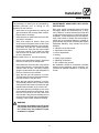
Gas Connection
2.78” (71 mm)
Gas Connection
37.83 (961mm)
SIDE VIEW WITH STAND
Gas Connection
53.62 (1362)
SIDE VIEW WITH OPTIONAL PROOFER
Figure 2

Installation
9
Gas Connection
GAS HOSE RESTRAINT
If the oven is mounted on casters, a commercial
flexible connector with a minimum of 3/4” (1.9 cm)
inside diameter must be used along with a quick
connect device.
The restraint, supplied with the oven, must be
used to limit t he movement of the unit so that no
strain is placed upon the flexible connector. With
the restraint fully stretched the connector should
be easy to install and quick connect.
The restraint (ie: heavy gauge cable) should be
1,000 lb. (453 kg) test load and should be attached
without damaging the building. D O NOT use the
gas piping or electrical conduit for the attachment
of the permanent end of the restraint! Use anchor
bolts in concrete or cement block. On wooden
walls, drive hi test wood lag screws into the studs
of the wall.
1. Mount the supplied bracket to the leg bolt be-
low the gas inlet. See Figure 3.
2. Attach the clip on restraining cable to the
mounting bracket.
Restraint Cable
Bracket
Back of Oven
Figure 3
WARNING!!
If the restraint is disconnected for any
reaso n it must be reconnected when the
oven is returned to its original position.
U.S. and Canadian installations
The connector must comply with the Standard for
Connectors for Movable Gas Appliances, ANSI
Z21.69
S
CSA 6.16 and a quick disconnect device
that complies with the Standard for Quick- Discon-
nect Devices for Use With Gas Fuel, ANSI Z21.41
S
CSA 6.9. Adequate means must be provided to
limit the movement of the appliance without de-
pending on the connection and the quick discon-
nect device or its associated piping.
General export installations
The restraint and quick connect must conform
with Local and National installation standards. Lo-
cal installation codes and/or requirements may
vary. If you have any questions regarding t he prop-
er installation and/or operation of your Blodgett
oven, please contact your local distributor. If you
do not have a local distributor, please call the
Blodgett Oven Company at 0011-802-860-3700.

Installation
10
Plumbing and Electrical Connections
PLUMBING CONNECTIONS
WARNING!!
Plumbing connections must comply with
applicable sanitary, safety and plumbing
codes.
Water Connections
Water supply should meet the following condi-
tions. Consult your local water company before
installing the oven.
D Hardness of 4- 6 grains per gallo n (100ppm max)
D PH of 6.5 to 8.0
D Chlorideslessthan30PPM
1. Connect the cold wat er supply to the 3/4”
MGHT connection on the back of the oven
with the water line provided. Supply pressure
should be 30 to 75 psi (207 to 517 kPa) when
the steam solenoid is open. The water regula-
tor on the oven itself must be set to 15 psi (103
kPa) when the steam solenoid is open.
Drain Connections
1. Connect drain line to the 3/4” NPT drain con-
nection on t he back of the oven.
2. Route the drain line to a floor drain. Allow a 1”
air gap between the drain line and the floor
drain.
NOTE: When the oven is stacked on a proofer a
separate drain line s hould be installed. If
a second drain line is not possible, pro-
vide a vent opening in the drain line above
the oven drain connection. Be sure to pro-
vide enough drop so the oven drain will not
flood the proofer cabinet.
ELECTRICAL CONNECTIONS
Wiring diagrams are located in the right bodyside.
This oven is supplied for connection to a 120 volt
grounded circuit. The electric motor, indicator
lights and related switches are connected through
the 6’ electric supply cord found at the rear of the
oven.
NOTE: When the oven is installed with a proofer a
separate 120 volt grounded circuit will be
required.
WARNING!!
This appliance is equipped with three
pronggroundingtypeplugforyour
protection against shock hazard and
should be plugged directly into a properly
grounded three prong receptacle. DO
NOT cut or remove the grounding prong
from this plug.
THE BLODGETT OVEN COMPANY CANNOT AS-
SUME RESPONSIBILITY FOR LOSS OR DAMAGE
SUFFERED AS A RESULT OF IMPROPER INSTAL-
LA TION.
ELECTRICAL SPECIFICATIONS
Model Hz Volts Phase Amps Electrical Connection
(minimum size)
XR8-G 60 120 1 5 Cord set provided

Installation
11
Initial Startup
The following is a check-list to be completed by
qualified personnel prior to turning on the
applianceforthefirsttime.
j Verify there a re no gas leaks, by checking all
gas connections with a soapy water solution.
Repair leaks if necessary.
j Verify there are no water leaks to the oven. Re-
pair leaks if necessary.
j Verify rack rotation as follows: Open oven
doors and turn the power switch to ON. Close
the doors a nd enter bake time of two minutes.
Press start. Verify the rack rotates smoothly.
Open the doors. Verify the rack stops square
to the door opening. If rack does not rotate
and fan does not circulate, door switch may
be out of adjustment.
With the main burner on, check the following:
j Set the oven temperature to 300_F. Ve r i f y t h a t
the oven comes up to set temperature.
j Set a steam time of 20 seconds. Verify that the
oven water pressure is 15 psi when the water
solenoid valve is open. The water pressure
gauge is located under the right side panel of
the oven. Panel must be removed.
j Verify that the gas inlet pressure is correct.
The inlet pressure can be checked at the pres-
sure tap located on the gas valve.
j Verify that the manifold pressure is correct.
The manifold pressure can be checked at the
outlet pressure tap located on the burner gas
manifold elbow located on top of the oven.
j If the above pressure readings are set to the
recommended pressure requirements, a llow
the oven to burn-off for two hours with oven
vent opened. If the pressure readings are not
set correctly, turn off the oven and readjust ac-
cordingly. Then recheck pressure readings.
WARNING
The break in procedure burns off excess
oils present in the metals during fabrica-
tion. Smoke may be produced. Proper
ventilation is required.
ADJUSTMENTS ASSOCIATED WITH INITIAL
INSTALLATION
Each oven, and its component parts, have been
thoroughly tested and inspected prior to ship-
ment. However, it is often necessary to further test
or adjust the oven as part of a normal and proper
installation. These adjustments are the responsi-
bility of the installer, or dealer. Since these adjust-
ments are not considered defects in material or
workmanship, they are not covered by the Original
Equipment Warranty. They include, but are not
limited to:
D calibration of the thermostat
D adjustment of the doors
D burner adjustments
D leveling
D testing of gas pressure
D tightening of fasteners
D rack rotation stop position
No installation should be considered complete
without proper inspection, and if necessary, ad-
justment by qualified installation or service per-
sonnel.

Operation
12
Safety Information
THE INFORMATION CONTAINED IN THIS SEC-
TION IS PROVIDED FOR THE USE OF QUALIFIED
OPERATING PERSONNEL. QUALIFIED OPERAT -
ING PERSONNEL ARE THOSE WHO HAVE
CAREFULLY READ THE INFORMATION CON-
TAINED IN THIS MANUAL, ARE FAMILIAR WITH
THE FUNCTIONS OF THE OVEN AND/OR HAVE
HAD PREVIOUS EXPERIENCE WITH THE OP-
ERATION OF THE EQUIPMENT DESCRIBED. AD-
HERENCE TO THE PROCEDURES RECOM-
MENDED HEREIN WILL AS SURE THE
ACHIEVEMENT OF OPTIMUM PERFORMANCE
AND LONG, TROUBLE-FREE SERVICE.
Please take the time to read the following safety
and operating instructions. They are the k ey to the
successful operation of your Blodgett mini rack
oven.
SAFETY TIPS
For your safety read bef ore operating
What to do if you smell gas:
D DO NOT try to light any appliance.
D D O NOT touch any electrical s witches.
D Use an exterior phone to call your gas supplier
immediately.
D If you cannot reach your gas supplier, call the
fire department.
What to do in the event of a power failure:
1. Turn all switches to off.
2. DO NOT attempt to operate the oven until the
power is restored.
NOTE: In the event of a shut-down of any kind, al-
low a five (5) minute shut off period before
attempting to restart the oven.
General safety tips:
D DO NOT use tools t o turn off the gas control. If
the gas cannot be turned off manually do not try
to repair it. Call a qualified service technician.
D If the oven needs to be moved for any reason
disconnect the water. The gas must be turned
off and disconnected from the unit before re-
moving the restraint cable. Reconnect the re-
straint after the oven has been returned to its
original location.
D DO NOT remove the control panel cover or right
body panel unless t he oven is unplugged.
D The rack will stop/finish rotating when the doors
are opened.

Operation
13
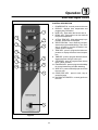
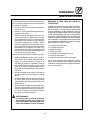
Solid State Digital Control
2
3
4
5
6
8
7
10
9
12
11
1
13
Figure 4
CONTROL DESCRIPTION
1. POWER SWITCH - controls power to the oven
2. D I SPLAY - displays time, temperature and
programming information
3. HEAT LED - lights when the burners are on
4. READY LED - lights when oven has reached
the preset t emperature
5. ACTUAL TEMP LED - lights when temp key is
pressed, actual temp is displayed
6. SELECTION D IAL - use to enter time, temper-
ature and programmable settings. Turn clock-
wise to increase or counter-clockwise to de-
crease values in display.
7. TEMP KEY - press to program the bake tem-
perature or display the actual oven tempera-
ture
8. TIME KEY - press t o program the bake time or
display the time during a bake cycle
9. STEAM KEY - press to program steam time to
inject a burst of steam
10. FAN DELAY KEY - press to program a time delay
for fan and heat during and after steaming
11. VENT KEY - press to manually open and close
the oven vent
12. START/STOP KEY - press to start, stop or
pause the bake
13. GAS SHUTOFF SWITCH - controls gas flow to
the oven

Operation
14
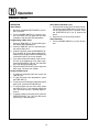
Standard Control
OPERATION
Oven Startup
1. Be sure the GAS SHUTOFF SWITCH (13) is in
the on position.
2. Tu rn the POWER SWITCH (1) to the on posi-
tion. The HEAT LED (3) lights and the oven
preheats to the last used set temperature.
Programming a Bake Cycle
1. Press the TEMP KEY (7). Turn the DIAL (6) to
the desired bake temperature.
2. Press the TIME KEY (8). Turn the DIAL (6) to
the desired bake time.
3. If steam is desired, press the STEAM KEY (9).
Turn the DIAL (6) to the desired steam time.
Steam may be programmed for the beginning
ofthebakecycleforuptotwominutes.
4. Ifyouwishtodelaytherotationoftheconvec-
tion fan at the beginning of the bake cycle,
press the FAN DELAY (10) key. Turn t h e DIA L
(6) to the desired fan delay time.
5. Press the START/STOP KEY (12) to begin the
bake cycle. The oven rack rotates.
DuringtheBakeCycle
1. To view the remaining bake time, press the
TIME KEY (8).
2. To view the actual oven temperature, press
the TEMP KEY (7).
3. To inject up to two minutes of steam during the
bake cycle, press the STEAM KEY (9).
4. To vent moisture from the oven cavity, press
the VENT KEY (11). This manually opens the
oven vent until the key is pressed again to
close it.
5. To pause a bake cycle at any point, press t he
START/STOP KEY (12). The cycle will pause
until the key is pressed again.
AttheEndoftheBakeCycle
1. Attheendofthebakecycle,analarmsounds,
the display reads DONE a nd the rack contin-
ues to rotate until the door is opened. Press
the START/STOP K EY (12) to silence the
alarm.
2. Open the door to remove the product.
Oven Shutdown
1. Turn the POWER SWITCH (1) to the off posi-
tion.

Operation
15
General Guidelines for Operating Personnel
BAKE TIMES AND TEMPERATURES
Preheating the oven
Always preheat the oven before baking or roast-
ing. We recommend preheating 50_F(10_C)
above the bake temperature to offset the drop in
temperature when the doors are opened and cold
product is loaded into the oven. Set the thermostat
to the bake temperature after the product is
loaded.
Bake Time
Check the product in about half the time recom-
mended for deck or range oven recipes. Record
times and temperatures which provide best re-
sults for future reference.
NOTE: Baketimewillvarywiththeamountof
product loaded, the type of pan and the
temperature.
OPERATING TIPS
Pans and Racks
Product or pan height determines how many
racks are used. The oven holds up to eight 18” x
24” (45.7 x 61 cm) bun pans with 4” rackspacing.
Load the oven from the bottom, centering t he pans
on the rack.
Roasting
To reduce shrinkage when roasting, place meat
directly on the racks. Place a sheet pan one-half
full of water in t he bottom rack position. The water
evaporates, increasing humidity in the oven
chamber. The pan catches grease from the meat,
making oven cleaning easier.
Fans
The fan must be operating for the oven to heat. To
avoid rippling of batter product use the following
procedure.
1. Preheat the oven 25_ F(15_C) above the bak-
ing temperature.
2. Loadtheovenwithproduct.Closethedoors.
3. Set the thermostat to the baking temperature.
4. Set the blower delay for two minutes.
Cool Down Mode
To facilitate cooling the oven to a lower tempera-
ture, press the TEMP KEY (7) and turn the DIAL (6)
to the left until the display reads COOL.

Maintenance
16
Cleaning and Preventative Maintenance
CLEANING THE OVEN
Stainless steel ovens may be kept clean and in
good condition with a light oil. Deposits of baked
on splatter, heat tint and heavy discoloration may
be removed with any non-toxic industrial stainless
steel cleaner.
1. Apply cleaners when the oven is cold. Always
rubwiththegrainofthemetal.
2. Dry the oven with a clean cloth.
Clean interior parts as follows:
1. Remove the rack from the oven.
2. Soak the parts in a s olution of ammonia and
water.
3. Reinstall after cleaning.
NOTE: If the oven is moved the restraint must be
reconnected after the unit is returned to it’s
regular position.
PREVENTATIVE MAINTENANCE
The best preventative maintenance measures are,
the proper installation of the equipment and a pro-
gram for routinely cleaning the ovens.
Annual Maintenance
This oven requires no lubrication. Maintenance
should be based on hours of usage. Refer to
OSHA specifications for maintenance intervals.
If maintenance or repairs are required, contact
your local Blodgett service company, a factory
representative or the Blodgett Oven company.
NOTE: All service functions can be reached from
the top of the oven or by removing the right
side body panel.
WARNING!!
Always disconnect the appliance from the
power supply before servicing or cleaning.
La page est en cours de chargement...
La page est en cours de chargement...
La page est en cours de chargement...
La page est en cours de chargement...
La page est en cours de chargement...
La page est en cours de chargement...
La page est en cours de chargement...
La page est en cours de chargement...
La page est en cours de chargement...
La page est en cours de chargement...
La page est en cours de chargement...
La page est en cours de chargement...
La page est en cours de chargement...
La page est en cours de chargement...
La page est en cours de chargement...
La page est en cours de chargement...
La page est en cours de chargement...
La page est en cours de chargement...
La page est en cours de chargement...
-
 1
1
-
 2
2
-
 3
3
-
 4
4
-
 5
5
-
 6
6
-
 7
7
-
 8
8
-
 9
9
-
 10
10
-
 11
11
-
 12
12
-
 13
13
-
 14
14
-
 15
15
-
 16
16
-
 17
17
-
 18
18
-
 19
19
-
 20
20
-
 21
21
-
 22
22
-
 23
23
-
 24
24
-
 25
25
-
 26
26
-
 27
27
-
 28
28
-
 29
29
-
 30
30
-
 31
31
-
 32
32
-
 33
33
-
 34
34
-
 35
35
-
 36
36
-
 37
37
-
 38
38
-
 39
39


Blodgett Microwave Oven XR8-G Manuel utilisateur
- Catégorie
- Cuisinières
- Taper
- Manuel utilisateur
- Ce manuel convient également à
dans d''autres langues
Documents connexes
-
Blodgett XR8-E Le manuel du propriétaire
-
-
-
Blodgett SG3240G Mode d'emploi
-
Blodgett RE Series Manuel utilisateur
-
-
-
-
-
Blodgett DFG-50 Manuel utilisateur
Autres documents
-
 Nu-Vu Food Service System OP-3/9M Fiche technique
-
GYS DRY ELECTRODES OVEN 10.350R (10kg - 50/350°C) Fiche technique
-
-
Equipex EP800 Le manuel du propriétaire
-
-
Baxter PW, RPW Le manuel du propriétaire
-
-
