Marshalltown 29592 Spin Screed Gas Powered Unit Manuel utilisateur
- Taper
- Manuel utilisateur

SPIN SCREED® GAS UNIT
Part #SPNRSSAGAS | EDI #29592
104 S. 8th Ave. | Marshalltown, IA
Phone 800-888-0127 / 641-753-0127 | Fax 800-477-6341 / 641-753-6341
www.MARSHALLTOWN.com
WS2860revC

2 of 12 104 S. 8th Ave. Marshalltown, IA Phone 800-888-0127 / 641-753-0127 • Fax 800-477-6341 / 641-753-6341 www.MARSHALLTOWN.com WS2860revC
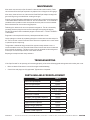
INTRODUCTION
Thank you for purchasing the Spin Screed®. The Spin Screed® is a simple and effective tool to screed concrete. Its simplicity
allows even the most inexperienced operators to screed effectively and accurately.
Specifications:
Part#: SPNRSSAGAS
EDI: 29592
Dimensions:
Power Head length: 49⁄" Dead End T-Handle length: 61⁄"
Power Head width: 11⁄" Dead End T-Handle width: 14⁄"
Live End diameter: 1⁄" Dead End T-Handle diameter: 1"
Live End length: 5" Dead End Pipe Adapter length: 4"
Live End Pipe Adapter diameter: 3.98"
Engine: Honda GX35, 35CC 4 Stroke Gasoline
Spin Screed® Pipe is sold separately. Specification of the 4" Schedule 40 seamless aluminum Spin Screed® Pipe:
Diameter: 4⁄ "
Thickness: ⁄ "
TABLE OF CONTENTS
SAFETY PRECAUTIONS .................................................................................................................................................................................3
WARRANTY ......................................................................................................................................................................................................4
ASSEMBLY GUIDE .......................................................................................................................................................................................5-6
PRODUCT OPERATION ...............................................................................................................................................................................7-8
MAINTENANCE ................................................................................................................................................................................................ 9
TROUBLESHOOTING ...................................................................................................................................................................................... 9
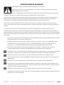
SIGNAL WORDS
UNDERSTAND SIGNAL WORDS
A signal word — DANGER, WARNING, or CAUTION — is used with the safety-alert system symbol. DANGER
identifies the most serious hazards.
DANGER!
• DANGER or
WARNING!
WARNING safety signs are located near specific hazards.
CAUTION!
• General precautions are listed on CAUTION safety signs.

3 of 12
104 S. 8th Ave. Marshalltown, IA Phone 800-888-0127 / 641-753-0127 • Fax 800-477-6341 / 641-753-6341 www.MARSHALLTOWN.comWS2860revC
SAFETY PRECAUTIONS
IMPORTANT — READ THIS MANUAL BEFORE ASSEMBLING OR OPERATING
After referring to the operation manual, if you still require assistance, please contact our customer
service department.
This operator’s manual has been prepared to provide the information you need to correctly operate and
maintain your unit. Read it carefully and keep it for future reference.
The replacement of any part on this product by other than the manufacturer’s authorized replacement part may adversely
affect the performance, durability, or safety of this product. Should you ever require repair parts or service, contact your
authorized parts and service dealer.
The manufacturer reserves the right to make changes or add improvements to its product at any time without prior notice.
The manufacturer also reserves the right to decide, upon its discretion at any time, to discontinue a product.
Read and follow all safety precautions and operating instructions in this manual.
Familiarity and proper training are required for the safe operation of this equipment. Equipment operated improperly or
by untrained personnel can damage equipment or cause bodily harm. Read the operating instructions contained in this
manual to familiarize yourself with the location and proper use of all the controls.
• DO NOT operate this machine until you have read the operating and safety instructions. ALWAYS operate the
machine in accordance with the manufacturer’s instructions.
• ALWAYS inspect your Spin Screed® upon arrival for damage or tampering that can rarely occur during shipping. If
damage is found, file a claim with your carrier immediately! Mark corresponding delivery receipt as “damaged
shipment”.
• NEVER allow untrained personnel to operate your Spin Screed®. Individuals who operate this screed should have
adequate training in operating procedures.
• CALIFORNIA PROPOSITION 65 WARNING: This product can expose you to chemicals known to the State of California
to cause cancer, birth defects, or other reproductive harm.
• NEVER use over-the-counter hardware to replace manufacturers’ hardware. Contact MARSHALLTOWN Customer
Service Department for information regarding replacement parts: 800-888-0127.
• DO NOT attempt to clean or service screed while machine is running.
• DO NOT use gasoline, other fuels, or any flammable solvent to clean parts, especially in enclosed areas. Fumes from
fuels and solvents can cause serious health problems if you are exposed to them over an extended period.
• ALWAYS wear adequate hearing protection while running your Spin Screed®.
• Refer to the included engine manufacturer’s manual for specific electrical requirements and safety information.
CAUTION!
CAUTION!
CAUTION!
CAUTION!
DANGER!

4 of 12 104 S. 8th Ave. Marshalltown, IA Phone 800-888-0127 / 641-753-0127 • Fax 800-477-6341 / 641-753-6341 www.MARSHALLTOWN.com WS2860revC
WARRANTY
This product is warranted to the original purchaser only, to be free of defects in material and workmanship under normal
use, for one year from purchase date. MARSHALLTOWN shall without charge for parts and labor, repair or replace such
parts which are found to be defective. All transportation charges for replacement parts must be borne by the purchaser.
For warranty service, the product must be delivered, with proof of purchase date, to MARSHALLTOWN. Contact
MARSHALLTOWN Customer Service to determine the best method of delivering the product that is under warranty. The
delivery of the product must be made no later than 30 days after the expiration of the warranty period.
If difficulty is encountered in having warranty work performed, contact 800-888-0127.
All implied warranties, including those of merchantability and fitness for a particular purpose, are limited to one year from
date of purchase by the original retail customer and to the extent permitted by law any and all implied warranties are
excluded and disclaimed after the expiration of such period.
Some states do not allow limitations on how long an implied warranty lasts, or the exclusion or limitations of incidental or
consequential damages, so the above limitations or exclusions may not apply to you. This warranty gives you specific legal
rights, and you may also have other rights, which vary from state to state.
Exclusion from this warranty:
1. All consequential damages, including pickup and delivery of the unit, communication, mileage charges and/or rental of
a replacement unit during repairs are not covered under this warranty, or are any loss of income and/or other loss resulting
from the failure of the product to function due to a warranty defect.
2. This warranty will not apply when the product becomes inoperative due to misuse, normal wear, neglect, improper
maintenance, accident or freight damage; has not been operated and maintained in accordance with the instructions
furnished in the Operator’s Manual; or has been altered or modified without approval from the factory Service
Department.
No parts or products are to be returned to the factory without prior written approval from the factory.

5 of 12
104 S. 8th Ave. Marshalltown, IA Phone 800-888-0127 / 641-753-0127 • Fax 800-477-6341 / 641-753-6341 www.MARSHALLTOWN.comWS2860revC
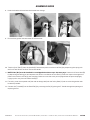
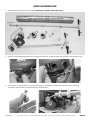
ASSEMBLY GUIDE
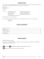
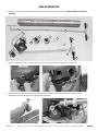
1. Lay out all the components of the Spin Screed® Assembly. Note: Pipe sold separately
B
A
K
C
J I
HE
D
D
Hole on end E
Pipe Sold Separately — Several Available Lengths
F
2. Squeeze the buckle release to open the filter cover and access the throttle connection point.
G
3. Ensure that the throttle adjuster is threaded onto the throttle cable (G) end and hook the cable end into the
throttle linkage.

6 of 12 104 S. 8th Ave. Marshalltown, IA Phone 800-888-0127 / 641-753-0127 • Fax 800-477-6341 / 641-753-6341 www.MARSHALLTOWN.com WS2860revC
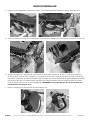
ASSEMBLY GUIDE
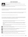
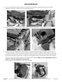
4. Swivel the throttle adjuster into the adjustment bracket, with the jam nut on one side and the full-sized nut
on the other.
5. Tighten the nuts to secure the throttle adjustment bracket then close the air filter cover.
6. Attach handle bar (A) to end of shaft using (2x) ⁄"-18 UNC x 2" LONG HHCS, washers and nuts (included). Prior to
tightening the handle bar on the end of the shaft, select right- or left-handed throttle lever position by flipping handle
bar over and adjust the balance of the handle bar (left to right) to achieve best handling for the specific application.
Attach both parts of the Dead-End T-Handle (D) and screw in the handle components (E). NOTE: It is best to have
the hole at the end perpendicular to the T-Handle.
7. Remove the cover and gasket from the throttle lever.

7 of 12
104 S. 8th Ave. Marshalltown, IA Phone 800-888-0127 / 641-753-0127 • Fax 800-477-6341 / 641-753-6341 www.MARSHALLTOWN.comWS2860revC
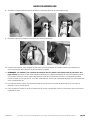
ASSEMBLY GUIDE
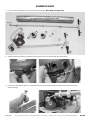
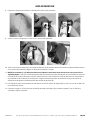
8. Hook the throttle cable end into the throttle lever linkage.
9. Re-Install the gasket and cover onto the throttle lever.
10. Take the Small Tool (F) from the Handle (A). Remove the power axle from Live End (J) by depressing the spring with
the Small Tool. Return the Small Tool to the Handle.
11. NOTE: Ends (I&J) must be installed in screed pipe before these steps. See next page. Connect the Power Head (B)
by depressing the locking pin on the power axle which is installed in the Live End (J). Insert the square drive lug on the
power axle into the Live End (J) pivot coupling. Check to assure the catch pin has popped into the pivot coupling by
trying to pull it away from the Power Head (B).
12. For safety, cover the exposed axle (the side not being used) with the Safety Boot (C) and attach to the gearbox with
hardware provided.
13. Connect the T-Handle (D) to the Dead End (I) by removing the Pin (H), placing the T-Handle through the opening and
replacing the Pin.

8 of 12 104 S. 8th Ave. Marshalltown, IA Phone 800-888-0127 / 641-753-0127 • Fax 800-477-6341 / 641-753-6341 www.MARSHALLTOWN.com WS2860revC
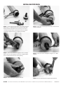
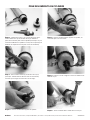
INSTALLING PIPE ENDS
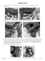
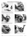
Step 1 – You’ll need: 12" Pipe Wrench, 9" Chain Clamp Vice
Grip, and a ⁄" Allen Wrench. Use the Chain Clamp Vice
Grip to hold the Pipe (Note: Do not attempt to or have a
co-worker hold the Pipe. You will not be able to produce
enough the torque necessary to tighten the Ends).
Step 4 – Insert set screw and tighten using the ⁄" Allen
Wrench.
Step 3 – Use the Pipe Wrench to tighten the Live End (J)
(Note: the Live End should be secured very tightly). Make
sure it is lined up with the set screw opening.
Step 2 – Insert the Live End (J) into the Pipe, make sure set
screw is removed.
Step 6 - Use the Pipe Wrench to tighten the Dead End.
Step 5 – Insert the Dead End (I) into the Pipe.

9 of 12
104 S. 8th Ave. Marshalltown, IA Phone 800-888-0127 / 641-753-0127 • Fax 800-477-6341 / 641-753-6341 www.MARSHALLTOWN.comWS2860revC
PRODUCT OPERATION
BEFORE STARTING
Before starting the Spin Screed®, there are a few items that need to be checked to prevent damage or personal injury.
• Affix safety boot (C) to unused side of screed power unit to cover rotating axle. Uncovered rotating axle may entangle
footgear, causing injury.
• Make sure that both Ends (I&J) are securely fastened to the end of the Pipe.
• Check all threaded connections to make sure that they are not loose.
• Check handles (D&E) to make sure that they will not loosen or detach during the operation of the Spin Screed®.
ENGINE MAINTENANCE RECOMMENDATIONS
Replace oil in engine with Honda #08209-10W30 oil after first 20 hours of operation. Replace again after next 40 hours of
operation. Using Honda #08209-10W30 product will prevent overfilling the engine. Failure to replace oil will dramatically
reduce engine life. See GX35 engine user's manual for operation of engine choke for cold startup and further maintenance
recommendations.
OPERATION
Operating your Spin Screed® correctly will assist you in achieving the desired outcome of a pour. Follow the instructions
below to operate your screed correctly.
• Start engine. Refer to Honda GX35 owners manual for basic starting instructions.
• Engage the power unit and begin to pull the Spin Screed® over forms, screed pipe, or screed rail, distributing the
concrete aggregate to the desired level. Make sure the Pipe is spinning away from you.
• The Spin Screed® is meant to run at a slow speed.
• Each operator must properly maintain control of both handles, guiding the Pipe over the concrete aggregate at a
speed and direction best suited for the aggregate’s respective slump.
• DO NOT allow either end of the unit to enter wet concrete. Keep each end on the forms, screed pipes, or screed rails
to prevent contamination of the plugs or motor.
• If the concrete is not being added at the appropriate rate, slow the screed down to compensate.
• The speed at which the screed should be pulled back and forth depends on the slump of the concrete (see slump
guidelines below). It is important to pay close attention to the aggregates, slump, and concrete modifying agents to
compensate the speed of the engine adequately.
• Do not allow the Spin Screed® to run in the same position for an extended period. If screeding is delayed, turn the
engine off and let the Spin Screed® sit in a position where it is best suited to start again. When the placement of
aggregate resumes, slowly engage the engine and continue screeding.
SLUMP GUIDELINES
The Spin Screed® will handle stiff concrete having only a 3-inch slump. When you first start using the Spin Screed®, pour
with a slump level that is consistent with your past practices. As with any new tool, certain operation techniques must be
learned.

10 of 12 104 S. 8th Ave. Marshalltown, IA Phone 800-888-0127 / 641-753-0127 • Fax 800-477-6341 / 641-753-6341 www.MARSHALLTOWN.com WS2860revC
PRODUCT OPERATION
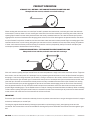
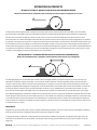
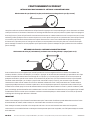
STRAIGHT PULL METHOD - WET CONCRETE OPERATING METHOD ONE
Slump levels of 5 or more, maintain 1 to 2 inch surcharge
When working with wet concrete, start the Spin Screed®, squeeze the throttle lever, and slowly pull it over the concrete
while muckers maintain about a 2-inch surcharge of concrete in front of the screed. After advancing 6 to 8 feet, allow the
spinning Spin Screed® to move slowly backward over the freshly screeded concrete. This slow backwards pass pushes
aggregate left on the surface down while bringing paste to the surface. After backing over the poured section, slow down
the Spin Screed® and pull the screed back to the area where more concrete has been placed. Begin screeding again. With
concrete wetter than a 5-inch slump, pulling over the concrete surface a second time with the motor running will produce
a flatter surface with sufficient paste for floating. Examine the surfaces prepared by the Spin Screed® and adjust your
technique to product the desired surface for floating.
BUMP AND RUN METHOD - STIFF CONCRETE OPERATING METHOD TWO
Slump levels of 3 to 4 inches, maintain 2.5 to 3.5 inch surcharge
With stiff concrete, pulling the Spin Screed® over the concrete produces a rough surface that is difficult to float. To get the
best results, use the “bump and run” technique. Start by squeezing the throttle lever to start the Spin Screed® and gently
bumping a 2-3-inch surcharge with the Spin Screed®, causing it to advance a few inches, and then allow it to retreat 4 to 6
inches. Advance the Spin Screed® again. Continue the “bump and run” technique until you have advanced 6 to 8 feet, then
allow the Spin Screed® to move backward slowly over the freshly screeded concrete with the Spin Screed® still running.
This slow backwards pass pushes aggregate left on the surface down while bringing paste to the surface. After backing
over the poured section, turn off the Spin Screed® and pull the screed back to the area where more concrete has been
placed. Begin screeding again. The screeded section is ready for floating and should be done immediately. When screeding
stiffer concrete, pulling the Spin Screed® forward a second time tends to remove the layer of paste that has been worked
to the surface and makes the surface more difficult to float and finish.
IMPORTANT
Ensure the Spin Screed® is cleaned immediately after use to prevent concrete from curing in the engine drive shaft, engine
enclosure, handle joints, or on the Pipe.
Cleaning the engine should be done by blowing compressed air and washing by hand—avoid getting water near the
carburetor. Pressure washers are recommended for cleaning the Pipe but should NOT be used to clean the engine or gear
box.
Spin Screed Techniques of Operation:
The Spin Screed power head has been designed with a reversing switch. The power head can be made to operate on
either side of the pour moving in either direction.
As with any electric tool, proper operating voltage is essential. Always use heavy-duty properly grounded extension
cords and follow the directions associated with the spin motor for maximum length and gauge of extension cords.
The spin motor draws 10 amperes of current at 120 volts when fully loaded. A portable electric generator can easily
provide this voltage and current requirement if a source of 120 volt AC is not otherwise available. GFI breakers are an
OSHA requirement for tools used on the construction site. All extension cords and power cords should be inspected
and tested for defects before being placed into operations. Defective cords not protected by GFI breakers could lead
to death or severe injury.
The Spin Screed will handle stiff concrete having only a 3-inch slump or any larger slump that you choose to pour. We
advise that when you rst start using the Spin Screed, you pour with a slump level that is consistent with your past
practices. As with any new tool you bring onto your job site, certain techniques of operation must be learned so the
quality level of work you demand can be achieved.
With wet concrete, you will probably nd that the spin motor can be energized and the Spin Screed slowly pulled over
the concrete while muckers are maintaining about a two-inch surcharge of concrete in front of the screed. Once you
have advanced for 6 to 8 feet or more, you will want to allow the Spin Screed to move backward slowly over the freshly
screeded concrete while the Spin Screed is still spinning. This slow backward pass pushes any concrete aggregate
that may be above the surface down into the surface while at the same time bringing paste to the surface. Once you
have backed over the section just poured, you will want to turn off the spin motor and simply pull the screed back to
the area where more concrete has been placed and begin the screeding operation again. With concrete wetter than a
5 inch slump, you may nd that pulling over the concrete surface a second time, while the spin motor is still running,
will produce a atter surface with sufcient paste for bull oating. The general rule is to examine the surface prepared
by the Spin Screed and adjust your screeding technique to produce the most desirable surface for bull oating.
1-888-329-6039 • www.spinscreed.com
Wet Concrete
Operating Method No. 1:
Slump levels of 5 inches
or more. Maintain 1 to 2
inch surcharge.
Stiff Concrete
Operating Method
No. 2:
Slump levels of 3 to
4 inches. Maintain
2.5 inch to 3.5 inch
surcharge.
STRAIGHT PULL
BUMP AND RUN
(OVER)

11 of 12
104 S. 8th Ave. Marshalltown, IA Phone 800-888-0127 / 641-753-0127 • Fax 800-477-6341 / 641-753-6341 www.MARSHALLTOWN.comWS2860revC
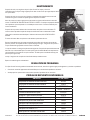
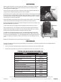
MAINTENANCE
After each use, ensure the Spin Screed® is cleaned and stored carefully. Find a
secure location for the Pipe to prevent any objects from falling on or damaging it.
After every three to four uses, lubricate the Dead End Pipe Adapter through the
grease fitting using a standard lever-action grease gun.
Prior to starting the engine, add engine oil at the fill port at the base of the engine.
THE ENGINE WAS SHIPPED WITHOUT OIL IN THE CRANKCASE. A small bottle is
included with the product which corresponds with the precise amount needed.
Retain the bottle for future measuring purposes.
Following first 20 hours of run time replace the engine oil. The oil is drained by
removing the drain plug from the base of the engine and tipping the engine.
Fill only the amount recommended by engine manufacturer — DO NOT OVERFILL
THE ENGINE.
Engine oil is to be replaced after every subsequent 40 hours of use.
Check sponge air cleaner by squeezing the plastic intake cover catches and pull it
off. The air cleaner can be rinsed with water. Be sure to squeeze out as much water
as possible prior to replacing.
The gearbox is delivered fully greased. After approximately 40 hours use it is
recommended that the user inject NLGI #0 Lithium Grease into the zerk mounted
on the side of the gearbox. The drain screw must be removed to allow old grease
to escape. Be sure to replace drain screw when finished.
Repeat grease replacement every 40 hours.
TROUBLESHOOTING
If the Spin Screed® is not spinning or functioning properly, refer to the following guide to diagnose and resolve your issue.
• Refer to Honda GX35 owner's manual for engine troubleshooting.
• Check if the end plugs are fully tightened. Tighten them if required.
ITEM PART#
Dead End Pipe Adapter SPNDE
Live End Pipe Adapter SPNLE
Power Head* SPNRSSGAS
Pipe** SPNP4 – SPNP22
Quick Disconnect Pin SPNQDP
Dead End T Handle SPNDH
Gearbox, Gas Screed, Replace 29588
Throttle Lever Replace 29589
Engine Switch Replace 29590
Axle Assembly Replace 29591
PTO Cover Replace 29593
Throttle Cable Replace 29594
*Handle & Motor enclosure with Power Head **Pipe available from 4’ to 22’ in even numbers
PARTS AVAILABLE FOR REPLACEMENT
Zerk
Drain
Drain
Plug

104 S. 8th Ave., Marshalltown, IA
Phone 800-888-0127 / 641-753-0127
Fax 800-477-6341 / 64 1-753-6341
www.MARSHALLTOWN.com
WS2860revC

ENRASADORA SPIN SCREED® DE GASOLINA
N.º de pieza SPNRSSAGAS | N.º EDI 29592
104 S. 8th Ave. | Marshalltown, IA
Teléfono 800-888-0127 / 641-753-0127 | Fax 800-477-6341 / 641-753-6341
www.MARSHALLTOWN.com
WS2860revC

2 de 12 104 S. 8th Ave. Marshalltown, IA Teléfono 800-888-0127 / 641-753-0127 • Fax 800-477-6341 / 641-753-6341 www.MARSHALLTOWN.com WS2860revC
INTRODUCCIÓN
Gracias por su compra de la enrasadora Spin Screed®. La Spin Screed® es una herramienta simple y eficaz para enrasar
hormigón. Su simplicidad permite que incluso los operadores sin experiencia enrasen de manera eficaz y precisa.
Especificaciones:
N.º de pieza: SPNRSSAGAS
EDI: 29592
Dimensiones:
Longitud del motor: 49⁄" (1267 mm) Longitud del mango en T para extremo cerrado: 61⁄" (1568 mm)
Ancho del motor: 11⁄" (292 mm) Ancho del mango en T para extremo cerrado: 14⁄" (368 mm)
Diámetro del extremo abierto: 1⁄" (32 mm) Diámetro del mango en T para extremo cerrado: 1" (25 mm)
Largo del extremo abierto: 5" (127 mm) Largo del adaptador de tubo del extremo cerrado: 4" (102 mm)
Diámetro del adaptador de tubo del extremo abierto: 3.98" (101 mm)
Motor: Honda GX35, 35CC de 4 tiempos a gasolina*
El tubo de la Spin Screed® se vende por separado. Especificación del tubo de la Spin Screed® de aluminio de una sola pieza,
cédula 40 de 4":
Diámetro: 4⁄ " (114 mm)
Espesor: ⁄ " (6.35 mm)
CONTENIDO
PRECAUCIONES DE SEGURIDAD ................................................................................................................................................................. 3
GARANTÍA ......................................................................................................................................................................................................... 4
GUÍA DE MONTAJE ...................................................................................................................................................................................... 5-6
OPERACIÓN DEL PRODUCTO ....................................................................................................................................................................7-8
MANTENIMIENTO ............................................................................................................................................................................................9
DIAGNÓSTICO DE FALLAS .............................................................................................................................................................................9
PALABRAS DE AVISO
ENTENDER LAS PALABRAS DE AVISO
Una palabra de aviso PELIGRO, ADVERTENCIA o PRECAUCIÓN se utiliza con el símbolo del sistema de alerta-
seguridad. PELIGRO identifica los riesgos más graves.
• Los letreros de seguridad PELIGRO o ADVERTENCIA se encuentran ubicados cerca de riesgos específicos.
• Las medidas de seguridad generales se enumeran en los letreros de seguridad de PRECAUCIÓN.
DANGER!
PELIGRO
DANGER!
ADVERTENCIA
DANGER!
PRECAUCIÓN

3 de 12
104 S. 8th Ave. Marshalltown, IA Teléfono 800-888-0127 / 641-753-0127 • Fax 800-477-6341 / 641-753-6341 www.MARSHALLTOWN.comWS2860revC
PRECAUCIONES DE SEGURIDAD
IMPORTANTE: LEA ESTE MANUAL ANTES DEL MONTAJE U OPERACIÓN
Después de consultar el manual de operación, si aún necesita asistencia, comuníquese con nuestro
departamento de servicio al cliente.
Este manual del operador se ha preparado para proporcionar la información que necesita para operar y
mantener correctamente su unidad. Léalo con atención y consérvelo para futuras consultas.
El reemplazo de cualquier pieza de este producto por una pieza de repuesto de cualquier otro fabricante puede afectar
negativamente el desempeño, durabilidad o seguridad de este producto. En caso de necesitar piezas de repuesto o
mantenimiento, comuníquese con su distribuidor autorizado de mantenimiento y piezas de repuesto.
El fabricante se reserva el derecho de hacer cambios o añadir mejoras a su producto cualquier momento y sin previo
aviso. El fabricante también se reserva el derecho a decidir, a su entera discreción en cualquier momento, descontinuar un
producto.
Lea y siga todas las instrucciones de operación y precauciones de seguridad que se encuentran en este manual.
Es necesario que se familiarice y reciba el entrenamiento correcto para poder operar este equipo de manera segura. Un
equipo operado incorrectamente o por un personal sin entrenamiento puede dañar el equipo y ocasionar daños personales.
Lea las instrucciones de operación contenidas en este manual para familiarizarse con la ubicación y el uso correcto de todos
los controles.
• NO opere esta máquina hasta que haya leído las instrucciones de operación y seguridad. SIEMPRE opere la máquina
de conformidad con las instrucciones del fabricante.
• SIEMPRE inspeccione la enrasadora Spin Screed® al recibirla a fin de buscar daños o alteraciones que pueden
presentarse en raras ocasiones durante el envío. Si se descubre algún daño, ¡presente inmediatamente una
reclamación a su transportista! Marque el recibo de entrega correspondiente como “envío dañado”.
• NUNCA permita que el personal sin entrenamiento opere la Spin Screed®. Las personas que operan esta
enrasadora deben recibir un entrenamiento adecuado sobre los procedimientos de la operación.
• ADVERTENCIA DE LA PROPUESTA 65 DE CALIFORNIA: Este producto puede exponerlo a químicos que en el estado
de California se conocen como causantes de cáncer, defectos de nacimiento u otros daños reproductivos.
• NUNCA utilice herrajes de venta libre para reemplazar los herrajes del fabricante. Comuníquese con el
Departamento de Servicio al Cliente de MARSHALLTOWN para obtener información sobre las piezas de repuesto:
800-888-0127.
• NO intente limpiar o dar mantenimiento a la enrasadora mientras la máquina está en funcionamiento.
• NO use gasolina, otros combustibles o cualquier solvente inflamable para limpiar piezas, especialmente en áreas
encerradas. Los vapores de los combustibles y solventes pueden ocasionar graves problemas de salud si usted es
expuesto a ellos por un periodo prolongado.
• SIEMPRE use la protección para los oídos apropiada mientras utiliza la enrasadora Spin Screed®.
• Consulte el manual del fabricante del motor que se incluye para obtener información sobre los requisitos eléctricos
específicos y los datos de seguridad.
DANGER!
PRECAUCIÓN
DANGER!
PRECAUCIÓN
DANGER!
PRECAUCIÓN
DANGER!
PRECAUCIÓN
DANGER!
PELIGRO

4 de 12 104 S. 8th Ave. Marshalltown, IA Teléfono 800-888-0127 / 641-753-0127 • Fax 800-477-6341 / 641-753-6341 www.MARSHALLTOWN.com WS2860revC
GARANTÍA
Este producto está garantizado solo al comprador original frente a defectos en material y mano de obra bajo un uso normal,
por un año a partir de la fecha de compra. MARSHALLTOWN reparará o reemplazará, sin cargo alguno por piezas y mano de
obra, dichas piezas que se determinen como defectuosas. Todos los cargos de transportación de las piezas de repuesto
deberán ser pagados por el comprador.
Para obtener el servicio de garantía, el producto debe ser enviado, con prueba de la fecha de compra, a MARSHALLTOWN.
Comuníquese con el servicio al cliente de MARSHALLTOWN para determinar el mejor método para enviar el producto que
está bajo la garantía. El producto debe enviarse a más tardar 30 días después del vencimiento del periodo de garantía.
Si tiene dificultades para que se efectúe un trabajo cubierto en la garantía, comuníquese al 800-888-0127.
Todas las garantías implícitas, incluyendo aquellas de comerciabilidad e idoneidad para una finalidad en especial, están
limitadas a un año a partir de la fecha de compra por parte el cliente minorista original y en la medida que lo permita la ley,
además se excluyen y se renuncia a todas las garantías implícitas después del vencimiento de dicho periodo.
Algunos estados no permiten limitaciones sobre la duración del periodo de una garantía implícita, o la exclusión o
limitaciones de daños indirectos o consecuentes, por lo que las limitaciones o exclusiones mencionadas pueden no aplicar
a su caso. Esta garantía le otorga derechos legales específicos y es posible que usted tenga otros derechos que varían de
estado a estado.
Exclusión de esta garantía:
1. Todos los daños consecuentes, incluyendo la recolección y entrega de la unidad, comunicación, cargos por kilometraje
y/o renta de una unidad de reemplazo durante reparaciones no están cubiertos por esta garantía ni tampoco cualquier
pérdida de ingresos y/u otras pérdidas que resulten por la falla de funcionamiento del producto debido a un defecto
cubierto por la garantía.
2. Esta garantía no aplicará cuando el producto se vuelva inoperativo debido al mal uso, desgaste normal, negligencia,
mantenimiento inadecuado, accidente o daño en el transporte; no ha sido operado y mantenido de conformidad con
las instrucciones proporcionadas en el manual del operador o ha sido alterado o modificado sin la aprobación del
Departamento de Servicio de la fábrica.
Ninguna pieza o producto debe regresarse a la fábrica sin la aprobación previa por escrito de la fábrica.

5 de 12
104 S. 8th Ave. Marshalltown, IA Teléfono 800-888-0127 / 641-753-0127 • Fax 800-477-6341 / 641-753-6341 www.MARSHALLTOWN.comWS2860revC
GUÍA DE MONTAJE
1. Ponga a la vista todos los componentes del conjunto de la enrasadora Spin Screed®. Nota: El tubo se vende por
separado
B
A
K
C
J I
HE
D
D
Orificio en el extremo E
El tubo se vende por separado (disponible en varias longitudes)
F
2. Apriete la hebilla para abrir la cubierta del filtro y tener acceso al punto de conexión del acelerador.
G
3. Asegúrese de que el ajustador del acelerador esté enroscado en el extremo del cable del acelerador (G) y
enganche el extremo del cable en la conexión del acelerador.

6 de 12 104 S. 8th Ave. Marshalltown, IA Teléfono 800-888-0127 / 641-753-0127 • Fax 800-477-6341 / 641-753-6341 www.MARSHALLTOWN.com WS2860revC
GUÍA DE MONTAJE
4. Use un movimiento giratorio para introducir el ajustador del acelerador al soporte de ajuste con la tuerca de
seguridad en un lado y la tuerca de tamaño completo en el otro.
5. Apriete las tuercas para fijar el soporte de ajuste del acelerador, luego cierre la cubierta del filtro de aire.
6. Coloque la barra del mango (A) en el extremo del eje usando (2x) tornillos de cabeza hexagonal 5/16"-18 UNC x 2"
DE LARGO, arandelas y tuercas (se incluyen). Antes de apretar la barra del mango en el extremo del eje, seleccione
la posición de la palanca del acelerador a la derecha o izquierda girando el mango y ajuste el equilibrio del mango (de
izquierda a derecha) para lograr el mejor manejo para la aplicación específica. Conecte ambas partes del mango en
T para el extremo cerrado (D) y atornille los componentes del mango (E). NOTA: Lo más recomendable es tener el
orificio en el extremo perpendicular al mango en T.
7. Retire la cubierta y el empaque de la palanca del acelerador.

7 de 12
104 S. 8th Ave. Marshalltown, IA Teléfono 800-888-0127 / 641-753-0127 • Fax 800-477-6341 / 641-753-6341 www.MARSHALLTOWN.comWS2860revC
GUÍA DE MONTAJE
8. Enganche el extremo del cable en la conexión de la palanca del acelerador.
9. Vuelva a instalar el empaque y la cubierta en la palanca del acelerador.
10. Tome la herramienta pequeña (F) del mango (A). Retire el eje de potencia del extremo abierto (J) presionando el resorte
con la herramienta pequeña. Regrese la herramienta pequeña al mango.
11. NOTA: Los extremos (I y J) deben instalarse en el tubo de la enrasadora antes de efectuar estos pasos. Vea la
siguiente página. Conecte el cabezal de potencia (B) presionando el pasador de bloqueo en el eje de potencia que está
instalado en el extremo abierto (J). Inserte la orejeta de transmisión cuadrada en el eje de potencia en el acoplamiento
de pivote del extremo abierto (J). Verifique para asegurarse de que el pasador de retención se haya insertado en el
acoplamiento de pivote tratando de alejarlo del cabezal de potencia (B).
12. Por seguridad, cubra el eje expuesto (el lado que no se usa) con la bota de seguridad (C) y fíjela a la caja de cambios con
los accesorios provistos.
13. Conecte el mango en T (D) al extremo cerrado (I) quitando el pasador (H), pasando el mango en T por la abertura y
volviendo a colocar el pasador.

8 de 12 104 S. 8th Ave. Marshalltown, IA Teléfono 800-888-0127 / 641-753-0127 • Fax 800-477-6341 / 641-753-6341 www.MARSHALLTOWN.com WS2860revC
INSTALACIÓN DE LOS EXTREMOS DEL TUBO
Paso 1: necesitará lo siguiente: Llave de tubo de 12", alicate de
sujeción de cadena de 9" y llave Allen de ⁄". Use el alicate de sujeción
de cadena para sostener el tubo (Nota: No intente sostener el tubo
usted mismo ni le pida que lo haga a un compañero de trabajo. No
podrá producir el par de torsión necesario para apretar los extremos).
Paso 4: inserte el tornillo de fijación y apriételo usando la llave Allen
de ⁄".
Paso 3: use la llave de tubo para apretar el extremo abierto (J)
(Nota: El extremo abierto debe quedar muy apretado). Asegúrese
de que quede alineado con la abertura del tornillo de fijación.
Paso 2: inserte el extremo abierto (J) en el tubo, asegurándose de
que el tornillo de fijación no esté presente.
Paso 6: use la llave de tubo para apretar el extremo cerrado.
Paso 5: inserte el extremo cerrado (I) en el tubo.
La page est en cours de chargement...
La page est en cours de chargement...
La page est en cours de chargement...
La page est en cours de chargement...
La page est en cours de chargement...
La page est en cours de chargement...
La page est en cours de chargement...
La page est en cours de chargement...
La page est en cours de chargement...
La page est en cours de chargement...
La page est en cours de chargement...
La page est en cours de chargement...
La page est en cours de chargement...
La page est en cours de chargement...
La page est en cours de chargement...
La page est en cours de chargement...
-
 1
1
-
 2
2
-
 3
3
-
 4
4
-
 5
5
-
 6
6
-
 7
7
-
 8
8
-
 9
9
-
 10
10
-
 11
11
-
 12
12
-
 13
13
-
 14
14
-
 15
15
-
 16
16
-
 17
17
-
 18
18
-
 19
19
-
 20
20
-
 21
21
-
 22
22
-
 23
23
-
 24
24
-
 25
25
-
 26
26
-
 27
27
-
 28
28
-
 29
29
-
 30
30
-
 31
31
-
 32
32
-
 33
33
-
 34
34
-
 35
35
-
 36
36


Marshalltown 29592 Spin Screed Gas Powered Unit Manuel utilisateur
- Taper
- Manuel utilisateur
dans d''autres langues
Documents connexes
-
Marshalltown Speed Striker 2.0 Le manuel du propriétaire
-
-
-
Marshalltown TC24 Manuel utilisateur
-
-
-
Autres documents
-
Wal-Board Tools WAL-BOARD TOOLS 051-007 Pro Manuel utilisateur
-
 Marshalltown Company Enforcer E400 Manuel utilisateur
-
Wacker Neuson P35A Manuel utilisateur
-
-
-
Wacker Neuson P31A Parts Manual
-
Wacker Neuson P35A-X Parts Manual
-
Wacker Neuson P35A EU Parts Manual
