
608
2 x 300 Watt Powered Mixer
MANUEL DE L'UTILISATEUR
OWNER'S MANUAL
TYPE: YS1088
0
5
28
7
6
4
3
91
10
0
5
28
7
6
4
3
91
10
MAIN
MON
Pan
Mon
EFX
GAIN
Lo
Mid
Hi
1
Bal
MON EFX Rtn
MAIN EFX Rtn
Power
Rec Out
Tape/CD
Post-EQ
MAIN OUT
MON OUT
Post-EQ
MON OUT
Rec OUT
Tape/CD IN
Footswitch
EFX OUT
Mic
Line Line
Mic
Line Line
MicMic Mic
Instrument
Hi/Z
Instrument
Hi/Z
Mic
1234
5/6 7/8
clip
Pan
Mon
EFX
GAIN
Lo
Mid
Hi
2
clip
Pan
Mon
EFX
GAIN
Lo
Mid
Hi
3
clip
Pan
Mon
Mon
EFX
EFX
GAIN GAIN
Lo
Lo
Mid
Hi
4
Hi
5/6
clip clip
Bal
Mon
EFX
GAIN
Lo
Hi
7/8
clip
Power AMP IN
AB
Lo Hi
EQUALIZER A
Lo Hi
EQUALIZER B
Mute 1-6
Amp
Assign
Main/Mon
Left /Right
0
10
-15+15
dB
-15+15
dB
-15+15
dB
0
5
28
7
6
4
3
91
10
0
5
28
7
6
4
3
91
10
0
5
28
7
6
4
3
91
10
0
5
28
7
6
4
3
91
10
0
5
28
7
6
4
3
91
10
0
5
28
7
6
4
3
91
10
0
5
28
7
6
4
3
91
10
0
5
28
7
6
4
3
91
10
0
5
28
7
6
4
3
91
10
0
5
28
7
6
4
3
91
10
+15
+10
+5
0
-5
-10
-15
160 250 400 630 1.0K 1.6K 2.5K 4.0K 6.3K
-15+15 -15+15
+15
+10
+5
0
-5
-10
-15
160 250 400 630 1.0K 1.6K 2.5K 4.0K 6.3K
-15+15
-15+15
0
10
-15+15
dB
-15+15
dB
-15+15
dB
0
5
28
7
6
4
3
91
10
0
10
-15+15
dB
-15+15
dB
-15+15
dB
0
5
28
7
6
4
3
91
10
0
10
0
10
0
10
-15+15
dB
-15+15
dB
-15+15
dB
-15+15
dB
-15+15
dB
0
5
28
7
6
4
3
91
10
-15 +15
dB
-15 +15
dB
0
5
28
7
6
4
3
91
10
0
5
28
7
6
4
3
91
10
0
5
28
7
6
4
3
91
10
608
2 x 300 Watt Powered Mixer
S TEREO S TEREO
48V Phantom Power
M
O
D
U
L
A
T
I
O
N
G
A
T
E
H
A
R
D
I
S
T
P
L
A
T
E
S
E
C
H
O
H
A
L
L
S
R
O
O
M
clip
EFX
clip clip
Modify
24
+
-
16
1
15
214
313
412
511
610
79
8

The exclamation point within an equilatereal triangle is
intended to alert the user to the presence of important
operating and maintenance (servicing) instructions in
the literature accompanying the appliance.
Le point d’exclamation à l’intérieur d’un triangle équilatéral
est prévu pour alerter l’utilisateur de la présence
d’instructions importantes dans la littérature accompag-
nant l’appareil en ce qui concerne l’opération et la
maintenance de cet appareil.
This lightning flash with arrowhead symbol, within
an equilateral triangle, is intended to alert the user to
the presence of uninsulated “dangerous voltage”
within the product’s enclosure that may be of sufficient
magnitude to constitute a risk of electric shock to persons.
Ce symbole d’éclair avec tête de flèche dans un triangle
équilatéral est prévu pour alerter l’utilisateur de la présence d’un
« voltage dangereux » non-isolé à proximité de l’enceinte du
produit qui pourrait être d’ampleur suffisante pour présenter
un risque de choque électrique.
IMPORTANT SAFETY INSTRUCTIONS
safety-4v7 • May 7/2008
CAUTION: TO REDUCE THE RISK OF ELECTRIC
SHOCK, DO NOT REMOVE COVER (OR BACK).
NO USER SERVICEABLE PARTS INSIDE.
REFER SERVICING TO QUALIFIED
SERVICE PERSONNEL.
FOLLOW ALL INSTRUCTIONS SUIVEZ TOUTES LES INSTRUCTIONS
Instructions pertaining to a risk of fire,
electric shock, or injury to a person
Read Instructions: The Owner’s Manual should be read and understood before operation
of your unit. Please, save these instructions for future reference and heed all warnings.
Clean only with dry cloth.
Packaging: Keep the box and packaging materials, in case the unit needs to be
returned for service.
Warning: To reduce the risk or fire or electric shock, do not expose this apparatus to rain or
moisture. Do not use this apparatus near water!
Warning: When using electric products, basic precautions should always be followed,
including the following:
Power Sources
Your unit should be connected to a power source only of the voltage specified in the
owners manual or as marked on the unit. This unit has a polarized plug. Do not use
with an extension cord or receptacle unless the plug can be fully inserted. Precau-
tions should be taken so that the grounding scheme on the unit is not defeated. An
apparatus with CLASS I construction shall be connected to a Mains socket outlet with
a protective earthing ground. Where the MAINS plug or an appliance coupler is used
as the disconnect device, the disconnect device shall remain readily operable.
Hazards
Do not place this product on an unstable cart, stand, tripod, bracket or table. The
product may fall, causing serious personal injury and serious damage to the product.
Use only with cart, stand, tripod, bracket, or table recommended by the manufacturer
or sold with the product. Follow the manufacturer’s instructions when installing the
product and use mounting accessories recommended by the manufacturer. Only use
attachments/accessories specified by the manufacturer
Note: Prolonged use of headphones at a high volume may cause
health damage on your ears.
The apparatus should not be exposed to dripping or splashing water; no objects
filled with liquids should be placed on the apparatus.
Terminals marked with the “lightning bolt” are hazardous live; the external wiring
connected to these terminals require installation by an instructed person or the use of
ready made leads or cords.
Ensure that proper ventilation is provided around the appliance. Do not install near
any heat sources such as radiators, heat registers, stoves, or other apparatus
(including amplifiers) that produce heat.
No naked flame sources, such as lighted candles, should be placed on the apparatus.
Power Cord
Do not defeat the safety purpose of the polarized or grounding-type plug. A polarized plug
has two blades with one wider than the other. A grounding type plug has two blades and a
third grounding prong. The wide blade or the third prong are provided for your safety. If the
provided plug does not fit into your outlet, consult an electrician for replacement of the
obsolete outlet. The AC supply cord should be routed so that it is unlikely that it will be
damaged. Protect the power cord from being walked on or pinched particularly at plugs. If
the AC supply cord is damaged DO NOT OPERATE THE UNIT. To completely disconnect
this apparatus from the AC Mains, disconnect the power supply cord plug from the AC
receptacle. The mains plug of the power supply cord shall remain readily operable.
Unplug this apparatus during lightning storms or when unused for long periods of time.
Service
The unit should be serviced only by qualified service personnel. Servicing is required
when the apparatus has been damaged in any way, such as power-supply cord or plug is
damaged, liquid has been spilled or objects have fallen into the apparatus, the apparatus
has been exposed to rain or moisture, does not operate normally, or has been dropped.
AVIS: AFIN DE REDUIRE LES RISQUE DE CHOC
ELECTRIQUE, N’ENLEVEZ PAS LE COUVERT (OU LE
PANNEAU ARRIERE) NE CONTIENT AUCUNE PIECE
REPARABLE PAR L’UTILISATEUR.
CONSULTEZ UN TECHNICIEN QUALIFIE
POUR L’ENTRETIENT
Instructions relatives au risque de feu,
choc électrique, ou blessures aux personnes
Veuillez Lire le Manuel: Il contient des informations qui devraient êtres comprises avant
l’opération de votre appareil. Conser
vez. Gardez S.V.P. ces instructions pour consultations
ultérieures et observez tous les avertissements.
Nettoyez seulement avec le tissu sec.
Emballage: Conservez la boite au cas ou l’appareil devait être retourner pour réparation.
Avertissement: Pour réduire le risque de feu ou la décharge électrique, n'exposez pas
cet appareil à la pluie ou à l'humidité. N’utilisez pas cet appareil près de l’eau!
Attention: Lors de l’utilisation de produits électrique, assurez-vous d’adhérer à des
précautions de bases incluant celle qui suivent:
Alimentation
L’ appareil ne doit être branché qu’à une source d’alimentation correspondant au
voltage spécifié dans le manuel ou tel qu’indiqué sur l’appareil. Cet appareil est équipé
d’une prise d’alimentation polarisée. Ne pas utiliser cet appareil avec un cordon de
raccordement à moins qu’il soit possible d’insérer complètement les trois lames. Des
précautions doivent êtres prises afin d’eviter que le système de mise à la terre de
l’appareil ne soit désengagé. Un appareil construit selon les normes de CLASS I
devrait être raccordé à une prise murale d’alimentation avec connexion intacte de mise
à la masse. Lorsqu’une prise de branchement ou un coupleur d'appareils est utilisée
comme dispositif de débranchement, ce dispositif de débranchement devra demeurer
pleinement fonctionnel avec raccordement à la masse.
Risque
Ne pas placer cet appareil sur un chariot, un support, un trépied ou une table instables.
L’appareil pourrait tomber et blesser quelqu’un ou subir des dommages importants.
Utiliser seulement un chariot, un support, un trépied ou une table recommandés par le
fabricant ou vendus avec le produit. Suivre les instructions du fabricant pour installer
l’appareil et utiliser les accessoires recommandés par le fabricant. Utilisez seulement
les attachements/accessoires indiqués par le fabricant
Note: L'utilisation prolongée des écouteurs à un volume élevé peut
avoir des conséquences néfastes sur la santé sur vos oreilles. .
Il convient de ne pas placer sur l’appareil de sources de flammes nues, telles que
des bougies allumées.
L’appeil ne doit pas être exposé à des égouttements d’eau ou des éclaboussures
et qu’aucun objet rempli de liquide tel que des vases ne doit être placé sur l’appareil.
Assurez que lappareil est fourni de la propre ventilation. Ne procédez pas à
l’installation près de source de chaleur tels que radiateurs, registre de chaleur, fours
ou autres appareils (incluant les amplificateurs) qui produisent de la chaleur.
Les dispositifs marqués d’une symbole “d’éclair” sont des parties dangereuses
au toucher et que les câblages extérieurs connectés à ces dispositifs de
connection extérieure doivent être effectivés par un opérateur formé ou en utilisant
des cordons déjà préparés.
Cordon d’Alimentation
Ne pas enlever le dispositif de sécurité sur la prise polarisée ou la prise avec tige de
mise à la masse du cordon d’alimentation. Une prise polarisée dispose de deux lames
dont une plus large que l’autre. Une prise avec tige de mise à la masse dispose de
deux lames en plus d’une troisième tige qui connecte à la masse. La lame plus large ou
la tige de mise à la masse est prévu pour votre sécurité. La prise murale est désuète si
elle n’est pas conçue pour accepter ce type de prise avec dispositif de sécurité. Dans
ce cas, contactez un électricien pour faire remplacer la prise murale. Évitez
d’endommager le cordon d’alimentation. Protégez le cordon d’alimentation. Assurez-
vous qu’on ne marche pas dessus et qu’on ne le pince pas en particulier aux prises.
N’UTILISEZ PAS L’APPAREIL si le cordon d’alimentation est endommagé. Pour
débrancher complètement cet appareil de l’alimentation CA principale, déconnectez le
cordon d’alimentation de la prise d’alimentation murale. Le cordon d’alimentation du
bloc d’alimentation de l’appareil doit demeurer pleinement fonctionnel.
Débranchez cet appareil durant les orages ou si inutilisé pendant de longues périodes.
Service
Consultez un technicien qualifié pour l’entretien de votre appareil. L'entretien est
nécessaire quand l'appareil a été endommagé de quelque façon que se soit. Par exemple
si le cordon d’alimentation ou la prise du cordon sont endommagés, si il y a eu du liquide
qui a été renversé à l’intérieur ou des objets sont tombés dans l'appareil, si l'appareil a été
exposé à la pluie ou à l'humidité, si il ne fonctionne pas normalement, ou a été échappé.
S2125A

1
MICROMI
X
Introduction
Thank you for purchasing a Yorkville powered mixer. We at Yorkville Sound are con-
fident that you’ll find the M608 to be an excellent and versatile mixer/amp. We’ve
used our experience in the development of powered mixers to create the smallest,
lightest, and most powerful combination mixer/amplifiers available. This manual
contains information to help you get the maximum performance from your M608. We
hope you’ll take the time to read it.
Stereo Power Amplifier
The M608 features high-efficiency stereo power amplifiers that have been designed to deliv-
er maximum power into 4 to 8 ohm loads. When lower speaker impedances are connected,
a dedicated, sonically transparent circuit limits the output power to safe levels. Multiple
speakers may be connected without the amplifier overheating or shutting down.
Input Channels
1. MIC and LINE Inputs
The M608 features gold-plated, dual-contact
XLR low-impedance microphone connectors on
the channels. These microphone inputs are bal-
anced for maximum noise suppression. Condenser
microphones can also be connected. The 48 Volt
DC phantom power is activated by depressing the
Phantom Power push-button on the rear panel.
Note: Condenser and dynamic mics can be used together while the phantom
power is on. It will not affect the performance of the dynamic mics.
0
10
-15 +15
dB
-15 +15
dB
-15 +15
dB
0
5
28
7
6
4
3
91
10
0
5
28
7
6
4
3
91
10
0
5
28
7
6
4
3
91
10
0
5
28
7
6
4
3
91
10
0
5
28
7
6
4
3
91
10
0
5
28
7
6
4
3
91
10
0
5
28
7
6
4
3
91
10
0
5
28
7
6
4
3
91
10
0
5
28
7
6
4
3
91
10
0
5
28
7
6
4
3
91
10
+15
+10
+5
0
-5
-10
-15
160 250 400 630 1.0K 1.6K 2.5K 4.0K 6.3K
-15 +15 -15 +15
+15
+10
+5
0
-5
-10
-15
160 250 400 630 1.0K 1.6K 2.5K 4.0K 6.3K
-15 +15
-15 +15
0
10
-15 +15
dB
-15 +15
dB
-15 +15
dB
0
5
28
7
6
4
3
91
10
0
10
-15 +15
dB
-15 +15
dB
-15 +15
dB
0
5
28
7
6
4
3
91
10
0
10
0
10
0
10
-15 +15
dB
-15 +15
dB
-15 +15
dB
-15 +15
dB
-15 +15
dB
0
5
28
7
6
4
3
91
10
-15 +15
dB
-15 +15
dB
0
5
28
7
6
4
3
91
10
0
5
28
7
6
4
3
91
10 0
5
28
7
6
4
3
91
10
608
2 x 300 Watt Powered Mixer
Pan
Mon
EFX
GAIN
Lo
Mid
Hi
1
Bal
MON EFX Rtn
MAIN EFX Rtn
Power
Rec Out
Tape/CD
Post-EQ
MAIN OUT
MON OUT
Post-EQ
MON OUT
Rec OUT
Tape/CD IN
Footswitch
EFX OUT
Mic
Line Line
Mic
Line Line
Mic Mic Mic
Instrument
Hi/Z
Instrument
Hi/Z
Mic
1234
5/6 7/8
clip
Pan
Mon
EFX
GAIN
Lo
Mid
Hi
2
clip
Pan
Mon
EFX
GAIN
Lo
Mid
Hi
3
clip
Pan
Mon
Mon
EFX
EFX
GAIN GAIN
Lo
Lo
Mid
Hi
4
Hi
5/6
clip clip
Bal
Mon
EFX
GAIN
Lo
Hi
7/8
clip
Power AMP IN
AB
Lo Hi
EQUALIZER A
Lo Hi
EQUALIZER B
Mute 1-6
Amp
Assign
Main/Mon
Left /Right
STEREO STEREO
48V Phantom Power
1/4-inch Phone Plug
1/4-inch T.R.S. Phone Plug
XLR Plug
Mic
Line Line
Mic Mic
Instrument
Hi/Z
14
5/6

2
MICROMI
X
In addition to the XLR inputs, each channel features ¼-inch LINE in jacks. Channels
1-2, 5/6 and 7/8 are balanced line-level inputs and will accept either balanced (Tip/
Ring/Sleeve) or unbalanced (Tip/Sleeve) input cables from high impedance microphones,
mixer line outputs, keyboards, synthesizers, electric pianos etc.
Note: When connecting a balanced signal, use balanced patch cables with either an
XLR or a Tip/Ring/Sleeve ¼-inch plug on the mixer end.
Channels 3 and 4 have very high impedance, unbalanced ¼-inch inputs which are opti-
mized for instruments such as electric basses, acoustic electric guitars etc. Stereo chan-
nels 5/6 and 7/8 have left and right ¼-inch balanced LINE in jacks as well as mono gold-
plated XLR low impedance microphone inputs. The ¼-inch inputs may be used to connect
a stereo CD player, tape deck or an additional mixer etc. A phono pre-amplifier must be
connected to the M608 inputs for optimum turntable performance.
Connecting signals to both types of inputs on any one channel (MIC and LINE in) is
not recommended. To do so may change the gain of the input circuit.
Note: You may connect a stereo source to channels 1 through 6 but you must
use two channels, one for left and one for right and Pan appropriately or sum to
mono using a ‘Y’ cable.
2. Channel GAIN Controls and CLIP LEDs
This adjustment determines the signal level sent to the MAIN mixing bus. The CLIP LED
will illuminate when the channel’s overall signal level is 3 dB below the onset of actual
clipping. As a result, small amounts of clip LED activity are acceptable, however frequent
or continuous activity indicates the need to turn down the GAIN control.
In audio terminology, a bus is a mix-down channel where all the signals from the
input channels are blended into one signal. The M608 has 5 busses: MAIN (left and
right), MONITOR, EFFECTS and RECORD OUT.
3. Channel Lo, Mid, and Hi Equalization
The M608 tone controls adjust the bass, middle and treble frequencies for each channel
independently. Center frequencies have been carefully selected to help achieve the best
quality of sound. Bass is centered on 40 Hz, Mid at 700 Hz and the Hi is at 12 kHz. The
adjustment range for each control is +/- 15 dB. These parameters provide versatile equal-
ization consistent with the clean simplicity of the M608’s design. As with equalizers,
boosting one or more frequencies increase the channel’s level. If the channel is already at
a high level, clipping may occur, in which case the clip LED will illuminate. Reduce the
GAIN setting and/or the Equalizer if clip activity is excessive.
Note: The center position reflects a neutral or flat EQ control setting; however, turn-
ing down EQ settings can be used effectively to reduce feedback and/or distortion).
4. Channel MON Controls
The MON control (monitor send) on each channel varies the amount of signal being
sent to the monitor bus in the M608. In the mono channels the MON signal is pre-
GAIN control and pre-EQ. It is taken before the GAIN control so the monitor signal can
be mixed independently of the MAIN mix. As a result, channel EQ and GAIN settings
do not affect the sound of the monitor signals. The MON signal in the stereo channels
is also pre-GAIN and pre-EQ.
Note: With an independent monitor mix, it may be beneficial to connect a graphic
equalizer between the MON output and the monitor amplifier (Power AMP IN B,
external amplifier or powered speakers, depending on how you have it set up) to
help control feedback.
5. Channel EFX Controls
The EFX control (effects send) for each channel adjusts the level of the channel signal
being sent to the M608 effects bus. This signal is post-GAIN control and post-EQ, the
sound is affected by both the channel EQ controls and the channel GAIN control. The sig-
nal from the effects bus is internally routed to the Digital Effects Processor. The channel
EFX control regulates the intensity of the built-in digital effects for the channel’s output.
When using the built-in digital effects, you can connect a standard on/off footswitch (e.g.
Yorkville model AFS1) to the EFX Out/Footswitch jack to turn the internal effects on or off.
For more information see the section EFX Out/Footswitch in this manual.
0
5
28
7
6
4
3
91
10
0
10
-15 +15
dB
-15 +15
dB
-15 +15
dB
0
5
28
7
6
4
3
91
10
Pan
Mon
EFX
GAIN
Lo
Mid
Hi
1
clip

3
MICROMI
X
Tip: Alternatively, this signal at this jack can be connected to the input of an exter-
nal stereo effects unit and returned via channel 5/6 or 7/8 However, if you do not
require any effects at all, the effects bus output signal can be connected to the
input of an additional monitor system or another amp/speaker system via the EFX
Out/Footswitch jack using a standard balanced patch cord. In this case, the EFX
controls would act as send controls to achieve a semi-separate mix. Remember
that the channel GAIN controls also affect this signal.
6. Channel Pan and Bal Controls
The signal balance of each channel going to the left and right main PA channels can be
adjusted by the Pan control in channels 1 to 4, and by the Bal control in channels 5/6
and 7/8. Turning this control counterclockwise towards the L will increase the signal level
in the left channel to a maximum of 3 dB while also reducing the GAIN in the right chan-
nel to zero. Turning the control clockwise towards the R will increase the signal GAIN in
the right channel while also reducing the signal GAIN in the left channel.
Master Section
1. MAIN Master Control
The MAIN master control adjusts the overall level of the main
mix, the PA volume.
Note: To ensure maximum signal headroom and clarity, set
the channel GAIN controls first for a good signal without clip-
ping, then set the master for the overall volume desired.
2. MON Master Control
The overall level of the monitor mix is adjusted with the MON
master control.
Note: As with the MAIN master, set the MON
master to deliver the desired volume after set-
ting the channel sends.
3. MAIN EFFECTS Return Control
The MAIN EFX control regulates the amount of signal going
from the output of the internal Digital Effects Processor to
the MAIN mixing bus where it is mixed with the dry signals
directly. It controls the intensity of the effects on the left
and right MAIN output signals.
4. MON EFFECTS Return Control
The MON EFX control regulates the amount of signal going
from the output of the internal Digital Effects Processor to
the MON mixing bus where it is mixed with the dry signals
directly from the channel MON send controls. It controls the
overall effects intensity for the MON Out signal.
5. Post-EQ OUT
These jacks offer a variety of patching and routing options. They are positioned in the
signal path after the M608 main graphic equalizers.
These bus signals are at line level, not speaker level (use the SPEAKER outputs on
the rear panel to drive speakers). Using signals from these jacks has no effect on the
operation of the M608's built-in power amplifier. This makes it possible to feed an
external power amplifier, or even multiple inter-connected power amps, while the inter-
nal power amplifier is functioning.
Note: It is not necessary to have speakers connected if you’d like to use the unit
strictly as a mixer. If a mono signal is required, possibly to feed a mono-house PA or
another amp/speaker system, use the L/Mono Post-EQ jack. Mono operation of this
jack is switched to left channel only as soon as a jack is inserted in the L Post-EQ
jack. They follow the operation of the Main/Mon switch described below.
0
5
28
7
6
4
3
91
10
0
5
28
7
6
4
3
91
10
MON EFX Rtn
MAIN EFX Rtn
Post-EQ
MAIN OUT
Post-EQ
MON OUT

4
MICROMI
X
6. Power AMP IN Jacks
The Power AMP A IN and Power AMP B IN jacks
are direct inputs to the built-in power amplifiers.
They are referred to as A and B rather than left
and right simply because it is possible to power
both main PA speakers with one amplifier channel
and monitors with the other. This can be accom-
plished by selecting the Main/Mon position on
the selector switch located between the graphic
equalizers. In the Left/Right position, Power AMP A receives the left signal while Power
AMP B receives the right signal. In the Main/Mon position, Power AMP A receives a mono
sum of left and right signals while Power AMP B receives the monitor signal. An alternative
use for the Power AMP A IN and Power AMP B IN jacks would be as patching inputs. Since
they’re switching jacks if you plug into one (or both) the internal signal flow will be inter-
rupted. This interrupts the signal from the M608 mixer to the built-in power amplifiers allow-
ing you to insert signal control devices such as an élite processor, an additional equalizer,
or a compressor/limiter into the main stereo signal path. Connect cables from the L and R
Post-EQ OUT to the device’s input jacks and then from the device’s output jacks to the M608
Power AMP A IN and Power AMP B IN jacks.
You can connect another mixer to the M608 power amplifier through the Power AMP A IN
and Power AMP B IN jacks. This slaves the amplifier to the other mixer’s signals; it no longer
receives the built-in mixer’s signals which means that you could use the built-in mixer to do a
totally separate mixing job. For example, you could patch the M608 L and R Post-EQ OUT to
inputs on another mixer connected to other amplifiers driving a PA speaker system while using
the M608’s A and B amps to power control room speakers.
7. Rec OUT Jacks
These phono connectors send the L and R pre-EQ, pre-EFFECTS (not affected by the
MAIN EQ) main mix signals. The Rec OUT control adjusts the signal level for these
jacks. Using phono patch cords, connect directly to the Auxiliary (line-level) inputs on a
tape deck or other recording device.
8. MON Out Jack
The monitor bus output signal from the Mon OUT jack is line level
and would normally be patched to the input of a mono power ampli-
fier (or a single channel of a stereo amp) driving stage monitor speak-
ers. Keep in mind that in the Left/Right position of the Amp Assign
switch there is no internal equalization for the monitor mix (you
might want to patch a graphic equalizer between the Mon OUT jack
and the input of your monitor power amplifier, this can help regulate
the feed). As mentioned under #4. Post-EQ OUT section (above), the
monitor mix signal can also be patched to one channel of the internal
amplifier using the Amp Assign switch.
9. EFX Out / Footswitch Jack
Using this jack you can connect a standard on/off footswitch to
control the activation of the internal Digital Effects Processor or
it can be used as an effects send jack for use with an external
effects processor.
Note: Both devices would be sent a signal, so you could connect the external unit’s
left and right outputs to the L and R inputs on channel 5/6 (channel 7/8 or any of
the other channels). Use the GAIN of that channel to adjust the amount of wet
signal added to the main mix and the MON control to adjust the amount of wet sig-
nal added to the monitor mix. Make sure that its EFX control on the channels are
turned off. An alternative would be to use the EFX Out / Footswitch jack to deliver
line level signal to the input of an auxiliary amplifier or even a recording device.
Here, the channel EFX controls would act as secondary level controls.
Rec OUT
Tape/CD IN
Power AMP IN
AB
MON OUT
Footswitch
EFX OUT

5
MICROMI
X
10. Power LED and Switch
The Power LED lets you know that the M608 is plugged in, turned on and all systems
are normal. The AC power on/off switch is on the rear panel of the M608.
11. Phantom Power
The Phantom Power LED indicates that 48 volts of DC phantom power is present on
the XLR microphone inputs for powering condenser microphones. Regular dynamic mics
may also be used while the Phantom Power is on. Connecting a microphone of either
type with phantom power on and the channel GAIN up will create a large transient,
resulting in a loud, potentially damaging pop. When setting up, either turn off the AC
power, the phantom power, or set all channel levels to zero. The Phantom Power push-
button is located on the rear panel between the speaker output jacks.
12. Tape/CD Input
Left and right RCA inputs are provided to connect a CD player, cassette player or other
stereo source to the mixer. These inputs are routed directly to the main bus, the Tape/CD
control adjusts the amount of signal.
13. Mute 1-6 Switch
The M608 includes a feature that enables users to instantly mute channels 1-6. Depressing
the Mute 1-6 switch will mute channels 1-6 signals being sent to the Left, Right, Mon and
EFX busses (the signals from these channels will still be sent to the record bus and will not
be muted. Channel 7/8 will remain active, leaving this channel open for allowing a micro-
phone or CD player, cassette player or other stereo source to be heard over the Left, Right,
Mon and EFX busses. This feature lets you mute the mics and instruments on stage and
still allows you to make announcements or play music during breaks. When the band returns
to perform, simply disable the mute.
Note: The Tape/CD input in the master section also remains active. While muted, the
Mute LED flashes at a slow rate (long on/short off) and the clip LEDs of all the muted
channels alternate long off/short on.
14. Amp Assign Switch
The MAIN controls determine the level of the signal routed through the Amp Assign switch:
i. In the Left/Right position, the Amp Assign switch directs the left and right MAIN
master signals through Equalizer A and Equalizer B. The signal goes to the left
and right inputs of the built-in power amplifier (Amp A and Amp B) and to the
left and right post-EQ OUT jacks.
ii. In the Main/Mon position, the Amp Assign switch sums the left and right
MAIN signals into a single, mono signal while directing it to the input of
Equalizer A, the output of which goes to both the Amp A power amp channel
and to the Post-EQ MAIN OUT jack. Additionally, the signal from the MON mas-
ter’s output is routed through Equalizer B and then to both the Amp B power
amp channel and to the MON Out jack.
Digital Effects Processor
1. Select and MODIFY EFX Controls
Use the EFX Selection control to choose from the
sixteen 24-bit digital reverbs, delays and other
effects. This control rotates continuously, which lets
you rotate clockwise or counter-clockwise to select
the desired effect. For convenience, a table of the
effects and their variables appear later in this manu-
al and on the front panel of the M608.
Parameters for each of the effects can be changed using the MODIFY control which is
located next to the Selection control. For example, if a Hall reverb has been selected,
the MODIFY control will let you adjust the decay parameter. Choosing the Chorus effect
allows the chorus rate to be adjusted.
0
5
28
7
6
4
3
91
10
0
5
28
7
6
4
3
91
10
Rec Out
Tape/CD
Rec OUT
Tape/CD IN
Amp
Assign
Main/Mon
Left /Right

6
MICROMI
X
Note: The signal sent from the internal Digital Effects Processor to the MON mix is
independent from the MON send controls on the channel strips. When a channel’s
EFX control routes a signal to the internal Effects processor and the MON level con-
trol (for that channel) is turned off, the channel’s wet effects will still be audible in the
monitor bus (if the EFX to MONitor return level is turned up).
2. Effects CLIP LED
Situated to the right of the MODIFY EFX control, the CLIP LED indicates that the digi-
tal processor is receiving an input signal that’s too strong, resulting in distortion. For
optimum performance, the CLIP LED should never flash. If there is clipping activity, turn
down the channel EFX controls appropriately.
Built in 9-Band Graphic Equalizer & Shelving EQs
1. General
Each EQ consists of a set of +/-15dB range type controls. In the M608 there are nine
sliders for each channel, each one operating over a 2/3-octave portion of the midrange
band of sound frequencies, as well as rotary shelving Bass and Treble controls.
Note: Equalizers have an effect on the gain of the main system as well as its fre-
quency response. Once adjusted, you may need to adjust the MAIN master level if
the clip LEDs become too active.
2. Main Functions for the Graphic EQ and Shelving Equalizers
i. To adjust the system to help reduce feedback, a normal technique is to turn the
main system up to the point of feedback and then adjust the EQ sliders individu-
ally to determine which frequency band will reduce the potential of feedback.
When the specific frequency band is isolated, set it to about -3 to -5 dB. Usually
only 2 or 3 bands can be reduced before the feedback reduction process begins
to affect the sound quality.
Room Reverb
Hall Reverb
Hall Reverb - Vocals
Hall Reverb w/Echo
Plate Reverb
Plate Reverb - Vocals
Plate Reverb w/Echo
Gated Reverb
decay
decay
decay
decay
ModifyEffect
decay
gain
pitch
delay
rate
1.
2.
3.
4.
5.
6.
7.
8.
9.
10.
11.
12.
13.
14.
15.
16.
Fast Echo
Short Decay Echo
Long Decay Echo
Chorus
Flanger
Rotary Speaker
Distortion
Harmonizer
ModifyEffect
+15
+10
+5
0
-5
-10
-15
160 250 400 630 1.0K 1.6K 2.5K 4.0K 6.3K
-15 +15 -15 +15
+15
+10
+5
0
-5
-10
-15
160 250 400 630 1.0K 1.6K 2.5K 4.0K 6.3K
-15 +15
-15 +15
Lo Hi
EQUALIZER A
Lo Hi
EQUALIZER B

7
MICROMI
X
ii. To adjust for deficiencies in the speaker system’s high frequency and bass response,
the M608 also has a 2-band rotary shelving equalizer. These work in conjunction with
the 9-band graphic. Yorkville engineers have developed this technique to provide
you with greater tone shaping capability. This allows the graphic equalizer bands fre-
quencies to be spaced at closer intervals, which mean better selectivity for feedback
reduction and sound shaping. You may want to turn up the Lo and Hi controls to
give the system a more HiFi sound when you’re playing at lower volumes. At higher
volume levels, you may need to turn these controls down, this will help maximize
the volume and tighten up the sound.
iii. The third use of the graphic equalizer is to adjust the sound character for artistic
reasons. The frequencies are adjusted until the sound feels best to the musicians.
M608 Rear Panel
1. Power Amplifiers
Each of the M608 dual power amplifiers has two ¼-inch jacks and 1 Speakon jack for
speaker connections. The power amplifiers are designed to provide full power into a 4 to
8-ohm load. Connecting two 4-ohm speakers (2-ohm load) to either AMP A or AMP B will
not harm the M608 but the maximum power output may be slightly reduced.
WARNING: Do not obstruct the flow of air around the vents on the rear of the M608,
this may cause the power amplifier to overheat. The amplifier will start to reduce its
power output in order to keep running. In extreme cases it may be forced to shut
down. After the M608 cools down, operation will be restored automatically This con-
dition should not occur if adequate ventilation is provided at the back of the unit.
2. Power Switch and Breaker
The Power switch and circuit breaker are located on the rear panel. If the circuit breaker
trips during use, wait a few minutes (to cool), then push in to reset. The circuit breaker
can trip if the amplifier is too heavily loaded with long periods of continuous tones (such
as feedback). If the circuit breaker trips immediately after being reset, take the unit to
your Yorkville dealer for service.
CHANNEL
B
CHANNEL
A
SPEAKER OUTPUT SPEAKER OUTPUT
Phantom
Power
SPEAKON™ Pin
Configuration
1+/1–
on off
250 Watts
MAX
250 Watts
MAX
POWER
ON
Circuit
Breaker
DESIGNED & MANUFACTURED BY YORKVILLE SOUND • TORONTO, CANADA
MODEL TYPE: YS1088
A-Z1340 / 1.0
DISCONNECT POWER
BEFORE SERVICING!
DEBRANCHER L’APPEREIL
AVANT D’ENLEVER
LES COUVERCLES!
THIS UNIT MUST BE GROUNDED!
CET APPAREIL DOIT ETRE MIS Á TERRE!
608
2 x 300 Watt Powered Mixer
4080001

8
MICROMI
X
General Operating Instructions
1. Connect the AC power cord to a 120 Volt AC grounded power outlet (220 to 240 Volts
in export units).
2. Turn the MAIN and MON master controls to 0 initially, then switch on the Power.
3. You can connect low-impedance microphones to the 3-pin XLR type MIC inputs.
4. Connect high-impedance mics or mono line-level signal sources (mixer line outputs,
keyboards etc.), to the ¼-inch balanced LINE IN jacks on channels 1-2, 5/6 and 7/8.
Connecting more than one signal source to both XLR and ¼-inch inputs is not recom-
mended; this includes stereo sources (if you try to connect a stereo source to a mono
channel using a Y-adapter, you may get distortion). The ¼-inch channels 3 and 4 are
optimized for musical instruments and are not balanced.
5. Connect stereo sources (CD players, tape decks, stereo keyboards etc.) to chan-
nels 5/6 or 7/8 via the stereo ¼-inch balanced LINE IN type inputs. Once again,
connect only one signal source per channel, and use shielded patch cords for all
pre-amp connections. If a monitor send or EFX send is not required use the Tape/CD
input for your stereo source.
6a. Use 18-gauge (or heavier) speaker cables, using shielded patch cords to connect speakers
will waste power by heating up. Connect one or two 8-ohm PA speakers to the SPEAKER
outputs on the rear panel.
Note: To deliver maximum power to a pair of 4-ohm PA speakers, connect only one
speaker to each amplifier.
6b. If you are using a separate power amplifier for the stage monitor speakers, connect
the main speakers (as in #6, above) and run a shielded patch cord from the Post-
EQ Mon Out jack to the input of the monitor power amp. If you are using a sepa-
rate graphic equalizer for the monitors run a shielded patch cord from the Mon Out
jack to the input of the EQ. Then, another one from the EQ’s output to the input of
the monitor power amp.
7. Position your main PA speakers at the front of the stage, pointing directly at the audi-
ence. Position your monitor speakers on the stage floor; preferably to one side of the
mic stands, pointing up at the performer. Try to use cardioid or uni-directional mics to
help reduce the threat of feedback through the monitors (avoid having the back of the
mic pointing directly at the speakers).
8. During a sound check and with the band playing, make the following control adjustments:
i. On mono channels, you can use the GAIN control to set the channel volume level.
ii. Set the channel Lo, Mid, and Hi EQ controls at center. Set the channel GAIN, MON,
and EFX controls to seven. The Graphic EQ sliders and rotary shelving controls
should be set at the center position at this point as well.
iii. Turn the MAIN and MON Master controls up to give the desired volume, the MAIN
EFX return to around 7. Effects in the monitors tend to increase the possibility of
feedback so if the band insists, set the MON EFX return to 5.
iv. Adjust the channel MON control/s to give each performer the desired volume levels.
Use the MON master control to adjust the overall monitor level.
v. Use the channel GAIN control/s to balance each channel’s volume level through the
main PA speakers.
vi. Turn up the EFX controls on those channels requiring the selected Digital Effect. Typically,
the lead and harmony vocal channels would be good candidates for effects. Reverb can be
used on other channels or on recorded music, but should be used sparingly.
Keep the Main Speakers
between mics and audience
to minimize feedback
DO NOT place Main
Speakers in back of
the stage!!

9
MICROMI
X
9. Feedback during a performance is usually caused by one of the stage monitors. The
main PA is less likely to feedback because the mics are usually a good distance from
the main PA speakers. Therefore, if you’re using monitors, and feedback occurs, try
the following procedures:
i. Turn the MON Master down until the feedback stops.
ii. If a graphic equalizer is patched between the MON output and your monitor power
amp, adjust the EQ sliders individually to determine which frequency band will reduce
the potential of feedback.
iii. Now turn the MON Master back up. If the feedback returns, reset the sliders to
their original positions and retry using different sliders.
iv. In the rare case of main system feedback, follow the above type of procedure, but
use the MAIN Master and the built in Graphic EQ.
Input Wiring tips:
1. For all input connectivity use shielded wire only. Cables with a foil shield or a high-
density braid are best.
2. When changing input connections, turn down the level controls on the mixer to
eliminate pops and thumps out of the loudspeakers as the cable contacts the mixer.
3. Keep input connection cables as short as possible to minimize noise and hum.
1/4-inch T.R.S.
Phone Plug
Balanced 1/4-inch T.R.S. to Balanced XLR
XLR Plug
(Male)
Tip = 0°
Ring = 180°
Sleeve = Ground
1
Pin 1 = Ground
Pin 2 = 0°
Pin 3 = 180°
2
3

10
MICROMI
X
Introduction
Merci de vous être procurer un mixeur amplifié de Yorkville. Nous sommes certains que votre
nouvel M608 sera un excellent et polyvalent mixeur/amplificateur. Nous avons jumelé notre
expérience dans le développement et production de mixeurs amplifiés avec notre système
informatique à la fine pointe de la technologie afin de créer le plus petit, le plus léger, et
le plus puissant mixeur /amplificateur disponible. Ce manuel contient l’information néces-
saire qui vous permettra d ’obtenir de votre M608 la meilleure performance possible. Nous
espérons que vous prendrez quelques instants pour vous familiariser avec son contenu.
Amplificateur de Puissance Stéréo
Le M608 est muni d’un amplificateur de puissance stéréo à haute efficacité qui a été conçu
pour offrir une puissance maximale dans une charge de 4 à 8 ohms. Lorsqu’une charge de
haut-parleur plus basse y est connectée, un circuit offrant une performance acoustique trans-
parente limite la sortie à un niveau qui ne pause pas de risque. De multiples haut- parleurs
peuvent y être branchés sans causer une surchauffe ou éteindre l’appareil.
Canaux d’Entrées
1. Canaux Pour Microphone & Niveau Ligne
Le M608 est muni sur tous les canaux de con-
necteurs type XLR à double contact et plaqué or
pour microphone à basse impédance. Ces entrées
pour microphone sont électriquement équilibrées
pour obtenir une suppression maximum du bruit et
elles permettent aussi le raccordement de micro-
phone à condensateur. L’alimentation en duplex de
48 Volt DC est activé en appuyant sur le bouton poussoir situé au panneau arrière.
Note: les microphones à condensateur et les microphones dynamiques peuvent être
simultanément utilisés avec l’alimentation en duplex présente sur tout les canaux. La
performance des microphones dynamiques ne sera pas affectée.
0
10
-15 +15
dB
-15 +15
dB
-15 +15
dB
0
5
28
7
6
4
3
91
10
0
5
28
7
6
4
3
91
10
0
5
28
7
6
4
3
91
10
0
5
28
7
6
4
3
91
10
0
5
28
7
6
4
3
91
10
0
5
28
7
6
4
3
91
10
0
5
28
7
6
4
3
91
10
0
5
28
7
6
4
3
91
10
0
5
28
7
6
4
3
91
10
0
5
28
7
6
4
3
91
10
+15
+10
+5
0
-5
-10
-15
160 250 400 630 1.0K 1.6K 2.5K 4.0K 6.3K
-15 +15 -15 +15
+15
+10
+5
0
-5
-10
-15
160 250 400 630 1.0K 1.6K 2.5K 4.0K 6.3K
-15 +15
-15 +15
0
10
-15 +15
dB
-15 +15
dB
-15 +15
dB
0
5
28
7
6
4
3
91
10
0
10
-15 +15
dB
-15 +15
dB
-15 +15
dB
0
5
28
7
6
4
3
91
10
0
10
0
10
0
10
-15 +15
dB
-15 +15
dB
-15 +15
dB
-15 +15
dB
-15 +15
dB
0
5
28
7
6
4
3
91
10
-15 +15
dB
-15 +15
dB
0
5
28
7
6
4
3
91
10
0
5
28
7
6
4
3
91
10 0
5
28
7
6
4
3
91
10
608
2 x 300 Watt Powered Mixer
Pan
Mon
EFX
GAIN
Lo
Mid
Hi
1
Bal
MON EFX Rtn
MAIN EFX Rtn
Power
Rec Out
Tape/CD
Post-EQ
MAIN OUT
MON OUT
Post-EQ
MON OUT
Rec OUT
Tape/CD IN
Footswitch
EFX OUT
Mic
Line Line
Mic
Line Line
Mic Mic Mic
Instrument
Hi/Z
Instrument
Hi/Z
Mic
1234
5/6 7/8
clip
Pan
Mon
EFX
GAIN
Lo
Mid
Hi
2
clip
Pan
Mon
EFX
GAIN
Lo
Mid
Hi
3
clip
Pan
Mon
Mon
EFX
EFX
GAIN GAIN
Lo
Lo
Mid
Hi
4
Hi
5/6
clip clip
Bal
Mon
EFX
GAIN
Lo
Hi
7/8
clip
Power AMP IN
AB
Lo Hi
EQUALIZER A
Lo Hi
EQUALIZER B
Mute 1-6
Amp
Assign
Main/Mon
Left /Right
STEREO STEREO
48V Phantom Power
1/4-inch Phone Plug
1/4-inch T.R.S. Phone Plug
XLR Plug
Mic
Line Line
Mic Mic
Instrument
Hi/Z
14
5/6

11
MICROMI
X
En plus des prises XLR, chaque canal est muni de prise d’entrée LIGNE 1/4-pouce. Ces
entrées sur les canaux 1-2, 5/6 et 7/8 sont symétrique et acceptent les signaux symé-
triques (Pointe-Bague-Manchon) ou asymétriques (Pointe-Manchon) provenant de source
haute impédance telles celles de microphones, guitares, sortie ligne d’amplificateur, syn-
thétiseurs, pianos électriques, etc.
Note: quand vous reliez un signal symétrique, utilisez des câbles symétriques avec
prise XLR ou Pointe/Bague/Manchon (stéréo) 1/4-pouce à l’extrémité de mixeur.
L’impédance des entrées asymétriques ¼ de pouce des canaux 3 et 4 est très élevée.
Ces entrées sont optimisé pour des instruments tel basses électriques, guitares acous-
tiques avec micro etc. Les canaux stéréo 5/6 et 7/8 sont muni de prise d’entrée LIGNE
symétrique ¼-pouce de gauche et droite en plus de prise d’entrées XLR mono plaquée or
pour microphones à basses impédance. Les prises d’entrées ¼-pouce peuvent être utili-
sées pour le raccordement d’un lecteur CD stéréo, magnétophone à cassette ou mixeur
additionnel etc. Un préamplificateur phono doit être connecté aux entrées du M608 pour
obtenir une performance optimum lors de l’utilisation d’une platine.
Le raccordement de signaux aux deux types d’entrées sur n’importe quel canal (MIC
et LINE in) n’est pas recommandé. Ceci pourrait affecter le gain du circuit d’entrée.
Note: Vous pouvez raccorder une source stéréo aux canaux 1 à 6 mais pour ce faire
faire vous devez utiliser deux canaux, un pour le signal de gauche et un pour celui
de droite. Les commande Pan doivent être réglés selon le cas. Vous pouvez aussi
mélanger les signaux en un signal mono à l’aide d’un câble en ‘Y’.
2. Commandes GAIN de canal et DELs CLIP
Cette commande détermine le niveau du signal acheminé au bus de mélange PRINCIPAL.
La DEL CLIP est réglée de façon à s’illuminer lorsque le niveau de signal général de canal
est de 3dB en dessous du niveau réel d’écrêtage. Une légère activité des DEL est donc
acceptable. Une activité fréquente ou continue indique cependant qu’il est nécessaire de
réduire le niveau de la commande GAIN.
Dans la terminologie audio, un bus est un canal de mélange où les signaux de tous
les canaux d’entrée sont mélangé pour former un seul signal. Le M608 possède 5
bus, Principal (gauche et droite), Moniteurs, Effets et RECORD OUT.
3. Égalisation de Basse, Médianes et Aiguës de Canal
Les commandes de tonalité du M608 ajustent indépendamment les fréquences graves,
médianes et aiguës pour chaque canal. Les fréquences centrales ont été soigneusement
sélectionnés pour aider à atteindre la meilleure qualité de son. Les graves sont centrée
sur 40 Hz, les médianes à 700 Hz et les aiguës à 2 kHz. La gamme de réglage de gain
pour chaque contrôle est plus ou moins (+/-) 15dB fournissant une égalisation souple,
qui s’harmonise avec la simplicité du M608. Comme avec tout égalisateur, un renforce-
ment à une ou plusieurs fréquences produira une augmentation du niveau de signal du
canal. La DEL CLIP s’illuminera si l’opération de canal atteint des niveaux élevés causant
l’écrêtage. Si la DEL CLIP s’illumine continuellement, réduisez le niveau de la commande
GAIN et/ou de celui du contrôle d’égalisation).
Note: La position centrale reflète une égalisation neutre ou uniforme. une réduction
des réglages d’égalisation peut s’avérer une solution efficace pour la réduction du
feedback ou la distorsion.
4. Commande de Canal MON
Chaque canal est muni d’une commande MON (envoi aux retours) qui varie la somme de
signal de canal étant tapé et dirigé aux bus de moniteur du M608. Sur les canaux mono,
le signal MON est pré-GAIN et pré-EQ. Autrement dit, il est capté avant les commandes
GAIN de façon à ce que le mélange de retours de scène puisse être mélangé indépendam-
ment du mélange principal. Par conséquence, le réglage de l’égalisateur et de la com-
mande GAIN au canal n’affecte pas le signal aux moniteurs. Le signal MON dans les
canaux stéréo est aussi pré-GAIN et pré-EQ.
Note: Pour aider à contrôler le feedback avec un mélange de moniteur indépendant,
le raccordement d’un égalisateur graphique entre la sortie MON et l’amplificateur
pour moniteur peut s’avérer bénéfique (Prise AMP IN B, amplificateur externe ou
haut-parleurs amplifiés, selon le branchement votre d’ensemble.
0
5
28
7
6
4
3
91
10
0
10
-15 +15
dB
-15 +15
dB
-15 +15
dB
0
5
28
7
6
4
3
91
10
Pan
Mon
EFX
GAIN
Lo
Mid
Hi
1
clip

12
MICROMI
X
5. Commande de Canal EFX
La commande EFX (envoi aux effets) de chaque canal ajuste le niveau du signal de canal
étant acheminé au bus d’effets du M608. Ce signal est post atténuateur et post égalisateur.
Il sera donc altéré par les commandes d’égalisation et de Niveau de canal. Le signal de sor-
tie du bus d’effets est intérieurement acheminé au Processeur D’Effets Numérique. La com-
mande EFX de canal règle l’intensité de l’effet appliqué par le processeur d’effets intégré sur
le signal de sortie de ce canal. Lorsque vous utilisez les effets internes, il est possible de
brancher un interrupteur au pied marche arrêt standard (ex.: Le modèle de Yorkville AFS1)
à la prise EFX Out/ Footswitch pour activer ou désactiver les effets internes. Pour plus
d’information, voir la section sur Envoi Aux Effets dans ce manuel.
Tip: D’autre part, le signal présent à cette prise peut être connecté à l’entrée d’un
appareil d’effets numérique stéréo externe et ré-acheminé aux canaux 5/6 ou 7/8.
Si par contre un effet n’est pas requis, le signal de sortie du bus d’effets peut être
relié à l’entrée d’un système supplémentaire de retours de scène ou autre système
amplificateur/baffles par la prise EFX Out/Footswitch en utilisant un câble de rac-
cordement blindé standard stéréo. Dans ce cas, les contrôles EFX agiraient comme
commandes d’envoi pour réaliser un mélange semi séparé. Rappelez-vous, les com-
mande GAIN de canal affecteront aussi ce signal.
6. Commandes de Canal Pan(Panoramique)
et Bal (Balance)
La balance de signal étant acheminé aux canaux de gauche et
droite du mélange principal peut être réglé avec la commande Pan
sur les canaux 1 à 4, et avec la commande Bal sur les canaux 5/6
et 7/8. Un ajustement dans le sens anti horaire de cette com-
mande vers le L augmente le niveau du signal dans le canal de
gauche jusqu’à un maximum de 3 dB tout en réduisant le niveau
du canal droit à zéro. Un ajustement dans le sens horaire de cette
commande vers le R augmente le niveau du signal dans le canal
de droite tout en réduisant le niveau du canal de gauche.
Section Maitresse
1. Commande MAIN Master
La commande MAIN master ajuste le niveau général du
mélange principal, le volume du système de sonorisation.
Note: Pour assurer le niveau optimum de clarté et
d’extension dynamique ajustez en premier lieu le niveau
des commande GAIN de canal pour l’obtention d’un bon
signal sans écrêtage, réglez ensuite la commande master
pour obtenir le volume général désiré.
2. Commande MON Master
Le niveau général du mélange de retours de scène est ajusté
avec la commande MON master.
Note: Comme avec la commande MAIN master, ajustez le niveau de la commande
MON master pour obtenir le volume désiré après avoir réglé le niveau des com-
mandes d’envoi sur les canaux.
3. Commande Principale MAIN EFX
La commande MAIN EFX ajuste la quantité de signal provenant de la sortie du processeur
d’effet numérique interne acheminé au bus de mélange MAIN ou il est mélangé avec le
signal dépourvus d’effet. Cette commande règle l’intensité de l’effet sur les signaux de
sortie PRINCIPAUX de gauche et droite.
4. Commande de Retour MON EFX
La commande MON EFX ajuste la quantité de signal provenant de la sortie du processeur
d’effet numérique interne acheminé au bus de mélange MON ou il est mélangé avec le signal
dépourvus d’effet. Cette commande règle l’intensité de l’effet sur les signaux de sortie MON.
0
5
28
7
6
4
3
91
10
0
5
28
7
6
4
3
91
10
MON EFX Rtn
MAIN EFX Rtn

13
MICROMI
X
Post-EQ
MAIN OUT
Post-EQ
MON OUT
5. Sortie Post-EQ
Ces prises offrent une grande variété d’options de
raccordement et d’acheminement de signal. Elles
sont située dans l’acheminement du signal après
les égalisateurs graphiques principaux du M608.
Ces signaux de bus sont de niveau ligne et
non de niveau haut-parleur (utilisez les sorties
SPEAKER au panneau arrière pour acheminer
le signal à des haut-parleurs). L’utilisation des signaux à ces prises n’a aucun effet
sur l’opération de l’amplificateur de puissance intégré du M608. Il est donc possible
d’amener le signal vers un autre amplificateur de puissance, ou même de raccorder plus-
ieurs amplificateur ensemble, durant l’opération de l’amplificateur interne.
Note: Il n’est pas nécessaire que des haut-parleurs soient connectés si vous sou-
haitez utiliser l’appareil uniquement comme un mélangeur. Si un signal mono est
nécessaire, peut-être pour alimenter une sono mono ou un autre ampli avec système
d’enceintes, utilisez la prise L / Mono Post-EQ. L’opération en mono de cette prise
est réglé sur le canal gauche dès qu’un jack est inséré dans la prise L Post-EQ. Ils
suivent l’opération du sélecteur Main / Mon décrit ci-dessous.
6. Prises Power AMP IN
Les prise Power AMP A IN et Power AMP B IN sont des entrées direct aux amplificateurs
de puissance intégré. Elles sont appelés A et B plutôt que gauche et droite simple-
ment parce qu’il est possible d’alimenter les deux enceintes de sonorisation avec un
canal d’amplification et les retours de scène avec l’autre canal. Ceci peut être accom-
pli en sélectionnant la position Main/Mon sur le sélecteur situé entre les égalisateurs
graphiques. Lorsque réglé à la position Left/Right, l’Amplificateur de Puissance A reçoit
les signaux de gauche alors que l’Amplificateur de Puissance B reçoit les signaux de
droite. Lorsque réglé à la position Main/Mon, L’Amplificateur de Puissance A reçoit la
somme mono des signaux de gauche et droite alors que l’Amplificateur de Puissance B
reçoit les signaux des moniteurs. Une autre utilisation possible des prise d’entrées Power
AMP A IN et Power AMP B IN est en tant qu’entrées de raccordement. Puisque les prises
sont du type commutable si vous insérez une fiche dans l’une d’elles (ou dans les deux)
l’acheminement du signal interne sera interrompu. Ceci inter-
rompt le signal du mixeur intégré du M608 acheminé aux amplif-
icateurs de puissance qui vous permet d’insérer des appareils de
traitement de signal, comme un processeur élite, un égalisateur
supplémentaires, ou un compresseur / limiteur dans le parcours
du signal stéréo principal. Branchez des câbles à partir des prises
de sortie L et R Post-EQ OUT aux entrés de l’appareil de traite-
ment et ensuite à partir des sorties du même appareil vers les
prises Power AMP A IN et Power AMP B IN du M608.
Vous pouvez connecter un autre mixeur à l’amplificateur de
puissance par les prises Power AMP A IN et Power AMP B IN du
M608. De cette façon. l’amplificateur sert maintenant pour ampli-
fier les signaux d’un autre mixeur; il ne reçoit plus les signaux du
mixeur intégré ce qui signifie que vous pouvez utiliser le mixeur
intégré pour faire un mélange tout à fait distincte. Par exemple,
vous pouvez brancher les prises L et R Post-EQ OUT du M608 à un
autre mixeur connectée à d’autres amplificateurs alimentant des enceintes de sonorisation
alors que vous utilisez les Amplificateurs A et B du M608 pour alimenter les haut-parleurs
de la salle de commande.
7. Prises Rec OUT
Ces prises de branchement type phono portent les signaux pré-EQ, pré-EFFETS (qui ne sont
pas affecté par l’égalisateur principal) du mélange principal. La commande Rec OUT ajuste le
niveau du signal à ces prises. À l’aide de câbles de raccordement, reliez la prise Record Out
aux prises d’entrée Aux. (niveau ligne) de votre magnétophone ou appareil d’enregistrement.
Rec OUT
Tape/CD IN
Power AMP IN
AB
MON OUT
Footswitch
EFX OUT

14
MICROMI
X
8. MON Out Jack
Le signal de sortie du bus de moniteur aux prises Mon OUT est de niveau ligne et devrait
normalement être raccordé à l’entrée d’un amplificateur de puissance mono (ou un canal
d’un ampli stéréo) alimentant les haut-parleurs de retour de scène. Rappelez-vous que
lorsque le sélecteur Amp Assign est à la position Left/Right, il n’y a pas d’égalisation
interne pour le mélange des moniteurs (vous voudrez peut être insérer un égalisateur
graphique entre la prise Mon OUT et l’entrée de votre amplificateur de puissance pour
moniteur). Tel que mentionné dans la section #4. Post-EQ OUT, le mélange de signal de
moniteur peut aussi être acheminé à un canal de l’amplificateur interne à l’aide du sélecteur
Amp Assign.
9. Prise EFX Out / Footswitch
Cette prise peut être employée pour raccorder un commutateur au pied type marche/arrêt pour
l’unité de traitement numérique interne ou comme jack d’envoi pour unité de traitement externe.
Note: un signal serait acheminé aux deux appareils, vous pouvez donc connecter
les sorties gauche et droite de l’appareil externe aux entrées G et D des canaux 5/6
(canaux 7/8 ou n’importe quel autre canal). Utilisez la commande de niveau de ce
canal pour ajuster la quantité de signal traité ajouté au mélange principal et la com-
mande MON pour ajuster la quantité de signal traité ajouté au mélange de moniteur.
Assurez-vous que la commande EFX sur les canaux sont fermé. La prise EFX Out/
Footswitch peut aussi être utilisé pour acheminer un signal de niveau ligne à l’entrée
d’un amplificateur auxiliaire ou un appareil d’enregistrement. Dans ce cas, la com-
mande EFX de canal serait utilisé comme commande de niveau secondaire.
10. DEL d’Alimentation et Commutateur de Mise En Marche
La DEL D’Alimentation indique que le M608 est branché, en marche et que tout fonctionne
normalement. Le commutateur de mise en marche est situé sur le panneau arrière du M608.
11. Alimentation En Duplex
La DEL d’Alimentation en Duplex indique la présence, sur chaque canal, de 48 Volts DC
destiné à l’alimentation des microphones à condensateur. Les microphones dynamiques
peuvent être branchés sans problème, même lorsque l’Alimentation en Duplex est activée.
Connecter un microphone de n’importe quel type lorsque l’Alimentation En Duplex est
activée et avec la commande GAIN élevé produira un fort pop qui pourrait endommager
le système. Lorsque vous préparez le système, vous devez soit couper l’alimentation CA,
couper l’alimentation en duplex, ou régler toutes les commande niveau de canal à zéro.
Le bouton poussoir d’Alimentation en Duplex est situé sur le panneau arrière entre les
prises pour haut-parleurs.
12. Entrée Tape/CD
Des entrées RCA gauche et droite sont prévues pour le raccordement de lecteur CD, mag-
nétophone ou autre source stéréo au mixeur. Ces entrées sont acheminées directement au
bus principal, la commande Tape/CD règle la quantité de signal.
13. Sélecteur Mute 1-6
Le M608 est muni d’une fonction qui permet à l’utilisateur de couper instantanément le
signal au canaux 1-6. L’action d’appuyer sur le sélecteur Mute 1-6 coupera les signaux
des canaux 1-6 étant acheminé aux bus Left, Right, Mon et EFX (les signaux de ces
canaux resteront toutefois présent au bus record et ils ne seront pas coupés. Le canal 7/8
demeurera actif et sera audible aux bus Left, Right, Mon et EFX. Vous pouvez y brancher
un microphone, lecteur CD, magnétophone à cassette ou autre source stéréo. Cette fonc-
tion vous permet de couper le signal des microphones et des instruments sur la scène
tout en préservant la possibilité de faire des annonces ou de faire jouer un programme
musicale durant les pauses. Désactivez simplement le sélecteur quand le groupe retourne
sur la scène.
Note: L’entrée Tape/CD de la section maitresse demeure aussi active. Quand le
signal est coupé, la DEL Mute clignote à un rythme lent (allumé = long/éteint =
court) et les DELs Clip de tout les canaux coupé (mute) alternant entre éteint =
long et allumé = court.
0
5
28
7
6
4
3
91
10
0
5
28
7
6
4
3
91
10
Rec Out
Tape/CD
Rec OUT
Tape/CD IN

15
MICROMI
X
Amp
Assign
Main/Mon
Left /Right
14. Sélecteur Amp Assign
La commande MAIN détermine le niveau de signal acheminé au sélecteur Amp Assign:
i. Lorsqu’en position Left/Right, le sélecteur Amp Assign achemine les signaux prin-
cipaux de gauche et droite aux égalisateurs A et B. Le signal est ensuite dirigé aux
entrées de gauche et droite de l’amplificateur de puissance intégré (Amp A et Amp
B) et aux sorties gauche et droite marquées post-EQ OUT.
ii. Lorsqu’en position Main/Mon, le sélecteur Amp Assign additionne les signaux
Principaux de gauche et droite en un signal mono et achemine ce signal à l’entrée
de l’Égalisateur A, et ensuite à la fois au canal Amp A d’amplificateur de puissance
et à la prise de sortie marquée Post-EQ MAIN OUT. De plus, le signal de la sortie
MON master est acheminé à travers l’Égalisateur B et ensuite à la fois au canal
Amp B d’amplificateur de puissance et à la prise MON Out.
Unité de Traitement Numérique
1. Commandes Select et MODIFY EFX
Utilisez la commande EFX Selection pour choisir parmi les seize programmes d’effets
numérique incluant des réverbs 24 bits, les retards et les autres effets. Cette commande
tourne sans interruption et vous laisse tourner dans le sens horaire ou anti-horaire pour
choisir l’effet désiré. Un tableau pratique des effets et de leurs variables apparaît plus
tard dans ce manuel et sur le panneau avant du M608.
Les paramètres pour chacun des effets peuvent être changés à l’aide de la commande
MODIFY située à côté de la commande Selection. Par exemple, si le programme “Reverb
Hall” a été sélectionné, la commande MODIFY vous permettra d’ajuster le paramètre
«decay». La sélection de l’effet de Chorus permet l’ajustement du paramètre «rate».
Note: Le signal acheminé à partir du processeur d’effet numérique interne au
mélange MON est indépendant des commandes MON Send sur chaque canal.
Lorsqu’une commande EFX de canal achemine un signal au processeur d’effet
interne et que la commande de niveau MON (pour ce canal) est fermé, le signal
affecté de ce canal sera quand même présent et audible au bus moniteur (si le
niveau de retour EFX to MON est levé).
2. DEL CLIP d’Effet
Située juste à gauche du contrôle MODIFY EFX, la DEL CLIP indique que le processeur
numérique reçoit un signal d’entrée trop élevé, résultant en écrêtage. Pour obtenir la
meilleur performance, la DEL CLIP ne devrait jamais s ’illuminer. S ’il y a de l’activité du
coté DEL CLIP, réduisez le niveau des commandes EFX de canal.
Room Reverb
Hall Reverb
Hall Reverb - Vocals
Hall Reverb w/Echo
Plate Reverb
Plate Reverb - Vocals
Plate Reverb w/Echo
Gated Reverb
decay
decay
decay
decay
ModifyEffect
decay
gain
pitch
delay
rate
1.
2.
3.
4.
5.
6.
7.
8.
9.
10.
11.
12.
13.
14.
15.
16.
Fast Echo
Short Decay Echo
Long Decay Echo
Chorus
Flanger
Rotary Speaker
Distortion
Harmonizer
ModifyEffect

16
MICROMI
X
Égalisateur Graphique Intégré à 9-Bandes et
Égalisateur à Échelonnement
1. Général
Chaque égalisateur consiste en un ensemble de commande de gain avec étendue de
gamme de +/- 15dB. Sur le M608, il y a neuf curseurs par canal, chacun opérant sur une
portion de 2/3-octave de la gamme médiane de fréquences audibles, et un contrôle rota-
tif de Graves à échelonnement et un du même type pour les aiguës.
Note: Les égalisateurs peuvent avoir pour effet d’altérer le gain général du système
principal ainsi que sa réponse en fréquence. Une fois réglé, il peut être nécessaire
de réduire le niveau principal si la DEL CLIP s’illumine fréquemment.
2. Fonctions Principales de l’Égalisateur Graphique et de l’Égalisateur
à Échelonnement
i. Afin d’ajuster le système pour la réduction de feedback. Une technique normale con-
siste à augmenter le niveau du système principal jusqu’au point de feedback et déplac-
er ensuite les curseurs de l’égalisateur un à un pour déterminer la bande de fréquence
à l’origine du feedback. Le niveau de la bande en faute est alors réduit de -3 à -5 dB.
Habituellement, seulement 2 ou 3 bandes peuvent être réduites avant que le procédé
d’élimination de feedback commence à affecter la qualité sonore du système.
ii. Afin de compenser pour des déficiences dans les graves et les aiguës du système de
haut- parleur le M608 dispose aussi d’un égalisateur à échelonnement à deux bandes
avec contrôle rotatif. Ces commandes sont utilisées conjointement avec l’égalisateur
graphique à 9 bandes. Les ingénieurs de Yorkville ont développé cette technique
pour vous offrir une plus grande polyvalence de tonalité. Ceci permet des espace-
ments plus rapprochés de bande de fréquences sur l’égalisateur graphique,offrant
donc une meilleures sélectivité pour la réduction de feedback et pour façonner le
son. Un des attraits de cette fonction est d’accentuer les Graves et les Aiguës pour
l’obtention d’une sonorité plus HIFI lors d’opération à bas niveau. À des niveau
d’opération plus élevés, il est généralement préférable de réduire le niveau de ces
commandes pour maximiser le niveau de sortie et obtenir un son plus serré.
iii. La troisième utilisation de l’égalisateur graphique est la modification de la réponse
du système à des fins artistiques. Les fréquences sont ajustées selon ce qui semble
le mieux pour les musiciens.
+15
+10
+5
0
-5
-10
-15
160 250 400 630 1.0K 1.6K 2.5K 4.0K 6.3K
-15 +15 -15 +15
+15
+10
+5
0
-5
-10
-15
160 250 400 630 1.0K 1.6K 2.5K 4.0K 6.3K
-15 +15
-15 +15
Lo Hi
EQUALIZER A
Lo Hi
EQUALIZER B

17
MICROMI
X
Panneau Arrière du M608
1. Amplificateurs de Puissance
Chaque amplificateur de puissance du M608 est muni de deux prises de raccordements
¼-pouce et 1 prise Speakon pour haut-parleur. Les amplificateurs sont conçu pour offrir
la pleine puissance avec une charge de 4 ou 8 ohms. Connecter deux cabinets de 4-ohm
(créant une charge de 2 ohm) à la section AMP A ou AMP B, n’endommagera pas le M608,
mais la puissance de sortie pourrait être un peu limité.
ATTENTION: Pour prévenir l’échauffement de l’amplificateur de puissance, n’obstruez
pas le flux d’air autour des bouches d’aération au panneau arrière du M608.
L’amplificateur réduira sa puissance de sortie pour continuer de fonctionner. Dans les
cas extrêmes l’amplificateur pourrait cesser de fonctionner. L’opération sera restaurée
automatiquement lorsque la température du M608 aura atteint un niveau adéquat. Cela
ne devrait jamais arriver si une ventilation adéquate est prévue à l’arrière de l’appareil.
2. Commutateur d’Alimentation et Disjoncteur
Le disjoncteur et le commutateur d’alimentation sont situés sur le panneau arrière.
Si le disjoncteur se déclenche lors de l’utilisation, attendez quelques minutes (pour
refroidir), puis appuyez dessus pour le réinitialiser. Le disjoncteur peut se déclencher
si l’amplificateur est trop chargé avec de longues périodes de tons continus (comme
un feedback).Si le disjoncteur se déclenche immédiatement après avoir été réinitialisé,
apportez le à votre concessionnaire autorisé Yorkville pour service.
CHANNEL
B
CHANNEL
A
SPEAKER OUTPUT SPEAKER OUTPUT
Phantom
Power
SPEAKON™ Pin
Configuration
1+/1–
on off
250 Watts
MAX
250 Watts
MAX
POWER
ON
Circuit
Breaker
DESIGNED & MANUFACTURED BY YORKVILLE SOUND • TORONTO, CANADA
MODEL TYPE: YS1088
A-Z1340 / 1.0
DISCONNECT POWER
BEFORE SERVICING!
DEBRANCHER L’APPEREIL
AVANT D’ENLEVER
LES COUVERCLES!
THIS UNIT MUST BE GROUNDED!
CET APPAREIL DOIT ETRE MIS Á TERRE!
608
2 x 300 Watt Powered Mixer
4080001

18
MICROMI
X
Instructions Générales d’Opération
1. Branchez le cordon d’alimentation à une prise de courant 120Volt CA avec mise à la
masse (220 ou 240 Volts dans des unités 220-240Volts).
2. Réglez les contrôles maître de moniteur (Monitor Master) et Principal (Main Master) à
«0» et mettez l’appareil en marche.
3. Branchez des microphones basse impédance aux prises d’entrées type XLR 3-tiges.
4. Branchez ensuite les microphones haute impédance ou autre source de signal niveau
ligne (ex. sortie ligne de mixeur, claviers, etc...) aux prises d’entrées symétriques 1⁄4
pouce sur les canaux 1-2, 5/6 et 7/8. Le branchement de plusieurs sources de signal à
la fois aux entrées XLR et ¼ de pouce n’est pas recommandée; Cela inclus les sorties
stéréos (brancher une source stéréo à un canal mono en utilisant un adapteur en «Y»
pourrait produire un signal écrêté). Les canaux ¼ pouce 3 et 4 sont optimisés pour les
instruments de musique et ne sont pas équilibrés
5. Branchez les sources stéréos (lecteur CD, magnétophone à cassette, clavier stéréo ,
etc.) aux canaux 5/6 ou 7/8 en utilisant les prises d’entrées ligne stéréo ¼ pouce
symétriques. Encore une fois, ne branchez qu’une source de signal par canal et
n’employez que des câbles blindés pour les raccordements au niveau du préamplifica-
teur. Si vous n’avez pas besoin d’acheminer le signal aux section Monitor ou EFX util-
isez la prise d’entrée Tape/CD pour votre source stéréo.
6a. Utilisez seulement des câbles pour haut-parleur jauge 18 (ou plus gros). Les câbles
de raccordement blindé dissipent inutilement la chaleur et gaspillent la puissance
lorsqu’utilisé pour le branchement de haut-parleur. Connectez un ou deux haut-parleur
de 8 ohms aux sorties SPEAKER du panneau arrière.
Note: Pour obtenir la puissance maximum avec une paire de haut-parleur de 4 ohms,
branchez seulement un haut-parleur par amplificateur.
6b. Si vous utilisez un amplificateur de puissance externe pour les moniteurs, branchez les
haut-parleurs principaux tel qu’indiqué au point #6 et raccordez ensuite un câble blindé
à partir de la prise Post-EQ MON Out jusqu’à l’entrée de l’amplificateur pour moniteurs.
Si vous utilisez un égalisateur graphique séparé pour les moniteurs, raccordez un câble
blindé à partir de la prise MON Out jusqu’à l’entrée de l’égalisateur, et un autre à partir
de la sortie de l’égalisateur jusqu’à l’entrée de l’amplificateur pour moniteurs
7. Placez vos enceintes principales au devant de la scène, de façon à les diriger directe-
ment vers l’audience. Placez ensuite vos moniteurs sur le plancher de la scène, devant
les microphones (un peu à droite ou à gauche), en les dirigeant vers l’artiste. L’emploi
de microphone «cardioid» ou «uni-directionnel» réduira la possibilité de feedback (évit-
er que l’arrière du microphone soit directement pointée vers le haut-parleurs.)
8. Pendant le test de son, alors que le groupe joue, faites les ajustements de
commandes suivants:
i. Sur les canaux mono, vous pouvez utiliser les commandes GAIN pour ajuster
le niveau du canal.
ii. Réglez à la position centrale les commandes Lo, Mid, et Hi EQ. Réglez à sept les
commandes de canal GAIN, MON, et EFX. Les curseurs d’Égalisateurs et les con-
trôles rotatif devraient aussi à ce point, êtres à la position centrale.
iii. Réglez les commandes MAIN et MON Master pour obtenir le volume désiré et la
commande de retour MAIN EFX à environ 7. Les effets au moniteurs ont tendance
à agmenter la possibilité de feedback donc si le groupe insiste, réglez la commande
de retour MON EFX à 5.
iv. Ajustez les niveaux relatifs des commandes Mon de chaque canal selon la
préférence de l’artiste. Utilisez la commande MON Master, pour ajuster le
niveau général des moniteurs.
v. Utilisez la commande GAIN de chaque canal pour obtenir la balance de volume
désiré de chaque canal dans les haut-parleurs principaux.
vi. Augmentez le niveau des commandes EFX sur les canaux nécessitent l’effet
numérique sélectionnée. Cela s’applique généralement aux canaux de voix principale
ou ceux des voix d’harmonie. La réverbération peut être utilisée sur d’autres canaux
ou sur un programme musical préenregistré mais à bas niveau.
Keep the Main Speakers
between mics and audience
to minimize feedback
DO NOT place Main
Speakers in back of
the stage!!
La page est en cours de chargement...
La page est en cours de chargement...
La page est en cours de chargement...
La page est en cours de chargement...
La page est en cours de chargement...
La page est en cours de chargement...
-
 1
1
-
 2
2
-
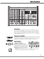 3
3
-
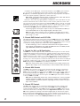 4
4
-
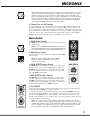 5
5
-
 6
6
-
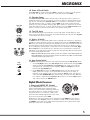 7
7
-
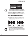 8
8
-
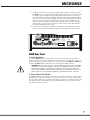 9
9
-
 10
10
-
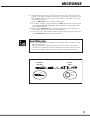 11
11
-
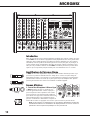 12
12
-
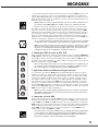 13
13
-
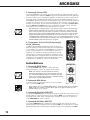 14
14
-
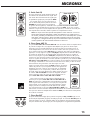 15
15
-
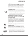 16
16
-
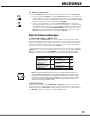 17
17
-
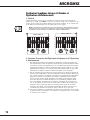 18
18
-
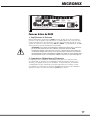 19
19
-
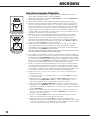 20
20
-
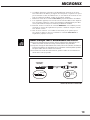 21
21
-
 22
22
-
 23
23
-
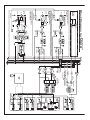 24
24
-
 25
25
-
 26
26


Yorkville Sound M608 YS 1088 Manuel utilisateur
- Catégorie
- Égaliseurs audio
- Taper
- Manuel utilisateur
dans d''autres langues
Documents connexes
-
Yorkville Sound YS 1088 Manuel utilisateur
-
-
Yorkville Sound M1610 Manuel utilisateur
-
-
-
-
Yorkville Sound YS1011 Manuel utilisateur
-
-
-
Autres documents
-
 YORKVILLE MP10DS Le manuel du propriétaire
-
 YORKVILLE M8 Le manuel du propriétaire
-
TRAYNOR YS1081 Le manuel du propriétaire
-
 YORKVILLE MM4D Le manuel du propriétaire
-
-
Samson XM410 spécification
-
 YORKVILLE MP8D Le manuel du propriétaire
-
 YORKVILLE PowerMAX2012 Le manuel du propriétaire
-
 YORKVILLE M1610-2 Le manuel du propriétaire
-
 YORKVILLE PGM8 Le manuel du propriétaire


