Delta 31-140 Le manuel du propriétaire
- Catégorie
- Ponceuses électriques
- Taper
- Le manuel du propriétaire

31140
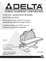
Lijadora de disco de 30,50 cm con
recolector de polvo integrado
Ponceuse à disque de 30,5cm avec
dispositif de dépoussiérage intégré
Operating Instructions and Parts Manual
Manuel d’utilisation
Manual de instrucciones
Français (14)
Español (27)
INSTRUCTIVO DE OPERACIÓN, CENTROS
DE SERVICIO Y PÓLIZA DE GARANTÍA.
LÉASE ESTE INSTRUCTIVO
ANTES DE USAR EL PRODUCTO.
www.DeltaMachinery.com
12 IN. DISC SANDER WITH INTEGRAL
DUST COLLECTION

2
TABLE OF CONTENTS
IMPORTANT SAFETY INSTRUCTIONS ...................................2
SAFETY GUIDELINES - DEFINITIONS ....................................3
GENERAL SAFETY RULES ......................................................3
POWER CONNECTIONS ..........................................................5
MOTOR SPECIFICATIONS .......................................................5
GROUNDING INSTRUCTIONS ................................................5
EXTENSION CORDS ................................................................6
FEATURES AND COMPONENTS .............................................6
FUNCTIONAL DESCRIPTION ...............................
.....
..............7
PRODUCT SPECIFICATIONS ...................................................7
UNPACKING ..............................................................................7
ASSEMBLY ................................................................................8
Install Brake Lever Assembly .....................................................................8
Secure Tool to Supporting Surface ........................................................8
Connect to Dust Hose to Dust Collector System ...............................8
OPERATION ..............................................................................9
Starting and Stopping ..................................................................................9
Removing the Safety Key to Lock the Sander .....................................9
Using the Manual Disc Brake .....................................................................
9
Angle
d and End Sanding Using The Miter Gauge ......................... 10
Bevel Sanding Using the Table Tilt .......................................................10
ADJUSTMENTS .......................................................................11
Adjust Miter Gauge Slot Alignment ...................................................11
Squaring the Table to the Sanding Disc .............................................11
RECOMMENDED MAINTENANCE ........................................12
Lubrication .....................................................................................................12
Routine Inspection ....................................................................................12
Replacing Sanding Disc ...........................................................................12
ACCESSORIES ........................................................................12
WARRANTY .............................................................................13
REPLACEMENT PARTS ..........................................................13
SE
RVICE
AND REPAIRS .........................................................13
FRANÇAIS ................................................................................14
ESPAÑOL .................................................................................27
IMPORTANT SAFETY INSTRUCTIONS
READ AND UNDERSTAND ALL WARNINGS AND OPERATING INSTRUCTIONS BEFORE USING THIS
EQUIPMENT. Failure to follow all instructions listed below, may result in electric shock, re, and/or
serious personal injury or property damage.
Woodworking can be dangerous if safe and proper operating procedures are not followed. As with all
machinery, there are certain hazards involved with the operation of the product. Using the machine with
respect and caution will considerably lessen the possibility of personal injury. However, if normal safety
precautions are overlooked or ignored, personal injury to the operator may result. Safety equipment such as
guards, push sticks, hold-downs, featherboards, goggles, dust masks and hearing protection can reduce your potential
for injury. But even the best guard won’t make up for poor judgment, carelessness or inattention. Always use common
sense and exercise caution in the workshop. If a procedure feels dangerous, don’t try it. Figure out an alternative
procedure that feels safer. REMEMBER: Your personal safety is your responsibility. For additional information please
visit our website www.DeltaMachinery.com.
This machine was designed for certain applications only. DELTA
®
Power Equipment Corporation strongly
recommends that this machine not be modied and/or used for any application other than that for
which it was designed. If you have any questions relative to a particular application, DO NOT use the machine until you
have rst contacted DELTA
®
to determine if it can or should be performed on the product.
If you have any questions relative to its application DO NOT use the product until you have written DELTA
®
Power Equipment
Corporation and we have advised you. Contact us online at www.DeltaMachinery.com or by mail at Technical Service Manager,
DELTA
®
Power Equipment Corporation, 2651 New Cut Road, Spartanburg, SC 29303.
Information regarding the safe and proper operation of this tool is available from the following sources:
• Power Tool Institute, 1300 Sumner Avenue, Cleveland, OH 44115-2851or online at www.powertoolinstitute.com
• National Safety Council, 1121 Spring Lake Drive, Itasca, IL 60143-3201
• American National Standards Institute, 25 West 43rd Street, 4 oor, New York, NY 10036 www.ansi.org - ANSI 01.1
Safety Requirements for Woodworking Machines
• U.S. Department of Labor regulations www.osha
.gov

3
SAFETY GUIDELINES - DEFINITIONS
This manual contains information that is important for you to know and understand. This information relates to protecting
YOUR SAFETY and PREVENTING EQUIPMENT PROBLEMS. To help you recognize this information, we use the
symbols below. Please read the manual and pay attention to these sections.
Indicates an imminently hazardous situation which, if not avoided, will result in death or serious injury.
Indicates a potentially hazardous situation which, if not avoided, could result in death or serious injury.
Indicates a potentially hazardous situation which, if not avoided, may result in minor or moderate injury.
Used without the safety alert symbol indicates potentially hazardous situation which, if not avoided, may
result in property damage.
GENERAL SAFETY RULES
WARNING FAILURE TO FOLLOW THESE RULES MAY RESULT IN SERIOUS PERSONAL INJURY.
•
FOR YOUR OWN SAFETY, READ AND UNDERSTAND THE INSTRUCTION MANUAL BEFORE OPERATING THE
UNIT.
Learn the unit’s application and limitations as well as the specific hazards peculiar to it.
•
KEEP WORK AREA CLEAN.
Cluttered areas and benches invite accidents.
•
DON’T USE IN DANGEROUS ENVIRONMENT.
Don’t use this unit in damp or wet locations, or expose it to rain. Keep
work area well-lighted.
•
KEEP CHILDREN AND VISITORS AWAY.
All children and visitors should be kept a safe distance from work area.
•
DISCONNECT UNIT
before servicing.
•
CHECK DAMAGED PARTS.
Before further use of the unit, properly repair or replace any part that is damaged.
1. Read and understand the warnings posted on the
machine and in this manual. Failure to comply with all
of these warnings may cause serious injury.
2. Replace the warning labels if they become obscured
or removed.
3. This Disc Sander is designed and intended for use
by properly trained and experienced personnel
only. If you are not familiar with the proper and safe
operation of an edge sander, do not use until proper
training and knowledge have been obtained.
4. Do not use this machine for other than its intended
use. If used for other purposes, DELTA
®
Power
Equipment Company, Inc. disclaims any real or
implied warranty and holds itself harmless from any
injury that may result from that use.
5. Always wear approved safety glasses/face shields
while using this disc sander.
6. Before operating this sander, remove tie, rings,
watches and other jewelry, and roll sleeves up past
the elbows. Remove all loose clothing and confine
long hair. Non-slip footwear or anti-skid floor strips
are recommended. Do not wear gloves.
7. Wear ear protectors (plugs or muffs) during extended
periods of operation.
8. Some dust created by power sanding, sawing,
grinding, drilling and other construction activities
contain chemicals known to cause cancer, birth
FAILURE TO FOLLOW THESE RULES MAY RESULT IN SERIOUS INJURY.
defects or other reproductive harm. Some examples
of these chemicals are:
• Lead from lead based paint.
• Crystalline silica from bricks, cement and other
masonry products.
• Arsenic and chromium from chemically treated lumber.
Your risk of exposure varies, depending on how often
you do this type of work. To reduce your exposure
to these chemicals, work in a well-ventilated area and
work with approved safety equipment, such as face or
dust masks that are specifically designed to filter out
microscopic particles.
9. Do not operate this machine while tired or under the
influence of drugs, alcohol or any medication.
10. Make certain the switch is in the OFF position before
connecting the machine to the power source.
11. Make certain the machine is properly grounded.
12. Make all machine adjustments or maintenance with
the machine unplugged from the power source.
13. Form a habit of checking to see that all extra
equipment such as adjusting keys, wrenches, scrap,
stock, and cleaning rags are removed away from the
machine before turning on.
14. Keep safety guards in place at all times when the
continued on page 4

4
machine is in use. If removed for maintenance
purposes, use extreme caution and replace the
guards immediately when maintenance is complete.
15. Make sure the sander is firmly secured before use.
16. Check damaged parts. Before further use of the
machine, a guard or other part that is damaged
should be carefully checked to determine that it will
operate properly and perform its intended function.
Check for alignment of moving parts, binding of
moving parts, breakage of parts, mounting and any
other conditions that may affect its operation. A guard
or other part that is damaged should be properly
repaired or replaced.
17. Provide for adequate space surrounding work area
and non-glare, overhead lighting.
18. Keep the floor around the machine clean and free of
scrap material, oil and grease.
19. Keep visitors a safe distance from the work area.
Keep children away.
20. Make your workshop child proof with padlocks,
master switches or by removing starter keys.
21. Give your work undivided attention. Looking around,
carrying on a conversation and “horse-play” are
careless acts that can result in serious injury.
22. Maintain a balanced stance at all times so that you
do not fall or lean against the sanding disc or other
moving parts. Do not overreach or use excessive
force to perform any machine operation.
23. Use the right tool at the correct speed and feed rate.
Do not force a tool or attachment to do a job for
which it was not designed. The right tool will do the
job better and safer.
24. Use recommended accessories; improper
accessories may be hazardous.
25. Maintain machinery with care. Follow instructions for
lubricating and changing accessories.
26. Turn off the machine before cleaning. Use a brush or
compressed air to remove dust or debris — do not
use your hands.
27. Do not stand on the machine. Serious injury could
occur if the machine tips over.
28. Never leave the machine running unattended. Turn
the power off and do not leave the machine until it
comes to a complete stop.
29. At all times hold the stock firmly.
30. Do not use this sander for other than it intended use.
If used for other purposes, DELTA® Power Equipment
Corporation. disclaims any real or implied warranty
and holds itself harmless for any injury or damage
which may result from that use.
Familiarize yourself with the following safety notices used
in this manual:
This means that if precautions are not heeded, it may
result in minor injury and/or possible machine damage.
This means that if precautions are not heeded, it may
result in serious injury or possibly even death.
SAVE THESE INSTRUCTIONS.
Refer to them often and use them to instruct others.

5
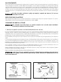
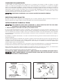
FIG. A FIG. B
GROUNDED
OUTLET BOX
CURRENT
CARRYING
PRONGS
GROUNDING BLADE
IS LONGEST OF THE 3 BLADES
GROUNDED OUTLET BOX
GROUNDING
MEANS
ADAPTER
POWER CONNECTIONS
A separate electrical circuit should be used for your machines. This circuit should not be less than #12 wire and should
be protected with a 20 Amp time lag fuse. If an extension cord is used, use only 3-wire extension cords which have
3-prong grounding type plugs and matching receptacle which will accept the machine’s plug. Before connecting the
machine to the power line, make sure the switch (s) is in the "OFF" position and be sure that the electric current is of
the same characteristics as indicated on the machine. All line connections should make good contact. Running on low
voltage will damage the machine.
DO NOT EXPOSE THE MACHINE TO RAIN OR OPERATE THE MACHINE IN DAMP LOCATIONS.
MOTOR SPECIFICATIONS
Your machine is wired for 115 volts, 60 HZ alternating current. Before connecting the machine to the power source,
make sure the switch is in the “OFF" position.
GROUNDING INSTRUCTIONS
THIS MACHINE MUST BE GROUNDED WHILE IN USE TO PROTECT THE OPERATOR FROM
ELECTRIC SHOCK.
1. All grounded, cord-connected machines:
In the event of a malfunction or breakdown, grounding provides a path of least resistance for electric current to reduce
the risk of electric shock. This machine is equipped with an electric cord having an equipment-grounding conductor and
a grounding plug. The plug must be plugged into a matching outlet that is properly installed and grounded in accordance
with all local codes and ordinances.
Do not modify the plug provided - if it will not fit the outlet, have the proper outlet installed by a qualified electrician.
Improper connection of the equipment-grounding conductor can result in risk of electric shock. The conductor with
insulation having an outer surface that is green with or without yellow stripes is the equipment-grounding conductor. If
repair or replacement of the electric cord or plug is necessary, do not connect the equipment-grounding conductor to a
live terminal.
Check with a qualified electrician or service personnel if the grounding instructions are not completely understood, or if
in doubt as to whether the machine is properly grounded.
Use only 3-wire extension cords that have 3-prong grounding type plugs and matching 3-conductor receptacles that
accept the machine’s plug, as shown in Fig. A.
Repair or replace damaged or worn cord immediately.
IN ALL CASES, MAKE CERTAIN THE RECEPTACLE IN QUESTION IS PROPERLY GROUNDED.
IF YOU ARE NOT SURE, HAVE A QUALIFIED ELECTRICIAN CHECK THE RECEPTACLE.

6
KEY FEATURES AND COMPONENTS
EXTENSION CORDS
Use proper extension cords. Make
sure your extension cord is in good
condition and is a 3-wire extension cord which has a
3-prong grounding type plug and matching
receptacle which will accept the machine’s plug.
When using an extension cord, be sure to use one
heavy enough to carry the current of the machine.
An undersized cord will cause a drop in line voltage,
resulting in loss of power and overheating. The table
shows the correct gauge to use depending on the
cord length. If in doubt, use the next heavier gauge.
The smaller the gauge number, the heavier the cord.
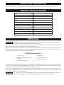
MINIMUM GAUGE EXTENSION CORD
RECOMMENDED SIZES FOR USE WITH STATIONARY ELECTRIC MACHINES
Ampere
Rating
Volts Total Length
of Cord in
Feet
Gauge of Extension
Cord
0-6
0-6
0-6
0-6
120
120
120
120
up to 25
25-50
50-100
100-150
18 AWG
16 AWG
16 AWG
14 AWG
6-10
6-10
6-10
6-10
120
120
120
120
up to 25
25-50
50-100
100-150
18 AWG
16 AWG
14 AWG
12 AWG
10-12
10-12
10-12
10-12
120
120
120
120
up to 25
25-50
50-100
100-150
16 AWG
16 AWG
14 AWG
12 AWG
12-16
12-16
12-16
120
120
120
up to 25
25-50
14 AWG
12 AWG
GREATER THAN 50 FEET NOT RECOMMENDED
FIG. C
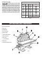
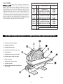
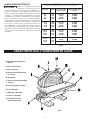
FIG. 1
A. Cast iron tilting table
B. Disc plate
C. Sanding disc
D. 2 1/4” dust port
E. Power switch
F. Table locking wing nut
G. Miter gauge slot
H. Disc brake
I. ½ HP, 120V motor
J. Safety key
K. Table tilt adjustment knob

7
The machine is heavy, be careful when removing it from the shipping container! Failure to comply may
cause serious injury and/or damage to the sander and/or property!
Your DELTA
®
12” Disc Sander comes packed in a single container. Use a safety strap to avoid tip-over when lifting
machine. Check shipping carton and machine for damage before unpacking.
Open the shipping container. Carefully remove packaging materials, parts and machine from shipping carton. Always
check for and remove protective shipping materials around motors and moving parts. Lay out all parts on a clean work
surface and check that all parts are present and in good condition:
PRODUCT SPECIFICATIONS
FUNCTIONAL DESCRIPTION
The DELTA
®
12” Disc Sander is designed for sanding or polishing flat or beveled surfaces on wood and plastic materials.
UNPACKING
DESCRIPTION (QUANTITY)
• 12” disc sander (1)
• Dust collection hose with 2 ¼” port
adaptor (1)
• Brake lever assembly (1)
• Miter gauge
• 2.5mm Allen wrench (1)
• 4mm Allen wrench (1)
Compare the items to inventory figures; verify that all items are accounted for before discarding the shipping box. Report
any missing or damaged parts to your distributor or dealer. Prior to tool assembly and use, read this manual thoroughly
to familiarize yourself with proper assembly, maintenance and safety procedures.
Remove any protective materials and coatings from all of the parts and the disc sander. The protective coatings can be
removed by spraying WD-40 on them and wiping it off with a soft cloth. This may need redone several times before all of
the protective coatings are removed completely
If any parts are missing, do not attempt to plug in the power cord and turn “ON" the machine. The
machine should only be turned “ON" after all the parts have been obtained and installed correctly.
Speed: 1725 RPM
Disc Diameter: 12”
Table Tilt: +45° to -45°
Height: 15”
Width: 17 ¼”
Shipping Weight: 81 lbs
Motor: ½ HP, 120 V, 1 Phase, 60 HZ
Table Size: 17 ¼” x 6 ¼”
Dust Collection Outlet: 2 ¼”
Miter Gauge Groove: 3/8” x 3/4"
Length: 17 ¾”
Weight: 72 lbs

8
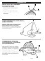
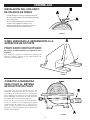
FIGURE 2
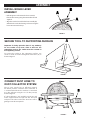
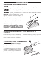
ASSEMBLY
INSTALL BRAKE LEVER
ASSEMBLY
• Refer to Figure 2 and remove the 2 hex screws (A)
from the disc housing using the 2.5mm Allen wrench
supplied.
• Align the screw holes in the brake lever assembly (B)
with the holes in the disc housing and secure using the
hex screws removed in Step 1.
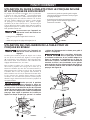
FIGURE 3
Important: If during operation there is any tendency
for the sander to tip over, slide or walk on the
supporting surface, the sander must be secured to
the supporting surface.
To secure the sander to the supporting surface, use
screws or bolts and nuts through the four holes (A) as
shown in Figure 3.
FIGURE 4
SECURE TOOL TO SUPPORTING SURFACE
A
The 12" Disc Sander has an efficient, integral
fan which provides excellent dust collection. It
is recommended that the machine be attached
to a dust collector using the 2 1/4” dust port (A)
shown in Figure 4.
If a dust collector is not available, insert one end
of the supplied dust hose (B) into the dust port
and place the other end of the dust hose into a
garbage can or other receptacle.
CONNECT DUST HOSE TO
DUST COLLECTOR SYSTEM

9
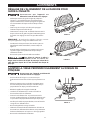
OPERATION
STARTING AND STOPPING SANDER
Failure to read and understand the instructions, warnings and safety guidelines provided in this manual
may lead to serious injury and / or damage to machine or the work piece.
Be sure the sanding disc is securely installed onto the disc plate.
Make sure the table tilt locking levers are secured and that the table is locked in place at the desired
angle or tilt.
Make sure the machine is installed on a flat, sturdy and stable surface able to support the weight of the
machine and the work piece to be sanded.
NOTE: The DELTA
®
12” Disc Sander uses a Safety Key
(A), shown in Figure 5. The Safety Key must be in place in
order to operate the machine. Before attempting to turn
on the sander, ensure the Safety Key is installed.
• The ON/OFF switch (B) is located on the top of the
motor. To turn the sander “ON”, move the switch
toward rear of sander.
• To turn the sander “OFF”, move switch to the front
position as shown.
NOTE: The sanding disc on this sander rotates
counterclockwise. In order to prevent injury and
produce good results, always sand on the left side
of the table only. Never work on the right side of the
table where the disc is rotating up as it is difficult to
control the work piece.
FIGURE 5
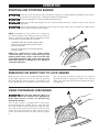
REMOVING THE SAFETY KEY TO LOCK SANDER
When the tool is not in use, the switch should be locked
in the “OFF” position. This can be done by grasping
the Safety Key (A), shown in Figure 5, and pulling it out
of the switch. With the Safety Key removed the switch
will not operate. Should the Safety Key be removed
while the machine is running, the switch can be turned
“OFF” once, but cannot be restarted without inserting
the Safety Key.
USING THE MANUAL DISC BRAKE
Apply the brake when the switch is in
the “off” position only. Applying the
brake while switch is in the “on” position may
damage the machine.
This 12" Disc Sander is equipped with a manual disc
brake that brings the sanding disc to a safe stop once
the power switch has been turned to the “OFF” position.
The manual disc brake should only be used once the
sander has been turned off. To apply the manual disc
brake, press down on brake lever (A) as shown in Figure
6.
FIGURE 6

10
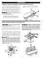
OPERATION
ANGLED AND END SANDING USING THE MITER GAUGE
The majority of work performed on the DELTA
®
12” Disc
Sander is usually accomplished using the table as a
support. For accurate sanding of angled and end-grain
surfaces, as shown in Figure 7, your disc sander comes
with an adjustable miter gauge (A) and 3/8" x 3/4" t-slot
(B) machined into the table. To use the provided miter
gauge for angled or end-grain sanding , do the following:
make certain machine is
disconnected from power source
before making adjustments.
• Slide the miter gauge into the t-slot.
• Loosen the miter adjustment handle (C) by rotating it
to the left and adjust the miter gauge to the desired
sanding angle. Tighten the miter adjustment handle.
FIGURE 7
BEVEL SANDING USING THE TABLE TILT
Make certain machine is
disconnected from power source
before making adjustments.
The table can be tilted up to 45 degrees up or down.
A scale (A), Figure 8, and pointer (B) are provided to
indicate the degree of tilt. Ball-indent positive stops on
the tilt adjustment indicator are located at 0°, 35°, and
45°.
To tilt the table up or down, loosen table locking wing
nut (C) and rotate the knob (D). As the knob is rotated,
the table will pivot either up or down. Turning the knob
clockwise will make the table tilt downward. Turning the
knob counterclockwise will tilt the table upward. Pivot
the table until desired angle is established. Then tighten
table locking wing nut.
Regardless of which position the
table is tilted, the table edge (E),
shown in Figure 10, must be no more than 1/16"
from the sanding disc to avoid trapping the work or
fingers between the table and sanding disc. To
adjust the position of the table relative to the
sanding disc, see “adjusting miter gauge slot
alignment “ on page 11.
FIGURE 8
FIGURE 9
We suggest that all bevel sanding
applications be performed with the
table tilted down as shown in Figure 9; however, if
there is a need to tilt the table up, the workpiece
must be securely fastened or clamped to a fixture or
jig to prevent the workpiece from being torn from
hands and becoming trapped between the table and
sanding disc. See Figure 10.
• Ensure the workpiece is positioned along the miter
gauge before turning the machine on and starting to
work.
FIGURE 10

11
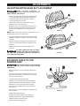
ADJUSTMENTS
ADJUSTING MITER GAGE SLOT ALIGNMENT
Make certain machine is
disconnected from power source
before making adjustments.
• Check to see if the miter gage slot (A), shown in Figure
11, is parallel with the disc by placing a combination
square in the miter gage slot with one end of the
square against the disc as shown.
• Using a pencil, make a mark on the abrasive disc
where the square contacts the disc.
• Rotate the disc 180° and check the distance between
the disc and miter gauge slot at the opposite end of
the table. If an adjustment is necessary, proceed as
follows:
NOTE: When making the following adjustment, ensure
the table locking wing nut is tightened.
• Using the supplied hex wrench, loosen the four screws
(B) indicated in Figure 12, which secure the table to the
trunnions.
• Adjust the table by moving it in or out until the miter
gage slot is equidistant from the disc at both ends of
the table.
• Tighten the four screws securing the table to the
trunnions.
To avoid trapping the work or fingers
between the table and sanding disc,
the table edge should be positioned a maximum of
1/16" from the sanding disc.
SQUARING TABLE TO THE
SANDING DISC
Make certain machine is disconnected
from power source before making
adjustments.
• Referring to Figure 13, ensure table tilt indicator (A) is
set to 0°.
• Place an accurate square on the table with one end of
the square against the disc. If the table is not square to
the disc, proceed as follows:
• Loosen the table locking wing nut (B).
• Locate the 0° set screw which is located beneath the
table and loosen the retaining nut on the set screw.
• Rotate the 0° set screw and re-measure using the
square, repeating until the table is square with the
abrasive disc.
• Once the table is square, retighten the retaining nut on
the 0° set screw.
• Tighten table locking wing nut.
• Re-calibrate table tilt indicator by loosening the
indicator retaining screw and positioning the tilt
indicator to the 0° mark on the scale.
• Tighten indicator retaining screw.
FIGURE 11
FIGURE 12
FIGURE 13

12
RECOMMENDED MAINTENANCE
NOTE: Disconnect machine from power source before
performing any maintenance.
LUBRICATION
All bearings are sealed and permanently lubricated. No
further lubrication is needed.
ROUTINE INSPECTION
It is recommended that you periodically inspect your
spindle sander as a precautionary action. During this
time, check for the following:
• Inspect all hardware, fittings and fasteners that may
have loosened due to vibration and re-tighten as
needed.
• Check for dust and/or wood particles that may have
accumulated on or in the machine. Check all dust
collection fittings – re-tighten as needed.
• Inspect the ON/OFF SWITCH for damage before each
use. Periodically inspect the power cord and plug for
damage. If necessary replace the power cord and the
plug at the first signs of visible damage.
REPLACING THE SANDING DISC
Make certain machine is
disconnected from power source.
• To remove sanding disc (A), simply peel old abrasive
disc from machine as shown.
• To install a new abrasive disc, make sure the disc plate
(B) is clean, dry, and free from any oil, grease, or old
adhesive.
• Peel back half the adhesive backing from the new disc
and slide between the table and disc plate so that the
half without the backing is aligned with the top half of
the disc plate.
• Press top half of sanding disc onto top half of disc
plate.
• Manually rotate disc plate one-half turn, remove
remainder of adhesive backing and firmly press sanding
disc onto disc plate.
Make certain the sanding disc is
securely in position before connecting
machine to a power source.
ACCESSORIES
A complete line of accessories is available from your DELTA
®
Supplier, DELTA
®
Factory Service Centers, and DELTA
®
Factory Service Centers, and DELTA
®
Authorized Service Centers. Please visit our Web Site www.DeltaMachinery.
com for an online catalog or for the name or your nearest supplier.
Since accessories other than those offered by DELTA
®
have not been tested with this product,
use of such accessories could be hazardous. For safest operation, only DELTA
®
recommended
accessories should be used with this product.
Five Year Limited New Product Warranty
DELTA
®
will repair or replace, at its expense and at its option, any new DELTA
®
machine, machine part, or machine accessory which in normal
use has proven to be defective in workmanship or material, provided that the customer returns the product prepaid to a DELTA
®
factory service
center or authorized service station with proof of purchase of the product within five years and provides DELTA
®
with reasonable opportunity
to verify the alleged defect by inspection. For all refurbished DELTA
®
product, the warranty period is 180 days. DELTA
®
will not be responsible
for any asserted defect which has resulted from normal wear, misuse, abuse or repair or alteration made or specifically authorized by anyone
other than an authorized DELTA
®
service facility or representative. Under no circumstances will DELTA
®
be liable for incidental or consequential
damages resulting from defective products. Some states do not allow the exclusion or limitation of incidental or consequential damages, so
the above limitation or exclusion may not apply to you. This warranty is DELTA
®
’s sole warranty and sets forth the customer’s exclusive remedy,
with respect to defective products; all other warranties, express or implied, whether of merchantability, fitness for purpose, or otherwise, are
expressly disclaimed by DELTA
®
. For further detail of warranty coverage and warranty repair information, visit www.DeltaMachinery.com or call
1-800-223-7278. This warranty gives you specific legal rights and you may have other rights which vary in certain states or provinces.
WARRANTY
To register your tool for warranty service visit our website at www.DeltaMachinery.com.
LATIN AMERICA: This warranty does not apply to products sold in Latin America. For products sold in Latin America, see country
specific warranty information contained in the packaging, call the local company or see website for warranty information.

13
PARTS, SERVICE OR WARRANTY ASSISTANCE
All DELTA
®
Machines and accessories are manufactured to high quality standards and are serviced by a network of
DELTA
®
Factory Service Centers and DELTA
®
Authorized Service Centers. To obtain additional information regarding
your DELTA
®
quality product or to obtain parts, service, warranty assistance, or the location of the nearest service center,
please call 1-800-223-7278.
REPLACEMENT PARTS
Use only identical replacement parts. For a parts list or to order parts, visit our website at www.DeltaMachinery.com. You can also order parts
from your nearest factory-owned branch, Authorized Warranty Service Center or by calling Technical Service Manager at 1-800-223-7278 to
receive personalized support from one of our highly-trained representatives.
FREE WARNING LABEL REPLACEMENT
If your warning labels become illegible or are missing, call
1-800-223-7278
for a free replacement.
SERVICE AND REPAIRS
All qualit y tools will eventually require servicing and/or replace ment of par ts. For infor mation
about D E LTA
®
Po w e r E qui pme n t C o r p o r a tion, its f a c t o r y - o w n e d b r a n ches , o r t o l o c a t e
an Auth o r i z ed Wa r r a nt y S e r vic e C e n t e r, visit our w ebsite a t www.De l taM achi nery. c o m
or call our Customer Care Center at 1-800-223-7278. All repairs made by our service centers are fully guaranteed against
defective material and workmanship. We cannot guarantee repairs made or attempted by others. By calling this number you
can also nd answers to most frequently asked questions.
You can also write to us
for information at DELTA
®
Power Equipment Corporation, 2651 New Cut Road,
Spartanburg, SC 29303 - Attention: Technical Service Manager. Be sure to include all of the information shown on
the nameplate of your tool (model number, type, serial number, date code, etc.)

14
CONSIGNES DE SÉCURITÉ IMPORTANTES
CONSIGNES DE SÉCURITÉ - DÉFINITIONS
ASSUREZ-VOUS D’AVOIR BIEN LU ET COMPRIS TOUTES LES MISES EN
GARDE ET LES CONSIGNES D’UTILISATION AVANT D’UTILISER CET
ÉQUIPEMENT. Le fait de ne pas respecter toutes les instructions ci-dessous, peut
avoir pour conséquence : choc électrique, incendie et/ou blessures graves ou dégâts matériels.
Le travail du bois peut être dangereux si des procédures d’utilisation sécuritaires et adéquates ne sont pas respectées.
Comme c’est le cas pour toute pièce de machinerie, l’utilisation de ce produit comporte certains dangers. En utilisant
cet appareil selon les directives et avec prudence, vous réduirez de façon importante les risques de blessures
corporelles. Cependant, si les précautions normales de sécurité sont négligées ou ignorées, la personne qui utilise
l’appareil pourrait être blessée. L’équipement de protection comme les gardes, les poussoirs, les dispositifs de retenue,
les planches de protection, les lunettes de sécurité, les masques antipoussière et la protection pour l’ouïe peut réduire
le risque de blessure. Cependant, même le meilleur dispositif de protection ne peut compenser un mauvais jugement,
un manque de prudence ou de l’inattention. Ayez toujours recours à votre bon sens et soyez prudent dans l’atelier. Si
une manœuvre a l’air dangereuse, ne l’eectuez pas. Essayez plutôt de trouver un moyen plus facile. RAPPELEZ-VOUS
: Vous êtes responsable de votre propre sécurité. Pour des renseignements complémentaires, rendez-vous sur notre site
web à l’adresse www.DeltaMachinery.com.
Cet appareil a été conçu seulement pour certains types d’utilisation. DELTA
MD
Power
Equipment Corporation recommande fortement que cet appareil ne soit ni modié ni utilisé à
toute autre n que celles pour lesquelles il a été conçu. Si vous avez des questions sur un type d’utilisation en particulier,
N’UTILISEZ PAS l’appareil avant d’avoir d’abord contacté DELTA
MD
pour déterminer si elle peut ou si elle devrait être
réalisée avec ce produit.
Si vous avez des questions sur son utilisation, N’UTILISEZ PAS le produit tant que vous n’avez pas écrit à DELTA
MD
Power
Equipment Corporation et obtenu une réponse de leur part. Contactez-nous en ligne sur www.DeltaMachinery.com ou par
MD
Power Equipment Corporation, 2651 New Cut
Road, Spartanburg, SC 29303.
• Des renseignements au sujet de l’utilisation sécuritaire et appropriée de cet appareil sont disponibles auprès des sources
• Power Tool Institute, 1300 Sumner Avenue, Cleveland, OH 44115-2851 ou en ligne à l’adresse www.powertoolinstitute.
com
• National Safety Council, 1121 Spring Lake Drive, Itasca, IL 60143-3201
• American National Standards Institute, 25 West 43rd Street, 4 oor, New York, NY 10036 ou en ligne à l’adresse www.
ansi.org - ANSI 01.1 Safety Requirements for Woodworking Machines
• Réglementation du Département américain du travail (OSHA) à l’adresse www.osha.gov
Ce manuel contient des informations qu’il est important de connaître et de comprendre. Ces informations ont pour but
d’assurer VOTRE SÉCURITÉ et de PRÉVENIR LES PROBLÈMES D’ÉQUIPEMENT. Pour vous aider à reconnaître ces
informations, nous utilisons les symboles ci-dessous. Veuillez lire le manuel et prêter attention à ces sections-là.
Indique une situation extrêmement dangereuse qui, si elle n’est pas évitée, entraînera la mort ou une
blessure grave.
Indique une situation potentiellement dangereuse qui, si elle n’est pas évitée, pourrait entraîner
la mort ou une blessure grave.
Indique
une situation potentiellement dangereuse qui, si elle n’est pas évitée, peut entraîner une
blessure mineure ou modérée.
Utilisé sans le symbole d’avertissement, indique une situation potentiellement dangereuse qui, si elle
n’est pas évitée, peut endommager l’appareil.

15
LE NON-RESPECT DE CES RÈGLES PEUT ENTRAÎNER DES BLESSURES GRAVES.
RÈGLES DE SÉCURITÉ GÉNÉRALES
LE NON-RESPECT DE CES RÈGLES PEUT ENTRAÎNER DES BLESSURES
PERSONNELLES GRAVES.
•
POUR VOTRE PROPRE SÉCURITÉ, ASSUREZ-VOUS D’AVOIR BIEN LU ET COMPRIS LE MANUEL
D’UTILISATION AVANT DE FAIRE FONCTIONNER L’APPAREIL.
Apprenez à connaître son domaine d’utilisation et
ses limites, ainsi que les dangers qui lui sont rattachés.
•
MAINTENEZ L’AIRE DE TRAVAIL PROPRE.
Les aires et les bancs de travail encombrés sont propices aux accidents.
•
NE PAS UTILISER DANS UN ENVIRONNEMENT DANGEREUX.
N’utilisez pas cet appareil dans un endroit humide
ou mouillé, et ne l’exposez pas à la pluie. Gardez votre lieu de travail bien éclairé.
•
MAINTENEZ LES ENFANTS ET LES VISITEURS À L’ÉCART.
Tous les enfants et visiteurs doivent demeurer à une
distance sécuritaire de l’aire de travail.
•
DÉBRANCHEZ L’APPAREIL
avant toute opération d’entretien.
•
VÉRIFIEZ LA PRÉSENCE DE PARTIES ENDOMMAGÉES.
Avant d’utiliser l’appareil, assurez-vous de bien réparer ou
remplacer toute partie endommagée.
1. Assurez-vous de lire et comprendre les
avertissements affichés sur l’appareil et dans ce
manuel. Le non-respect de tous ces avertissements
peut entraîner des blessures graves.
2. Remplacer les étiquettes d’avertissement si elles sont
masquées ou si elles ont été retirées.
3. Cette ponceuse à disque est conçue pour l’utilisation
par un personnel qualifié et expérimenté seulement.
Si vous n’avez pas l’habitude d’utiliser correctement
et en toute sécurité une ponceuse de contour,
ne vous en servez pas avant d’avoir acquis les
connaissances et la formation appropriées.
4. Ne pas utiliser cet appareil pour autre chose que
son usage prévu. S’il est utilisé à d’autres fins,
DELTA
MD
Power Equipment Company, Inc. décline
toute garantie réelle ou implicite et se dégage de
toute responsabilité pour toute blessure qui pourrait
résulter de cette utilisation.
5. Portez toujours des lunettes/masque de protection
agréés durant l’utilisation de cette ponceuse à
disque.
6. Avant d’utiliser cette ponceuse, enlevez cravate,
bagues, montres et autres bijoux, et retroussez vos
manches au-dessus du coude. Retirez tous les
vêtements amples et retenez les cheveux longs.
Il est recommandé de porter des chaussures
antidérapantes ou de poser des bandes de plancher
antidérapantes. Ne pas porter de gants.
7. Portez des protecteurs pour l’ouïe (bouchons ou
manchons) pendant les longues périodes d’utilisation.
8. Certaines poussières produites par les activités
de ponçage, de sciage, de meulage, de perçage
ainsi que d’autres activités de construction peuvent
contenir des produits chimiques pouvant causer
le cancer, des anomalies congénitales ou d’autres
problèmes liés aux fonctions reproductrices. En voici
des exemples:
• Plomb de peintures à base de plomb;
• Silice cristalline de briques, de ciment et d’autres
produits de maçonnerie;
• Arsenic et chrome de bois de sciage traité
chimiquement.
Votre risque à ces expositions varie, selon la
fréquence à laquelle vous effectuez ce genre
d’activité. Pour réduire l’exposition à ces produits
chimiques, travaillez dans un endroit bien ventilé et avec
de l’équipement de protection approuvé, comme les
masques antipoussières spécialement conçus pour filtrer
les particules microscopiques
9. Ne pas utiliser cet appareil en état de fatigue ou avec
les facultés affaiblies par la drogue, l’alcool ou les
médicaments.
10 Avant de brancher l’appareil sur la source
d’alimentation, assurez-vous que le commutateur est
en position «OFF» (« Arrêt»).
11. Assurez-vous que la machine est correctement mise
à la terre.
12. Faites les réglages de la machine ou son entretien
que lorsque celle-ci est débranchée de la source
d’alimentation.
13. Prenez l’habitude de vérifier que tout l’équipement
supplémentaire comme les clés de réglage, les clés
à molette, la ferraille, le matériel et les chiffons de
nettoyage a été éloigné de la machine avant de la
mettre en marche.
14. Gardez les dispositifs de protection en place en tout
temps lorsque l’appareil est utilisé. Faites preuve
d’une extrême prudence s’ils sont enlevés à des
fins d’entretien et remettez-les en place dès la fin de
l’entretien.
15. Assurez-vous de la stabilité de la ponceuse avant de
l’utiliser.
16. Vérifiez si des parties sont endommagées. Avant
d’utiliser l’appareil, il faut vérifier soigneusement
le dispositif de protection ou toute autre partie
endommagée afin de s’assurer que l’appareil
fonctionnera correctement et remplira sa fonction
prévue. Vérifiez l’alignement des pièces mobiles

16
CONSERVER CES CONSIGNES.
Consultez-les souvent et utilisez-les pour enseigner aux autres.
et leurs joints, tout bris de pièce et du cadrage et
toute autre condition qui pourrait en modifier
le fonctionnement. Toute garde ou autre partie
endommagée doit être réparée ou remplacée sans
délai.
17. Prévoyez un espace suffisant autour de la zone de
travail et un éclairage en plongée non éblouissant.
18. Gardez le plancher autour de l’appareil propre et
exempt de débris, d’huile et de graisse.
19. Gardez les visiteurs à une distance sécuritaire de la
zone de travail. Tenez les enfants à distance.
20. Sécurisez votre atelier pour les enfants avec des
cadenas, des commutateurs principaux ou en retirant
les clés de mise en marche.
21. Concentrez-vous uniquement sur le travail. Regarder
aux alentours, tenir une conversation et faire du
« chahut » sont des actes négligents qui peuvent
entraîner des blessures graves.
22. Ayez toujours une posture stable afin de ne pas
tomber et de ne pas vous appuyer contre le disque
de ponçage ou d’autres éléments en mouvement.
Évitez de vous pencher trop en avant ou de forcer de
manière excessive en utilisant l’appareil.
23. Utilisez l’outil approprié à la bonne vitesse et au
bon débit. Ne forcez pas un outil ou un accessoire
à effectuer une tâche pour laquelle il n’a pas été
conçu. Le bon outil fera mieux le travail et sera plus
sécuritaire.
24. Utilisez les pièces recommandées. Les accessoires
inadéquats peuvent être dangereux.
25. Entretenez les appareils avec soin. Suivez les
indications pour la lubrification et le changement
d’accessoires.
26. Débranchez l’appareil avant le nettoyage. Utilisez une
brosse ou de l’air comprimé pour enlever la poussière
ou des débris; n’utilisez pas vos mains.
27. Ne vous tenez pas debout sur l’appareil. Des
blessures graves pourraient se produire si l’appareil
se renverse.
28. Ne jamais laisser l’appareil sans surveillance lorsqu’il
est en marche. Débranchez l’appareil et ne le laissez
pas sans surveillance jusqu’à son arrêt complet.
29. Tenez la poignée fermement en tout temps.
30. N’utilisez pas cette ponceuse pour d’autres fins
que celles pour lesquelles elle est prévue. Si elle est
utilisée à d’autres fins, DELTAMD Power Equipment
Company Inc. décline toute garantie réelle ou
implicite et se dégage de toute responsabilité pour
toute blessure qui pourrait résulter de cette utilisation.
Familiarisez-vous avec les règles de sécurité enseignées
dans ce manuel:
Cela signifie que le non-respect des précautions peut
entraîner des blessures superficielles et/ou endommager
l’appareil.
Cela signifie que le non-respect des précautions peut
causer des blessures graves pouvant même entraîner la
mort.

17
FIG. A FIG. B
BOÎTE DE COURANT
DE MISE À LA
TERRE
BROCHES
PORTEUSES DE
COURANT
LA BROCHE DE
MISE À LA TERRE EST LA PLUS
LONGUE DES TROIS
BOÎTE DE COURANT
DE MISE À LA TERRE
MOYENS DE MISE
À LA TERRE
ADAPTATEUR
RACCORDEMENTS
Un circuit électrique séparé devrait être utilisé pour vos appareils. Les fils du circuit doivent être au moins de calibre 12
et être protégés par un fusible à action différée de 20ampères. Si vous utilisez une rallonge, ne prenez que des rallonges
à troisfils avec des fiches de mise à la terre à troisbroches et le réceptacle correspondant qui acceptera la fiche de
l’appareil. Avant de brancher l’appareil sur l’alimentation, assurez-vous que le commutateur est en position «OFF »
(«Arrêt ») et que le courant électrique que vous allez utiliser possède les mêmes caractéristiques que celui indiqué
sur l’appareil. Tous les raccordements doivent établir un bon contact. Une utilisation en basse tension endommagera
l’appareil.
NE PAS UTILISER L’APPAREIL DANS UN ENDROIT HUMIDE OU MOUILLÉ ET NE PAS
L’EXPOSER À LA PLUIE.
SPÉCIFICATIONS DU MOTEUR
Votre appareil est câblé pour un courant alternatif de 115Volts, 60 Hz. Avant de raccorder l’appareil à la source
d’alimentation, assurez-vous que l’interrupteur est positionné sur «OFF» (ARRÊT).
CONSIGNES DE MISE À LA TERRE
CET APPAREIL DOIT ÊTRE MIS À LA TERRE LORSQU’IL EST UTILISÉ POUR PROTÉGER
L’OPÉRATEUR CONTRE L’ÉLECTROCUTION.
1. Pour tous les appareils raccordés à un cordon d’alimentation et mis à la terre :
En cas demauvais fonctionnement ou de panne, lamise à la terre fournit un chemin demoindre résistance au courant
électrique visant à réduire le risque d’électrocution. Cet appareil est équipé d’un cordon électrique possédant un
conducteur de terre et une fiche de terre. La fiche doit être branchée sur une prise correspondante qui est correctement
installée etmise à la terre, conformément à tous les codes et les règlements locaux.
Ne pasmodifier la fiche prévue. Si elle n’entre pas dans la prise, faire installer une prise appropriée par un électricien
agréé.
Le raccordement inapproprié du conducteur de terre de l’équipement peut provoquer l’électrocution. Le fil conducteur
avec un isolant comportant une surface extérieure verte, avec ou sans rayures jaunes, est le conducteur de terre. Si la
réparation ou le remplacement du cordon électrique ou de la fiche s’avère nécessaire, ne pas raccorder le conducteur de
terre de l’équipement à une borne sous tension.
Si les consignes demise à la terre ne sont pas complètement comprises ou en cas de doute concernant la mise à la
terre de l’appareil, se renseigner auprès d’un électricien ou du personnel de service agréés.
Utiliser uniquement des rallonges à troisfils avec des fiches demise à la terre à troisbroches et des réceptacles adaptés
à la fiche de l’appareil, comme indiqué à la Fig.A.
Réparer ou remplacer immédiatement tout cordon endommagé ou usé.
DANS TOUS LES CAS, ASSUREZ-VOUS QUE LE RÉCEPTACLE EN QUESTION EST BIEN RELIÉ
À LA TERRE. SI VOUS N’ÊTES PAS CERTAIN, FAITES VÉRIFIER LE RÉCEPTACLE PAR UN
ÉLECTRICIEN QUALIFIÉ.

18
CARACTÉRISTIQUES ET COMPOSANTES IMPORTANTES
RALLONGES
Utiliser des rallonges appropriées.
S’assurer que la rallonge est en bon
état et qu’il s’agit d’une rallonge à trois fils avec une
fiche de mise à la terre à troisbroches et d’un réceptacle
correspondant à la fiche de l’appareil. Lorsque vous
utilisez une rallonge, assurez-vous qu’elle soit de calibre
suffisamment élevé pour assurer l’alimentation de
l’appareil. Une rallonge d’un calibre trop petit provoquera
une chute de tension, entraînant une perte de puissance
et une surchauffe. Le tableau indique le bon calibre à
utiliser en fonction de la longueur de la rallonge. En cas de
doute, utiliser le calibre immédiatement supérieur. Plus le
numéro de calibre est petit, plus le cordon est épais.
FIG. C
A. Table en fonte inclinable
B. Support de disque
C. Disque de ponçage
D. Sortie de poussière de 5,71 cm
E. Interrupteur
F. Papillon de serrage de la table
G. Rainure pour guide à onglets
H. Frein à disque
I. Moteur de 1/2 HP, 120 V
J. Clé de sécurité
K. Bouton de réglage de l’inclinaison
de la table
CALIBRE MINIMUM POUR RALLONGE
CALIBRES RECOMMANDÉS POUR UTILISATION SUR DES APPAREILS ÉLECTRIQUES STATIONNAIRES
Ampérage Volts Longueur totale du
cordon en pieds
Calibre de la
rallonge
0 À 6
0 À 6
0 À 6
0 À 6
120
120
120
120
JUSQU’À 25 PI
25 À 50 (7,62 À 15,24 M)
50 À 100 (15,24 À 30,48 M)
100 À 150 (30,48 À 45,72 M)
18 AWG
16 AWG
16 AWG
14 AWG
6 À 10
6 À 10
6 À 10
6 À 10
120
120
120
120
JUSQU’À 25 PI
25 À 50 (7,62 À 15,24 M)
50 À 100 (15,24 À 30,48 M)
100 À 150 (30,48 À 45,72 M)
18 AWG
16 AWG
14 AWG
12 AWG
10 À 12
10 À 12
10 À 12
10 À 12
120
120
120
120
JUSQU’À 25 PI
25 À 50 (7,62 À 15,24 M)
50 À 100 (15,24 À 30,48 M)
100 À 150 (30,48 À 45,72 M)
16 AWG
16 AWG
14 AWG
12 AWG
12 À 16
12 À 16
12 À 16
120
120
120
JUSQU’À 25 PI
25 À 50 (7,62 À 15,24 M)
14 AWG
12 AWG
UNE LONGUEUR DE PLUS DE 50PI N’EST PAS RECOMMANDÉE.
FIG. 1

19
SPÉCIFICATIONS DU PRODUIT
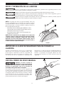
DESCRIPTION FONCTIONNELLE
DÉBALLAGE
L’appareil est lourd, soyez prudent lorsque vous le retirez de l’emballage d’expédition! Le non-
respect des indications peut entraîner des blessures graves et/ou endommager la ponceuse et/
ou le matériel!
Votre ponceuse à disque DELTA
MD
de 30,5cm est livrée dans un emballage unique. Placez une sangle de sécurité autour
de l’appareil pour éviter qu’il ne bascule lors du levage. Vérifiez la présence de dommages sur le carton d’expédition et
l’appareil avant de le déballer.
Ouvrez l’emballage d’expédition. Enlevez soigneusement les matériaux d’emballage, les pièces et l’appareil de
l’emballage d’expédition. Toujours vérifier et retirer les matériaux d’emballage de protection autour des moteurs et des
pièces mobiles. Étalez toutes les pièces sur une surface de travail propre et vérifiez que toutes les pièces sont présentes
et en bon état:
La ponceuse à disque DELTA
MD
de 30,5cm est conçue pour poncer ou polir les surfaces plates ou inclinées sur des
matériaux en bois et en plastique.
DESCRIPTION (QUANTITÉ)
• Ponceuse à disque de 30,5cm (1)
• Tuyau de dépoussiérage avec sortie de
poussière de 5,71cm adaptateur (1)
• Ensemble de levier de frein (1)
• Guide à onglets
• Clé Allen de 2,5mm (1)
• Clé Allen de 4mm (1)
Comparez les articles avec la liste d’inventaire. Vérifiez la présence de tous les éléments avant de jeter la boîte
d’expédition. Signalez toute pièce manquante ou endommagée à votre distributeur ou à votre revendeur. Avant de
passer à l’assemblage de l’appareil et à son utilisation, lisez attentivement le présent manuel pour vous familiariser avec
les procédures d’assemblage, d’entretien et de sécurité appropriées.
Retirez tout matériau de protection et tout emballage de l’ensemble des éléments et de la ponceuse à disque. Les
enduits de protection peuvent être enlevés en les pulvérisant de WD-40 et en les essuyant avec un chiffon doux. Il peut
être nécessaire de répéter cette étape plusieurs fois pour enlever l’intégralité des enduits de protection.
S’il y a des pièces manquantes, n’essayez pas de brancher le cordon d’alimentation et de
mettre l’appareil en marche (« ON »). L’appareil doit seulement être mis en marche (« ON »)
quand toutes les pièces auront été obtenues et correctement installées.
Vitesse : 1725 tr/min
Diamètre du disque : 30,5cm
Inclinaison de la table : de +45° à -45°
Hauteur : 38,10cm
Largeur : 43,81cm
Poids à l’expédition : 36,74kg
Moteur : 1/2 HP, 120V, 1Phase, 60Hz
Dimension de la table : 43,81cm par 15,87cm
Orifice de dépoussiérage: 5,71cm
Rainure pour guide à onglets : 0,95 cm par 1,90cm
Longueur : 45,08cm
Poids : 32,65kg

20
ASSEMBLAGE
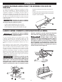
FIGURE 2
INSTALLATION DE L’ENSEMBLE
DE LEVIER DE FREIN
• Référez-vous à la Figure2 et retirez les 2vis à 6pans
(A) du support de disque en utilisant la clé Allen de
2,5mm fournie.
• Alignez les trous de vis de l’ensemble de levier de
frein (B) avec ceux du support de disque et fixez ces
deux parties en utilisant les vis à 6 pans que vous avez
retirées à l’étape1.
FIGURE 3
Important : Pendant l’utilisation, si la ponceuse a
tendance à basculer, glisser ou se déplacer, celle-ci
doit être solidement fixée sur la surface d’appui.
Pour fixer la ponceuse sur la surface d’appui, placez des
vis ou des boulons et des écrous dans les quatre trous
(A) comme indiqué à la Figure 3.
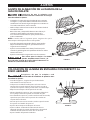
FIGURE 4
POSITIONNEMENT DE L’OUTIL SUR LA
SURFACE D’APPUI
A
La ponceuse à disque de 30,5cm a un ventilateur
intégré efficace qui permet une excellente
récupération de la poussière. Il est recommandé
de connecter l’appareil à un dispositif de
dépoussiérage avec la sortie de poussière de
5,71cm (A) comme indiqué à la Figure4.
Si vous ne possédez pas de dispositif de
dépoussiérage, insérez une extrémité du tuyau
fourni (B) dans la sortie de poussière et placez
l’autre extrémité du tuyau dans une poubelle ou
tout autre récipient.
CONNEXION DU TUYAU DE
DÉPOUSSIÉRAGE AU SYSTÈME
DE DEPOUSSIÉRAGE
La page est en cours de chargement...
La page est en cours de chargement...
La page est en cours de chargement...
La page est en cours de chargement...
La page est en cours de chargement...
La page est en cours de chargement...
La page est en cours de chargement...
La page est en cours de chargement...
La page est en cours de chargement...
La page est en cours de chargement...
La page est en cours de chargement...
La page est en cours de chargement...
La page est en cours de chargement...
La page est en cours de chargement...
La page est en cours de chargement...
La page est en cours de chargement...
La page est en cours de chargement...
La page est en cours de chargement...
La page est en cours de chargement...
La page est en cours de chargement...
-
 1
1
-
 2
2
-
 3
3
-
 4
4
-
 5
5
-
 6
6
-
 7
7
-
 8
8
-
 9
9
-
 10
10
-
 11
11
-
 12
12
-
 13
13
-
 14
14
-
 15
15
-
 16
16
-
 17
17
-
 18
18
-
 19
19
-
 20
20
-
 21
21
-
 22
22
-
 23
23
-
 24
24
-
 25
25
-
 26
26
-
 27
27
-
 28
28
-
 29
29
-
 30
30
-
 31
31
-
 32
32
-
 33
33
-
 34
34
-
 35
35
-
 36
36
-
 37
37
-
 38
38
-
 39
39
-
 40
40


Delta 31-140 Le manuel du propriétaire
- Catégorie
- Ponceuses électriques
- Taper
- Le manuel du propriétaire
dans d''autres langues
- English: Delta 31-140 Owner's manual
- español: Delta 31-140 El manual del propietario