
PART NO. 491836-00 REV. 1 05-18-06
Copyright © 2006 Delta Machinery
ESPAÑOL: PÁGINA 23
To learn more about DELTA MACHINERY
visit our website at: www.deltamachinery.com.
For Parts, Service, Warranty or other Assistance,
please call 1-800-223-7278 (In Canada call 1-800-463-3582).
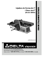
4" Belt / 6" Disc Sander
(Model SM500)
FRANÇAIS: PAGE 45

2
TABLE OF CONTENTS
Read and understand all warnings and operating instructions before using any tool or equipment. When
using tools or equipment, basic safety precautions should always be followed to reduce the risk of personal injury.
Improper operation, maintenance or modification of tools or equipment could result in serious injury and property
damage. There are certain applications for which tools and equipment are designed. Delta Machinery strongly
recommends that this product NOT be modified and/or used for any application other than for which it was designed.
If you have any questions relative to its application DO NOT use the product until you have written Delta Machinery
and we have advised you.
Online contact form at www.deltamachinery.com
Postal Mail: Technical Service Manager
Delta Machinery
4825 Highway 45 North
Jackson, TN 38305
(IN CANADA: 505 SOUTHGATE DRIVE, GUELPH, ONTARIO N1H 6M7)
Information regarding the safe and proper operation of this tool is available from the following sources:
Power Tool Institute
1300 Sumner Avenue, Cleveland, OH 44115-2851
www.powertoolinstitute.org
National Safety Council
1121 Spring Lake Drive, Itasca, IL 60143-3201
American National Standards Institute, 25 West 43rd Street, 4 floor, New York, NY 10036 www.ansi.org
ANSI 01.1Safety Requirements for Woodworking Machines, and
the U.S. Department of Labor regulations www.osha.gov
IMPORTANT SAFETY INSTRUCTIONS
SAVE THESE INSTRUCTIONS!
IMPORTANT SAFETY INSTRUCTIONS . . . . . . . . . . . . . . . . . . . . . . . . . . . . . . . . . . . . . . . . . . . . . . . . . . . . . . . . . . .2
SAFETY GUIDELINES . . . . . . . . . . . . . . . . . . . . . . . . . . . . . . . . . . . . . . . . . . . . . . . . . . . . . . . . . . . . . . . . . . . . . . . .3
GENERAL SAFETY RULES . . . . . . . . . . . . . . . . . . . . . . . . . . . . . . . . . . . . . . . . . . . . . . . . . . . . . . . . . . . . . . . . . . . .4
ADDITIONAL SPECIFIC SAFETY RULES . . . . . . . . . . . . . . . . . . . . . . . . . . . . . . . . . . . . . . . . . . . . . . . . . . . . . . . . .5
FUNCTIONAL DESCRIPTION . . . . . . . . . . . . . . . . . . . . . . . . . . . . . . . . . . . . . . . . . . . . . . . . . . . . . . . . . . . . . . . . . .7
CARTON CONTENTS . . . . . . . . . . . . . . . . . . . . . . . . . . . . . . . . . . . . . . . . . . . . . . . . . . . . . . . . . . . . . . . . . . . . . . . . .8
ASSEMBLY . . . . . . . . . . . . . . . . . . . . . . . . . . . . . . . . . . . . . . . . . . . . . . . . . . . . . . . . . . . . . . . . . . . . . . . . . . . . . . . . .9
OPERATION . . . . . . . . . . . . . . . . . . . . . . . . . . . . . . . . . . . . . . . . . . . . . . . . . . . . . . . . . . . . . . . . . . . . . . . . . . . . . . .13
TROUBLESHOOTING . . . . . . . . . . . . . . . . . . . . . . . . . . . . . . . . . . . . . . . . . . . . . . . . . . . . . . . . . . . . . . . . . . . . . . .20
MAINTENANCE . . . . . . . . . . . . . . . . . . . . . . . . . . . . . . . . . . . . . . . . . . . . . . . . . . . . . . . . . . . . . . . . . . . . . . . . . . . . .21
SERVICE . . . . . . . . . . . . . . . . . . . . . . . . . . . . . . . . . . . . . . . . . . . . . . . . . . . . . . . . . . . . . . . . . . . . . . . . . . . . . . . . . .21
ACCESSORIES . . . . . . . . . . . . . . . . . . . . . . . . . . . . . . . . . . . . . . . . . . . . . . . . . . . . . . . . . . . . . . . . . . . . . . . . . . . .21
WARRANTY . . . . . . . . . . . . . . . . . . . . . . . . . . . . . . . . . . . . . . . . . . . . . . . . . . . . . . . . . . . . . . . . . . . . . . . . . . . . . . . .22
ESPAÑOL . . . . . . . . . . . . . . . . . . . . . . . . . . . . . . . . . . . . . . . . . . . . . . . . . . . . . . . . . . . . . . . . . . . . . . . . . . . . . . . . .23
FRENCH . . . . . . . . . . . . . . . . . . . . . . . . . . . . . . . . . . . . . . . . . . . . . . . . . . . . . . . . . . . . . . . . . . . . . . . . . . . . . . . . . .45
SERVICE CENTER LOCATIONS . . . . . . . . . . . . . . . . . . . . . . . . . . . . . . . . . . . . . . . . . . . . . . . . . . . . . . . .back cover

3
Indicates an imminently hazardous situation which, if not avoided, will result in death or serious injury.
Indicates a potentially hazardous situation which, if not avoided, could result in death or serious injury.
Indicates a potentially hazardous situation which, if not avoided, may result in minor or moderate injury.
Used without the safety alert symbol indicates potentially hazardous situation which, if not avoided, may result
in property damage.
It is important for you to read and understand this manual. The information it contains relates to protecting
YOUR SAFETY and PREVENTING PROBLEMS. The symbols below are used to help you recognize this
information.
SAFETY GUIDELINES - DEFINITIONS
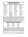
Some dust created by power sanding, sawing, grinding, drilling, and other construction activities contains
chemicals known to cause cancer, birth defects or other reproductive harm. Some examples of these
chemicals are:
• lead from lead-based paints,
• crystalline silica from bricks and cement and other masonry products, and
• arsenic and chromium from chemically-treated lumber (CCA).
Your risk from these exposures varies, depending on how often you do this type of work. To reduce your exposure to these
chemicals: work in a well ventilated area, and work with approved safety equipment, such as those dust masks that are specially
designed to filter out microscopic particles.
• Avoid prolonged contact with dust from power sanding, sawing, grinding, drilling, and other construction activities. We a r
protective clothing and wash exposed areas with soap and water. Allowing dust to get into your mouth, eyes, or lay on the skin
may promote absorption of harmful chemicals.
Use of this tool can generate and/or disperse dust, which may cause serious and permanent respiratory or other injury.
Always use NIOSH/OSHA approved respiratory protection appropriate for the dust exposure. Direct particles away from face and
b o d y.
Wear appropriate hearing protection during use. Under some conditions and duration of use, noise from this product may
contribute to hearing loss.
CALIFORNIA PROPOSITION 65
SANDING LEAD BASED PA I N T
Sanding of lead based paint is NOT RECOMMENDED due to the difficulty of controlling the contaminated dust. The greatest
danger of lead poisoning is to children and pregnant women.
Since it is difficult to identify whether or not a paint contains lead without a chemical analysis, we recommend the following
precautions when sanding any paint:
P E R S O N A L S A F E T Y
• No children or pregnant women should enter the work area where the paint sanding is being done until all clean up is
c o m p l e t e d .
• A dust mask or respirator should be worn by all persons entering the work area. The filter should be replaced daily or
whenever the wearer has difficulty breathing.
NOTE: Only those dust masks suitable for working with lead paint dust and fumes should be used. Ordinary painting masks
do not offer this protection. See your local hardware dealer for the proper (NIOSH approved) mask.
• NO EATING, DRINKING or SMOKING should be done in the work area to prevent ingesting contaminated paint particles.
Workers should wash and clean up BEFORE eating, drinking or smoking. Articles of food, drink, or smoking should not be
left in the work area where dust would settle on them.
E N V I R O N M E N TA L S A F E T Y
• Paint should be removed in such a manner as to minimize the amount of dust generated.
• Areas where paint removal is occurring should be sealed with plastic sheeting of 4 mils thickness.
• Sanding should be done in a manner to reduce tracking of paint dust outside the work area.
CLEANING AND DISPOSAL
• All surfaces in the work area should be vacuumed and thoroughly cleaned daily for the duration of the sanding project.
Vacuum filter bags should be changed frequently.
• Plastic drop cloths should be gathered up and disposed of along with any dust chips or other removal debris. They should be
placed in sealed refuse receptacles and disposed of through regular trash pick-up procedures. During clean up, children and
pregnant women should be kept away from the immediate work area.
• All toys, washable furniture and utensils used by children should be washed thoroughly before being used again.
FIRE HAZARD collected sanding dust from sanding surface coatings (polyurethane, linseed oil, etc.) can
self-ignite in dust collector bag or elsewhere and cause fire. To reduce risk, empty bag frequently and strictly follow sander
manual and coating manufacturer's instructions.

4
GENERAL SAFETY RULES
READ AND UNDERSTAND ALL WARNINGS AND OPERATING INSTRUCTIONS BEFORE
USING THIS EQUIPMENT. Failure to follow all instructions listed below, may result in
electric shock, fire, and/or serious personal injury or property damage.
IMPORTANT SAFETY INSTRUCTIONS
1. FOR YOUR OWN SAFETY, READ THE INSTRUCTION
M A N U A L BEFORE OPERATING THE MACHINE. Learning
the machine’s application, limitations, and specific
hazards will greatly minimize the possibility of accidents
and injury.
2. WEAR EYE AND HEARING PROTECTION. ALWAYS
USE SAFETY GLASSES. Everyday eyeglasses are
N O T safety glasses. USE CERTIFIED SAFETY
EQUIPMENT. Eye protection equipment should comply
with ANSI Z87.1 standards. Hearing equipment should
comply with ANSI S3.19 standards.
3. WEAR PROPER APPAREL. Do not wear loose clothing,
gloves, neckties, rings, bracelets, or other jewelry which
may get caught in moving parts. Nonslip footwear is
recommended. Wear protective hair covering to contain
long hair.
4. DO NOT USE THE MACHINE IN A DANGEROUS
ENVIRONMENT. The use of power tools in damp or wet
locations or in rain can cause shock or electrocution.
Keep your work area well-lit to prevent tripping or placing
arms, hands, and fingers in danger.
5. M A I N TAIN A L L TOOLS AND MACHINES IN PEAK
CONDITION. Keep tools sharp and clean for best and safest
performance. Follow instructions for lubricating and changing
accessories. Poorly maintained tools and machines can further
damage the tool or machine and/or cause injury.
6. CHECK FOR DAMAGED PARTS. Before using the machine,
check for any damaged parts. Check for alignment of
moving parts, binding of moving parts, breakage of parts,
and any other conditions that may affect its operation. A
guard or any other part that is damaged should be
properly repaired or replaced. Damaged parts can
cause further damage to the machine and/or injury.
7. K E E P THE WORK A R E A CLEAN. Cluttered areas and
benches invite accidents.
8. K E E P CHILDREN AND VISITORS AWAY. Your shop is a
potentially dangerous environment. Children and visitors can be
i n j u r e d .
9. REDUCE THE RISK OF UNINTENTIONALS TA R T I N G . Make
sure that the switch is in the “OFF” position before
plugging in the power cord. In the event of a power
failure, move the switch to the “OFF” position. A n
accidental start-up can cause injury.
10. USE THE GUARDS. Check to see that all guards are in
place, secured, and working correctly to reduce the risk
of injury.
11. REMOVE ADJUSTING KEYS AND WRENCHES
BEFORE STARTING THE MACHINE. Tools, scrap
pieces, and other debris can be thrown at high speed,
causing injury.
12. USE THE RIGHT MACHINE. Don’t force a machine or
an attachment to do a job for which it was not designed.
Damage to the machine and/or injury may result.
13. USE RECOMMENDED ACCESSORIES. The use of
accessories and attachments not recommended by Delta
may cause damage to the machine or injury to the user.
14. USE THE PROPER EXTENSION CORD. Make sure
your extension cord is in good condition. When using an
extension cord, be sure to use one heavy enough to
carry the current your product will draw. An undersized
cord will cause a drop in line voltage, resulting in loss of
power and overheating. See the Extension Cord Chart
for the correct size depending on the cord length and
nameplate ampere rating. If in doubt, use the next
heavier gauge. The smaller the gauge number, the
heavier the cord.
15. SECURE THE WORKPIECE. Use clamps or a vise to hold
the workpiece when practical. Loss of control of a
workpiece can cause injury.
16. FEED THE WORKPIECE AGAINST THE DIRECTION OF
THE ROTATION OF THE BLADE, CUTTER, OR A B R A S I V E
S U R FA C E . Feeding it from the other direction will cause
the workpiece to be thrown out at high speed.
17. DON’T FORCE THE WORKPIECE ON THE MACHINE.
Damage to the machine and/or injury may result.
18. DON’T OVERREACH. Loss of balance can make you fall
into a working machine, causing injury.
19. NEVER STAND ON THE MACHINE. Injury could occur if the
tool tips, or if you accidentally contact the cutting tool.
20. NEVER LEAVE THE MACHINE RUNNING UNAT T E N D E D .
TURN THE POWER OFF. Don’t leave the machine until it comes
to a complete stop. A child or visitor could be injured.
21. TURN THE MACHINE “OFF”, AND DISCONNECT THE
MACHINE FROM THE POWER SOURCE before installing
or removing accessories, before adjusting or changing
set-ups, or when making repairs. An accidental start-up
can cause injury.
22. MAKE YOUR WORKSHOP CHILDPROOF WITH
PADLOCKS, MASTER SWITCHES, OR BY REMOVING
STARTER KEYS. The accidental start-up of a machine
by a child or visitor could cause injury.
23. STAY ALERT, WATCH WHAT YOU ARE DOING, AND
USE COMMON SENSE. DO NOT USE THE MACHINE
WHEN YOU ARE TIRED OR UNDER THE INFLUENCE
OF DRUGS, ALCOHOL, OR MEDICAT-ION. A moment
of inattention while operating power tools may result in
injury.
24. USE OF THIS TO O L CAN GENERAT E
AND DISBURSE DUST OR OTHER A I R B O R N E
PARTICLES, INCLUDING WOOD DUST, CRY S TA L L I N E
S I L I C A DUST AND A S B E S T OS DUST. Direct particles
away from face and body. Always operate tool in well
ventilated area and provide for proper dust removal. Use
dust collection system wherever possible. Exposure to the
dust may cause serious and permanent respiratory or other
i n j u r y, including silicosis (a serious lung disease), cancer, and
death. Avoid breathing the dust, and avoid prolonged
contact with dust. Allowing dust to get into your mouth or
eyes, or lay on your skin may promote absorption of harmful
material. Always use properly fitting NIOSH/OSHA a p p r o v e d
respiratory protection appropriate for the dust exposure, and
wash exposed areas with soap and water.

5
ADDITIONAL SPECIFIC SAFETY RULES
1. DO NOT OPERATE THIS MACHINE until it is
completely assembled and installed according to the
instructions. A machine incorrectly assembled can cause
serious injury.
2. OBTAIN ADVICE from your supervisor, instructor, or
another qualified person if you are not thoroughly
familiar with the operation of this machine. Knowledge is
safety.
3. FOLLOW A L L WIRING CODES and recommended
electrical connections to prevent shock or electrocution.
4. NEVER TURN THE MACHINE “ON” before clearing the
table/work area of all objects (tools, scraps of wood,
etc.). Flying debris is dangerous.
5. NEVER TURN THE MACHINE “ON” with the work-
piece contacting the abrasive surface. Kickback can
occur.
6. SECURE THE MACHINE to a supporting surface. Vibration
can cause the machine to slide, walk, or tip over.
7. COVER THE POWER TAKE-OFF SHAFT when not using
accessories. Unguarded rotating shafts can create an
entanglement hazard which can result in injury.
8. USE A DUST COLLECTION SYSTEM. Some types of
wood are known to cause disease or other health
problems.
9. FIRE HAZARD CLEAN THE MACHINE and dust collector
t h o r o u g h ly when processing different types of workpieces
(wood, steel, or aluminum). Combining wood and metal
dust can create an explosion or fire hazard. DO NOT
SAND OR POLISH MAGNESIUM. Fire will result.
10. PREVENT THE WORKPIECE from contacting the
sanding belt before starting the tool. Loss of control of
the workpiece is dangerous.
11. AVOID AW K W ARD OPERATIONS AND HAND
POSITIONS. A sudden slip could cause a hand to move
into the abrasive disc or belt.
12. M A I N TAIN A MAXIMUM CLEARANCE OF 1/16" between
the table and the abrasive disc or belt. The workpiece
could be drawn into the space between the abrasive disc
or belt and the table.
13. SUPPORT THE WORKPIECE firmly with a miter gauge,
backstop, or work table when sanding with a belt. Hold
the workpiece firmly. Loss of control of the workpiece can
result in injury.
14. AVOID KICKBACK by sanding in accordance with the
directional arrows. Feed the workpiece against the
downward rotation side of the disc or the forward rotation
of the belt. Loss of control of the workpiece can result in
i n j u r y.
15. DO NOT SAND very small or very thin workpieces that
cannot be safely controlled. Loss of control of the
workpiece can result in injury.
16. P R O P E R LY SUPPORT LONG OR WIDE W O R K P I E C E S .
Loss of control of the workpiece is dan-gerous.
17. NEVER PERFORM LAY O U T, A S S E M B LY, OR SET-UP
WORK on the table/work area when the machine is
running. A sudden slip could cause a hand to move into
the abrasive surface. Severe injury can result.
18. TURN THE MACHINE “OFF”, disconnect the machine
from the power source, and clean the table/work area
before leaving the machine. LOCK THE SWITCH IN
THE “OFF” POSITION to prevent unauthorized use.
Some-one else might accidentally start the machine and
cause injury to themselves.
19. ADDITIONAL INFORMATION regarding the safe and
proper operation of power tools (i.e. a safety video) is
available from the Power Tool Institute, 1300 Sumner
Avenue, Cleveland, OH 4411 5 - 2 8 5 1
( w w w.powertoolinstitute.com). Information is also
available from the National Safety Council, 1121 Spring
Lake Drive, Itasca, IL 60143-3201. Please refer to the
American National Standards Institute ANSI 01.1 Safety
Requirements for Woodworking Machines and the U.S.
Department of Labor OSHA 1910.213 Regulations.
READ AND UNDERSTAND ALL INSTRUCTIONS. FAILURE TO FOLLOW THESE
INSTRUCTIONS MAY RESULT IN ELECTRICAL SHOCK, FIRE AND / OR
SERIOUS INJURY.
SAVE THESE INSTRUCTIONS.
Refer to them often
and use them to instruct others.

6
A separate electrical circuit should be used for your machines. This circuit should not be less than #12 wire and should
be protected with a 20 Amp time lag fuse. If an extension cord is used, use only 3-wire extension cords which have 3-
prong grounding type plugs and matching receptacle which will accept the machine’s plug. Before connecting the
machine to the power line, make sure the switch (s) is in the “OFF” position and be sure that the electric current is of the
same characteristics as indicated on the machine. All line connections should make good contact. Running on low
voltage will damage the machine.
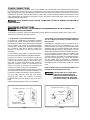
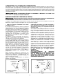
SHOCK HAZARD. DO NOT EXPOSE THE MACHINE TO RAIN OR OPERATE THE MACHINE IN
DAMP LOCAT I O N S .
Fig. A Fig. B
GROUNDED OUTLET BOX
CURRENT
CARRYING
PRONGS
GROUNDING BLADE
IS LONGEST OF THE 3 BLADES
GROUNDED OUTLET BOX
GROUNDING
MEANS
ADAPTER
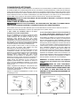
2. Grounded, cord-connected machines intended for
use on a supply circuit having a nominal rating less
than 150 volts:
If the machine is intended for use on a circuit that has an
outlet that looks like the one illustrated in Fig. A, t h e
machine will have a grounding plug that looks like the plug
illustrated in F i g . A. A temporary adapter, which looks like
the adapter illustrated in Fig. B, may be used to connect
this plug to a matching 2-conductor receptacle as shown in
Fig. B if a properly grounded outlet is not available. T h e
temporary adapter should be used only until a properly
grounded outlet can be installed by a qualified electrician.
The green-colored rigid ear, lug, and the like, extending
from the adapter must be connected to a permanent
ground such as a properly grounded outlet box. W h e n e v e r
t h e a d a p t e r i s used, it must be held in place with a metal
s c r e w.
N O T E : In Canada, the use of a temporary adapter is not
permitted by the Canadian Electric Code.
SHOCK HAZARD. IN A L L C A S E S , M A K E
C E R TAIN THAT THE RECEPTA C L E I N
Q U E S T I O N I S P R O P E R LY G R O U N D E D . I F
Y O U A R E N O T S U R E , H AV E A Q U A L I F I E D
E L E C T R I C I A N C H E C K T HE REC E P TA C L E .
1. All grounded, cord-connected machines:
In the event of a malfunction or breakdown, grounding
provides a path of least resistance for electric current to
reduce the risk of electric shock. This machine is equipped
with an electric cord having an equipment-grounding
conductor and a grounding plug. The plug must be plugged
into a matching outlet that is properly installed and
grounded in accordance with all local codes and
o r d i n a n c e s .
Do not modify the plug provided - if it will not fit the outlet,
have the proper outlet installed by a qualified electrician.
I m p r o p e r c o n n e c t i o n o f t h e e q u i p m e n t - g r o u n d i n g
c o n d u c t o r c a n r e s u l t i n r i s k o f e l e c t r i c s h o c k . T h e
conductor with insulation having an outer surface that is
green with or without yellow stripes is the equipment-
grounding conductor. If repair or replacement of the
electric cord or plug is necessary, do not connect the
equipment-grounding conductor to a live terminal.
Check with a qualified electrician or service personnel if the
g r o u n d i n g i n s t r u c t i o n s a r e n o t completely understood, o r i f
i n d o u b t a s t o w h e t h e r t h e m a c h i n e is properly grounded.
Use only 3-wire extension cords that have 3-prong
grounding type plugs and matching 3-c o n d u c t o r
receptacles that accept the machine’s plug, as shown in
Fig. A .
Repair or replace damaged or worn cord immediately.
POWER CONNECTIONS
Your machine is wired for 120 Volt, 60 HZ alternating current. Before connecting the machine to the power source,
make sure the switch is in the “OFF” position.
GROUNDING INSTRUCTIONS
SHOCK HAZARD. THIS MACHINE MUST BE GROUNDED WHILE IN USE TO PROTECT THE
OPERATOR FROM ELECTRIC SHOCK.

7
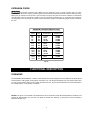
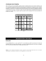
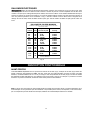
EXTENSION CORDS
Use proper extension cords. Make sure your extension cord is in good condition and is a 3-wire
extension cord which has a 3-prong grounding type plug and matching receptacle which will accept the machine’ s plug.
When using an extension cord, be sure to use one heavy enough to carry the current of the machine. An undersized
cord will cause a drop in line voltage, resulting in loss of power and overheating. Fig. C shows the correct gauge to
use depending on the cord length. If in doubt, use the next heavier gauge. The smaller the gauge number, the heavier
the cord.
Fig. C
MINIMUM GAUGE EXTENSION CORD
RECOMMENDED SIZES FOR USE WITH STAT I O N A R Y ELECTRIC MACHINES
A m p e r e Total Length Gauge of
R a t i n g Vo l t s of Cord in Feet Extension Cord
0 - 6 1 2 0
up to
2 5 18 AW G
0 - 6 1 2 0 2 5 - 5 0 16 AW G
0 - 6 1 2 0 5 0 - 1 0 0 16 AW G
0 - 6 1 2 0 1 0 0 - 1 5 0 14 AW G
6 - 1 0 1 2 0
up to
2 5 18 AW G
6 - 1 0 1 2 0 2 5 - 5 0 16 AW G
6 - 1 0 1 2 0 5 0 - 1 0 0 14 AW G
6 - 1 0 1 2 0 1 0 0 - 1 5 0 12 AWG
1 0 - 1 2 1 2 0
up to
2 5 16 AW G
1 0 - 1 2 1 2 0 2 5 - 5 0 16 AW G
1 0 - 1 2 1 2 0 5 0 - 1 0 0 14 AW G
1 0 - 1 2 1 2 0 1 0 0 - 1 5 0 12 AW G
1 2 - 1 6 1 2 0
up to
2 5 14 AW G
1 2 - 1 6 1 2 0 2 5 - 5 0 12 AW G
1 2 - 1 6 1 2 0 GREATER THAN 50 FEET NOT RECOMMENDED
F O R E W O R D
FUNCTIONAL DESCRIPTION
NOTICE: The photo on the manual cover illustrates the current production model. All other illustrations contained in the
manual are representative only and may not depict the actual color, labeling, or accessories, and are intended to
illustrate technique only.
The ShopMaster Model SM500 is a 4" Belt, 6" Disc Sander that comes equipped with a 5.2 AMP 120 Volt Single Phase
Induction Motor, a tilting table, a miter gauge, a backstop, a 4" x 36" 60-grit sanding belt, and a 6" 60-grit sanding disc.
You can mount the tilting table for use on either the belt or disc unit, and can operate the belt in the horizontal position,
the vertical position, or any position in between.

8
U N PACKING AND CLEANING
Carefully unpack the machine and all loose items from the shipping container(s). Remove the protective coating from all
unpainted surfaces. This coating may be removed with a soft cloth moistened with kerosene (do not use acetone, gasoline
or lacquer thinner for this purpose). After cleaning, cover the unpainted surfaces with a good quality household floor paste
wax.
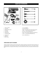
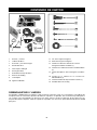
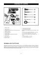
C A RTON CONTENTS
1
2
3
4
8
7
10
6
5
9
11
12
13
1. Motor and Base
2. Disc Table
3. Belt and Pulley Guard
4. Disc Plate
5. Dust Chute
6. Support Rod
7. Lower Disc Guard
8. Sanding Disc
9. Backstop
10. Miter Gauge
11. 1/8" Hex Wrench
12. 6mm Hex Wrench
13. M8 x 1.25 x 20mm Hex Socket Head Screw (3)
14. M6 x 1 x 30mm Cheese Head Screws (2)
15. 1/4-20 x 1/2" Hex Head Screw (1)
16. M5 x .08 x 10mm Pan Head Screw w/washer (3)
17. M4 x .7 x 12mm Sheet Metal Screw (3)
18. 5/16" Flat Washer (1)
14
15
16
17
18

9
A S S E M B LY
A S S E M B LY TOOLS REQUIRED
A S S E M B LY TIME ESTIMAT E
1/8" Hex Wrench (Supplied)
6 mm Hex Wrench (Supplied)
Phillips Screwdriver
Adjustable Wrench
Less than one hour
For your own safety, do not connect the machine to the power source until the machine is
completely assembled and you read and understand the entire instruction manual.
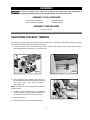
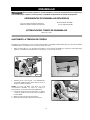
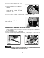
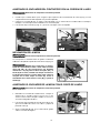
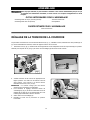
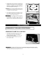
Your sander was shipped from the factory with the drive belt (A) Fig. 1 attached to both pulleys (B) and (C). Before
assembling the machine, check and adjust the belt tension.
1. Loosen the screw (D) Fig. 1 with the 6mm hex wrench, and move the sanding arm (E) to the vertical position to
expose belt tensioning screw (F) Fig. 2, and locknut (G).
ADJUSTING THE BELT TENSION
D
B
E
C
A
Fig. 1
Fig. 2
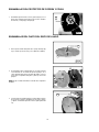
2. Check the belt tension by applying light pressure on
the belt halfway between the two pulleys.The belt has
the correct tension when you can deflect it
approximately 1/4".
NOTE: The belt does not require excessive tension to
function properly.
3. To adjust, loosen the locknut (A) Fig. 3, and tighten or
loosen the adjusting screw (B) with the supplied 6mm
hex wrench until the belt has the correct tension.
4. Tighten locknut (A).
5. Move the sanding arm to the horizontal position.
Fig. 3
F
G
A
B

10
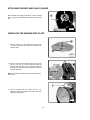
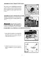
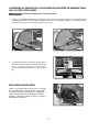
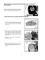
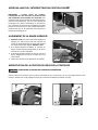
Attach the belt and pulley guard (A) Fig. 4 to the machine
base using the two M6x1x30mm cheese head screws
(B).
1. Turn the 1/4-20 x 1/4" hex socket set screw (A) Fig.
5 counter-clockwise until it clears the hole (B) in the
sanding plate.
2. Align the flat of the drive shaft with the set screw (A)
Fig. 6 in the hub of the plate (B) and install the
sanding disc plate (B) on the drive shaft. Slide the
plate (B) on the shaft (C) until the plate surface and
the shaft are flush.
3. Use the supplied 1/8" hex wrench (A) Fig. 7 to
tighten the set screw, located in the slot in the back
of belt and pulley guard.
ATTACHING THE BELT AND PULLEY GUARD
Fig. 4
B
A
INSTALLING THE SANDING DISC PLATE
A
B
Fig. 5
Note: Do not allow the shaft to extend past the surface
of the plate.
Fig. 6
Fig. 7
A
B
C
A

11
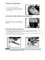
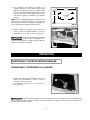
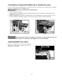
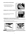
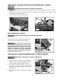
1. Clean the sanding disc plate (A) Fig. 8.
2. Peel the backing from sanding disc and press the
disc (B) firmly into position all the way around the
sanding plate (Fig. 8).
Install the lower cover (A) Fig. 9 on the belt and pulley
guard, using the three M4 x .7 x 12mm sheet metal
screws (B).
1. Thread an M8 x 1.25 x 20mm hex socket head screw (A) Fig. 10 partially into the hole in the base of the sander.
Insert the rod (B) into the hole. Align the flat of the rod (B) with the screw (A). Tighten the screw (A).
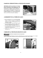
2. Slide the table assembly (C) Fig. 11 on the rod (B).
3. Thread an M8 x 1.25 x 20mm hex socket head screw (A) Fig. 11 into the hole in the table support bracket. Align the
flat on the rod (B) with the screw (A). Tighten the screw (A).
To avoid trapping the work or fingers between the table and the sanding disc, the table edge (E)
Fig. 11 should be positioned a maximum of 1/16" away from the sanding disc (F). Loosen the
screw (A) and adjust the table accordingly.
ATTACHING THE SANDING DISC
B
A
Fig. 8
ATTACHING THE LOWER COVER FOR THE SANDING DISC
B
A
INSTALLING THE DISC SANDER TABLE
Fig. 9
Fig. 10
Fig. 11
A B
A
B
C
F
E

12
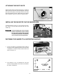
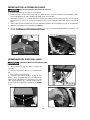
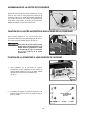
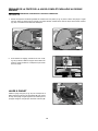
Align the three holes in the dust chute (A) Fig. 12 with the
three holes in the left side of the sanding base. Insert the
pan head screw (B) Fig.12 through the hole in the dust
spout and thread it into the taped hole in the sander
base. Repeat this process for the two remaining holes.
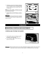
FASTENING THE SANDER TO A SUPPORTING SURFACE
1. To use your sander in a permanent location, fasten it
securely to a firm supporting surface, such as a stand
or workbench. Use the four holes, three of which are
shown at (A) Fig. 14.
2. The diagram in Fig. 15 illustrates the size and
center-to-center distance of the holes to be drilled in
the stand or workbench.
ATTACHING THE DUST CHUTE
INSTALLING THE BACKSTOP ON THE SANDING ARM
Install the backstop (A) Fig. 13 on the sanding arm using
the 1/4-20 x 1/2" hex head screw (B) and 5/16" flat
washer (C).
To avoid trapping the work or fingers
between the backstop and the sanding
belt, the edge of the backstop (D) Fig.
13 should be positioned a maximum of
1/16" away from the sanding belt (E).
A
B
A
C
B
D
E
Fig. 12
Fig. 13
A
Fig. 14
Fig. 15

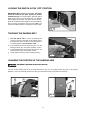
13
3. Alternately, you can secure the sander by fastening it
to a mounting board 18" x 24" or larger. The diagram
in Fig. 16 shows the size and center-to-center
distance of the holes that you will need to drill in the
mounting board.
N O T E : For proper stability, countersink the holes
underneath the mounting board so that the screw heads
are flush with bottom surface.
4. Securely clamp the mounting board to a stand or
workbench using 2 or more “‘C” clamps, as shown in
Fig. 17.
Secure the machine base to the supporting
surface. If there is any tendency for the stand or workbench
to move during operation, the stand or workbench must be
fastened to the floor.
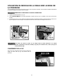
1. The on/off switch (A) Fig. 18 is located on the front
of the sander. To turn the machine “ON”, move
the switch up to the “ON” position.
2. To turn the machine “OFF”, move the switch (A)
down to the “OFF” position.
O P E R AT I O N
O P E R AT I O N A L CONTROLS AND ADJUSTMENTS
Make sure that the switch is in the “OFF” position before plugging in the power cord. In the event of
a power failure, move the switch to the “OFF” position. An accidental start-up can cause injury.
A
STARTING AND STOPPING THE SANDER
Fig. 16
Fig. 17
Fig. 18
l l
l l
18 MIN
5-1/2"
15-1/2"
24 MIN
3/8" DIAMETER
(4) HOLES

14
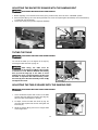
1. Turn the switch “ON” to see if the sanding belt
moves to one side or the other on the sanding drums.
If the belt rides on the center of the sanding drums, it
is tracking properly. Turn the switch “OFF”.
2. If the sanding belt moves toward the disc, turn the
tracking knob (A) Fig. 20 counter-clockwise 1/4 turn.
3. If the sanding belt moves away from the disc, turn the
tracking knob (A) Fig. 20 clockwise 1/4 turn.
4. Check again to see if the belt is tracking properly.
IMPORTANT: When the tool is not in use, the switch
should be locked in the “OFF” position to prevent
unauthorized use. To lock the machine, grasp the switch
toggle (A) and pull it out of the switch (Fig. 19). With the
switch toggle (A) removed, the switch will not operate.
However, should the switch toggle be removed while the
saw is running, the machine can be turned “OFF,” but
cannot be restarted without re-inserting the switch toggle.
LOCKING THE SWITCH IN THE “OFF” POSITION
Fig. 19
TRACKING THE SANDING BELT
Fig. 20
CHANGING THE POSITION OF THE SANDING ARM
You can use the sanding arm (A) in the horizontal position (Fig. 21), the vertical position (Fig. 22), or any angle in
between. Loosen the screw (B), position the arm (A) to the desired angle, and tighten the screw (B).
DISCONNECT MACHINE FROM POWER SOURCE.
A
A
B
A
B
A
Fig. 21
Fig. 22

15
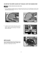
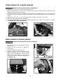
1. Before adjusting, move the belt tension lever (A) Fig. 23 all the way to the left to the "TIGHTEN" position.
2. Place a square (B) Fig. 24 on the sanding belt with one end of the square against the backstop. See if the backstop
is square with the sanding belt.
3. Loosen the screw (C) Fig. 24 and adjust the backstop.
After tilting, the table must be
repositioned on the support rod (B) Fig. 25 to provide
a maximum of 1/16" distance between the sanding
disc (C) and the edge (D) of the table to avoid
trapping the work or fingers between the disc and
the table. To reposition the table assembly, loosen
the screw (E), move the table assembly on the rod (B)
and tighten the screw.
1. Use a combination square with one end on the table
and the other end against the sanding disc (Fig. 26).
See if the table is 90 degrees to the disc.
2. To adjust, loosen the table lock knob (A) Fig. 26,
move the table square with the disc and tighten the
lock knob (A).
3. Adjust the pointer (B) Fig. 26 to the "0" degree mark
on the angle scale.
ADJUSTING THE BACKSTOP SQUARE WITH THE SANDING BELT
DISCONNECT MACHINE FROM POWER SOURCE.
A
Fig. 23
Fig. 24
B
C
TILTING THE TABLE
You can tilt the table up to 45 degrees to the right by
loosening the table lock knob (A) Fig. 25.
DISCONNECT MACHINE FROM POWER SOURCE.
Fig. 25
A
E
B
C D
ADJUSTING THE TABLE SQUARE WITH THE SANDING DISC
DISCONNECT MACHINE FROM POWER SOURCE.
A
B
Fig. 26

16
2. To adjust, loosen the three screws (B) Fig. 29 that
fasten the table to the table mounting bracket and
trunnion. Adjust the table accordingly - then tighten
the three screws (B).
MITER GAUGE
Use the miter gauge (A) Fig. 30 on the disc table. You can
rotate the miter gauge body right or left for angle or miter
sanding by loosening the lock knob (B), rotating the miter
gauge body, and tightening the lock knob.
1. Place an adjustable combination square on the table with the part (A) Fig. 27 in the miter gauge slot (B) to check
the distance from the slot to the sanding disc. Check the other side of the disc in the same manner (Fig. 28). The
distances should be the same.
ADJUSTING THE MITER GAUGE SLOT PARALLEL WITH THE SANDING DISC
DISCONNECT MACHINE FROM POWER SOURCE.
A
B
Fig. 27
Fig. 28
B
A
B
Fig. 29
Fig. 30

17
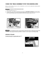
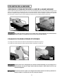
When you use the sanding arm (A) Fig. 31 in the vertical position, you can move the complete table assembly (B) from
the disc unit to the belt unit.
Two holes are provided in the base casting to store the
two wrenches (A) Fig. 33, supplied with the sander.
USING THE TABLE ASSEMBLY WITH THE SANDING ARM
DISCONNECT MACHINE FROM POWER SOURCE.
1. Remove the backstop (C) Fig. 31.
2. Thread the M8 x 1.25 x 20mm hex socket head screw (D) Fig. 31 ONLY PART OF THE WAY into the base casting.
3. Loosen the screw (E) Fig. 31, and remove the table assembly (B) from the disc unit. Insert the bar (F) into the hole
(G) on the belt unit. Align the flat on the shaft with the screw in the casting and tighten the screw.
Fig. 31
C
A
D
G
E
F
B
To avoid trapping the work or fingers between the backstop and the sanding belt, the edge of the
table (A) Fig. 32 should be positioned a maximum of 1/16" away from the sanding belt (B).
Fig. 32
B
A
WRENCH STORAGE
Fig. 33
A

18
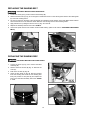
1. Loosen the screw (A) Fig. 34 and remove the backstop (B).
2. Slide the tension lever (C) Fig. 35 to the right to release the tension on the sanding belt. Remove the sanding belt
(D) from both sanding drums.
3. An arrow is printed on the back of the sanding belt to indicate the travel direction of the belt. Make certain that this
arrow and the arrow on the machine match. Slide the new sanding belt over both sanding drums.
4. Apply belt tension by sliding the tension lever (C) Fig. 35 to the left.
5. Replace the backstop that was removed in STEP 2.
6. Connect the power source to the sander. Check the belt tracking. (Refer to the section "TRACKING THE SANDING
BELT").
REPLACING THE SANDING BELT
DISCONNECT MACHINE FROM POWER SOURCE.
Fig. 34
A
Fig. 35
B
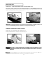
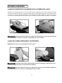
REPLACING THE SANDING DISC
DISCONNECT MACHINE FROM POWER SOURCE.
1. Loosen the screw (A) Fig. 36 to remove the table
assembly (B).
2. Remove the three screws (B) Fig. 37. Remove the
cover (D).
4. Peel off the old disc (E) Fig. 38.
5. Clean the disc plate (F) Fig 38. Peel the backing
from new sanding disc. Press the new sanding disc
firmly into position on disc plate (F) and replace the
lower cover and table assembly removed in STEPS
1 and 2.
D
C
A
B
D
B
E
F
Fig. 36
Fig. 37
Fig. 38

19
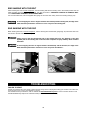
M A C H I N E U S E
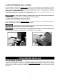
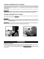
SURFACING OR EDGE SANDING WITH THE SANDING BELT
Always use the backstop (A) Figs. 39 and 40 when surface-sanding (Fig. 39) or when edge sanding Fig. 40. Hold the
workpiece firmly and keep your fingers away from the sanding belt. Keep the end of the workpiece against the backstop
and move the workpiece evenly across the sanding belt. Apply only enough pressure to allow the sanding belt to remove
material. Use extra caution when sanding very thin pieces.
Fig. 39
Fig. 40
A
A
To avoid trapping the work or fingers between the backstop and the sanding belt, the edge of the
table should be positioned a maximum of 1/16" away from the sanding belt .
Sanding inside curves with the sanding belt is illustrated in Fig. 41.
Sanding outside curves with the sanding disc is illustrated in Fig. 42.
SANDING INSIDE AND OUTSIDE CURVES
Fig. 42
Fig. 41
Always sand on the left (downward) side of the sanding disc (Fig. 41). Sanding on the right
(upward) side of the sanding disc could cause the workpiece to fly up suddenly which could be
hazardous.
To avoid trapping the work or fingers between the backstop and the abrasive, the edge of the
table should be positioned a maximum of 1/16" away from the abrasive .

20
END SANDING WITH THE BELT
When sanding the ends of wide workpieces, use the sanding belt with the sanding arm in the vertical position and the
table assembly moved to the sanding belt (Fig. 43). See the sections “CHANGING POSITION OF SANDING ARM”
and “USING TABLE ASSEMBLY WITH SANDING BELT”.
For more accurate work, use the supplied miter gauge to move the work evenly across the sanding belt (Fig. 43).
END SANDING WITH THE DISC
When sanding the ends of narrow workpieces, use the sanding disc and the miter gauge (Fig. 44). Move the work from
the center to the left side of the sanding disc.
To avoid trapping the work or fingers between the backstop and the sanding belt, the edge of the
table should be positioned a maximum of 1/16" away from the sanding belt .
Always sand on the left (downward) side of the sanding disc (Fig. 44). Sanding on the right
(upward) side of the sanding disc could cause the workpiece to fly up suddenly which could be
hazardous.
To avoid trapping the work or fingers between the backstop and the abrasive, the edge of the
table should be positioned a maximum of 1/16" away from the abrasive .
Fig. 43
Fig. 44
T R O U B L E S H O O T I N G
FAILURE TO STA R T
Should your machine fail to start, check to make sure the prongs on the cord plug are making good contact in the outlet. A l s o ,
check for blown fuses or open circuit breakers in the line.
For assistance with your machine, visit our website at www.deltamachinery.com for a list of service centers or call
the DELTA Machinery help line at 1-800-223-7278 (In Canada call 1-800-463-3582).
La page est en cours de chargement...
La page est en cours de chargement...
La page est en cours de chargement...
La page est en cours de chargement...
La page est en cours de chargement...
La page est en cours de chargement...
La page est en cours de chargement...
La page est en cours de chargement...
La page est en cours de chargement...
La page est en cours de chargement...
La page est en cours de chargement...
La page est en cours de chargement...
La page est en cours de chargement...
La page est en cours de chargement...
La page est en cours de chargement...
La page est en cours de chargement...
La page est en cours de chargement...
La page est en cours de chargement...
La page est en cours de chargement...
La page est en cours de chargement...
La page est en cours de chargement...
La page est en cours de chargement...
La page est en cours de chargement...
La page est en cours de chargement...
La page est en cours de chargement...
La page est en cours de chargement...
La page est en cours de chargement...
La page est en cours de chargement...
La page est en cours de chargement...
La page est en cours de chargement...
La page est en cours de chargement...
La page est en cours de chargement...
La page est en cours de chargement...
La page est en cours de chargement...
La page est en cours de chargement...
La page est en cours de chargement...
La page est en cours de chargement...
La page est en cours de chargement...
La page est en cours de chargement...
La page est en cours de chargement...
La page est en cours de chargement...
La page est en cours de chargement...
La page est en cours de chargement...
La page est en cours de chargement...
La page est en cours de chargement...
La page est en cours de chargement...
La page est en cours de chargement...
La page est en cours de chargement...
-
 1
1
-
 2
2
-
 3
3
-
 4
4
-
 5
5
-
 6
6
-
 7
7
-
 8
8
-
 9
9
-
 10
10
-
 11
11
-
 12
12
-
 13
13
-
 14
14
-
 15
15
-
 16
16
-
 17
17
-
 18
18
-
 19
19
-
 20
20
-
 21
21
-
 22
22
-
 23
23
-
 24
24
-
 25
25
-
 26
26
-
 27
27
-
 28
28
-
 29
29
-
 30
30
-
 31
31
-
 32
32
-
 33
33
-
 34
34
-
 35
35
-
 36
36
-
 37
37
-
 38
38
-
 39
39
-
 40
40
-
 41
41
-
 42
42
-
 43
43
-
 44
44
-
 45
45
-
 46
46
-
 47
47
-
 48
48
-
 49
49
-
 50
50
-
 51
51
-
 52
52
-
 53
53
-
 54
54
-
 55
55
-
 56
56
-
 57
57
-
 58
58
-
 59
59
-
 60
60
-
 61
61
-
 62
62
-
 63
63
-
 64
64
-
 65
65
-
 66
66
-
 67
67
-
 68
68


Delta 491836-00 Manuel utilisateur
- Taper
- Manuel utilisateur
- Ce manuel convient également à
dans d''autres langues
- English: Delta 491836-00 User manual
- español: Delta 491836-00 Manual de usuario
- português: Delta 491836-00 Manual do usuário
Documents connexes
-
Delta 31-695 Manuel utilisateur
-
-
-
-
-
-
-
-
-
Autres documents
-
Black & Decker BDSA100 Manuel utilisateur
-
Skil 3375-01 Manuel utilisateur
-
DeWalt 31-260X Manuel utilisateur
-
Ryobi BD4601 Mode d'emploi
-
-
-
-
General International BD7004 Manuel utilisateur
-
-