La page est en cours de chargement...

SB-2-855-D (1/2018)1 / 16www.carlisleft.com
Technical Bulletin
SRi Pro range of Gravity Spray Guns
for spot repairs and small areas
IMPORTANT! DO NOT DESTROY
It is the Customer's responsibility to have all operators and service personnel read and understand this manual.
Contact your local DeVilbiss representative for additional copies of this manual.
READ ALL INSTRUCTIONS BEFORE OPERATING THIS DEVILBISS PRODUCT.
EN
SERVICE MANUAL

SB-2-855-D (1/2018)2 / 16www.carlisleft.com
Table of Contents
Topic Page
EC Declaration of Conformity ................................................ 3
Operational Description .................................................... 3
Construction Features ...................................................... 4
Materials of Construction ................................................... 4
Specifications & Technical Data .............................................. 4
Safety Precautions ......................................................... 5
Parts List ................................................................. 6
Exploded Parts View ....................................................... 7
Installation, Operation, Preventive Maintenance & Cleaning, Spray Gun Lubrication .. 8
Parts Replacement/Maintenance ............................................. 9-13
A. Servicing Air Valve ................................................. 9
B. Replacing Air Valve ................................................. 10
C. Needle Packing, Spreader Valve Assembly .............................. 11
D. Replacing Separator Seal ............................................ 12
E. Chart 1 – Air Caps, Chart 2 – Fluid Nozzles & Fluid Needles ................ 13
Troubleshooting Possible Problems in Operation ............................... 14, 15
Accessories .............................................................. 16
Warranty ................................................................. 16

SB-2-855-D (1/2018)3 / 16www.carlisleft.com
EC Declaration of Conformity
Operational Description
This SRi PRO Spray Gun is a professional quality gun designed with both high volume, low pressure (HVLP)
technology or Trans-Tech
®
technology. HVLP Technology reduces overspray and limits air cap pressure
to 0.7 bar (10 psi) (complies with rules issued by SCAQMD and other air quality authorities). Trans-Tech
technology, when tested under recommended conditions with automotive refinishing materials, has been
found to exceed 65% transfer efficiency.
IMPORTANT: These Sprayguns are suitable for use with both waterbased and solvent based coating
materials. These guns are not designed for use with highly corrosive and/or abrasive materials and if
used with such materials it must be expected that the need for cleaning and/or replacement of parts will
be increased. If there is any doubt regarding the suitability of a specific material, contact your DeVilbiss
Distributor or DeVilbiss direct.
NOTE: This gun is not to be used with halogenated hydrocarbon solvents or cleaning agents such as
1,1,1,-Trichloroethane or methylene chloride. These solvents can react with the aluminium components
used in this gun and cup. The reaction can become violent and lead to an equipment explosion.
Dave Smith
Bournemouth,BH11 9LH,UK
Product Description/Object of Declaration:
Solvent and Water based Materials
Zone 1 / Zone 2Suitable for use in hazardous area:
This Product is designed for use with:
SRi PRO
The object of the declaration described above is in conformity with the relevant Union harmonisation
legislation:
This Declaration of Conformity
/incorporation is issued under the sole
responsiblility of the manufacturer:
Carlisle Fluid Technologies UK Ltd.
Ringwood Road,
Bournemouth, BH11 9LH. UK
EU Declaration of Conformity
Protection Level: II 2 G X
Notified body details and role: TRAC Global Ltd (0891)
Lodging of Technical file
11-Jul-16
Signed for and on behalf of
Carlisle Fluid Technologies UK Ltd:
Machinery Directive 2006/42/EC
ATEX Directive 2014/34/EU
by complying with the followi
ng statutory documents and harmonized standards:
EN ISO 12100:2010 Safety of Machinery - General Principles for Design
BS EN 1953:2013 Atomising and spraying equipment for coating materials - Safety requirements
EN 1127-1:2011 Explosive atmospheres - Explosion prevention - Basic concepts
EN 13463-1:2009 Non electrical equipment for use in potentially explosive atmospheres - Basic methods and requirements
Providing all conditions of safe use / installation stated within the product manuals have been complied with and also
installed in accordance with any applicable local codes of practice.
Director of Sales (EMEA)

SB-2-855-D (1/2018)4 / 16www.carlisleft.com
MATERIALS OF CONSTRUCTION
Gun Body Anodized aluminium
Air Cap Nickel plated brass
Fluid Nozzle, Fluid Needle, Fluid Inlet, Trigger Stud Stainless steel (303)
Springs, Clips, Screws Stainless steel (303)
Seals, Gaskets Solvent resistant
Trigger Chrome plated steel
Air Inlet, Body Bushing, Spreader Valve Body, Air Valve Nut,
Air Cap Retaining Ring, Knobs
Chrome plated brass
Air Valve Assembly Stainless steel (303), HPDE
SPECIFICATIONS & TECHNICAL DATA
Air Supply Connection Universal 1/4" BSP and 1/4" NPS male
Maximum Static Air Inlet Pressure P1 = 175 psi (12 bar)
Nominal Gun Air Inlet Pressure for HVLP (HS1) and
Trans-Tech
®
(TS1) with gun triggered
29 psi (2.0 bar)
Fluid Supply Connection 7/16 – 14 UNC
Service Temperature 32 to 104°F (0 to 40°C)
Gun Weight (gun only)
(with cup)
15.0 oz (425 g)
17.1 oz (485 g)
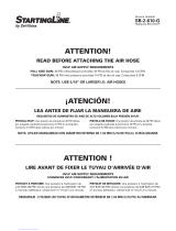
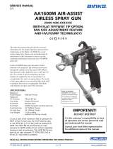
CONSTRUCTION FEATURES
1
Air Cap
(nickel plated brass for long durability)
2
Air Cap Retaining Ring
(allows easy rotation of air cap)
3
Fluid Nozzle
(ideal for automotive topcoat systems)
4
Fluid Needle
(grooved stem for easy removal)
5
Fluid Inlet (7/16” – 14 UNC thread) – accepts
DeVilbiss SRI cup systems
6
Air Inlet
(universal thread, accepts G 1/4 & 1/4 NPS)
7
Self Adjusting Needle Packing
(for trouble free operation)
8 Trigger (ergonomic for comfort)
9
Trigger Stud & Screw
(easy replacement design)
10
Fan Air Adjustment
(stepless regulation for fan to round spray)
11
Fluid Adjustment
(stepless regulation of fluid volume)
12
Interchangeable Color ID System
(4 colored rings supplied)
13
Anodized, forged aluminium gun body
(ergonomic, good looking & durable, easy
to clean)
14 125cc Acetal Cup (easy clean, anti-static)
15 Cup Lid with Drip Free Vent (avoid drips)
16
Air Valve (design offers low pull force & low
pressure drop)
17
Gun acceptable for waterborne and solvent
borne applications
18
Gun can be used with DeVilbiss disposable
cups

SB-2-855-D (1/2018)5 / 16www.carlisleft.com
CAUTION
Important information that tells how
to prevent damage to equipment,
or how to avoid a situation that may
cause minor injury.
NOTE
Information that you should pay special
attention to.
SAFETY PRECAUTIONS
This manual contains information that is important for you to know and understand. This information relates to USER SAFETY and
PREVENTING EQUIPMENT PROBLEMS. To help you recognize this information, we use the following symbols. Please pay particular
attention to these sections.
Important safety information – A hazard
that may cause serious injury or loss
of life.
The following hazards may occur during the normal use of this equipment.
Please read the following chart before using this equipment.
HAZARD CAUSE SAFEGUARDS
Fire
Solvent and coatings can be highly flammable or
combustible especially when sprayed.
Adequate exhaust must be provided to keep air free of
accumulations of flammable vapors.
Smoking must never be allowed in the spray area.
Fire extinguishing equipment must be present in the spray
area.
Solvent Spray
During use and while cleaning and flushing,
solvents can be forcefully expelled from fluid
and air passages. Some solvents can cause
eye injury.
Wear eye protection.
Inhaling Toxic Substances
Certain materials may be harmful if inhaled, or if
there is contact with the skin.
Follow the requirements of the Safety Data Sheet supplied by
your coating material manufacturer.
Adequate exhaust must be provided to keep the air free of
accumulations of toxic materials.
Use a mask or respirator whenever there is a chance of inhal-
ing sprayed materials. The mask must be compatible with the
material being sprayed and its concentration. Equipment must
be as prescribed by an industrial hygienist or safety expert,
and be NIOSH approved.
Explosion Hazard -
Incompatible Materials
Halogenated hydrocarbon solvents
- for example; methylene chloride and 1,1,1, -
Trichloroethane are not chemically compatible
with the aluminum that might be used in many
system components. The chemical reaction
caused by these solvents reacting with aluminum
can become violent and lead to an equipment
explosion.
Guns with stainless steel internal passageways may be used
with these solvents. However, aluminum is widely used in
other spray application equipment - such as material pumps,
regulators, valves, and this gun and cup. Check all equip-
ment items before use and make sure they can also be used
safely with these solvents. Read the label or data sheet for
the material you intend to spray. If in doubt as to whether or
not a coating or cleaning material is compatible, contact your
material supplier.
General Safety
Improper operation or maintenance of
equipment.
Operators should be given adequate training in the safe use
and maintenance of the equipment (in accordance with the
requirements of NFPA-33, Chapter 15). Users must comply
with all local and national codes of practice and insurance
company requirements governing ventilation, fire precautions,
operation, maintenance, and housekeeping. These are OSHA
Sections 1910.94 and 1910.107 and NFPA-33.
Cumulative Trauma
Disorders ("CTD's")
CTD's, or musculoskeletal
disorders, involve damage
to the hands, wrists,
elbows, shoulders, neck,
and back. Carpal tunnel
syndrome and tendonitis
(such as tennis elbow or
rotator cuff syndrome) are
examples of CTD's.
Use of hand tools may cause cumulative trauma
disorders ("CTD's").
CTD's, when using hand tools, tend to affect the
upper extremities. Factors which may increase
the risk of developing a CTD include:
1. High frequency of the activity.
2. Excessive force, such as gripping, pinching,
or pressing with the hands and fingers.
3. Extreme or awkward finger, wrist, or arm
positions.
4. Excessive duration of the activity.
5. Tool vibration.
6. Repeated pressure on a body part.
7. Working in cold temperatures.
CTD's can also be caused by such activities as
sewing, golf, tennis, and bowling, to name a few.
Pain, tingling, or numbness in the shoulder, forearm, wrist,
hands, or fingers, especially during the night, may be
early symptoms of a CTD. Do not ignore them. Should you
experience any such symptoms, see a physician immediately.
Other early symptoms may include vague discomfort in the
hand, loss of manual dexterity, and nonspecific pain in the
arm. Ignoring early symptoms and continued repetitive use of
the arm, wrist, and hand can lead to serious disability. Risk is
reduced by avoiding or lessening factors 1-7.

SB-2-855-D (1/2018)6 / 16www.carlisleft.com
PARTS LIST
REF.
NO.
DESCRIPTION PART NO. QTY.
1 Air Cap Retaining Ring 1
2 Slip Ring 1
3 Air Cap 1
5 Retaining Ring Seal SRI-35-K5 1
6 Air Cap & Ring See chart 1, p13 1
8 Fluid Nozzle See chart 2, p13 1
9 Separator SRIPRO-2-K5 1
12* Body Bushing Seal 1
13 Body Bushing 1
14 Body Bushing & Seal 702728 1
15 Fluid Needle See chart 2, p13 1
16* Needle Spring 1
17* Needle Spring Pad 1
18 Fluid Adjusting Knob 1
19
Fluid Adjusting Knob,
Spring & Pad Kit
PRO-3-K 1
20* Retaining Clip 1
21 Spreader Valve Body 1
22* Spreader Valve Seal 2
23
Spreader Valve Adjusting
Knob
1
24* Valve Pin 1
25 Spreader Valve Assembly SRIPRO-401-K 1
26* Needle Packing 1
27* Packing Spring 1
28 Packing Nut 1
29
Packing, Spring &
Packing Nut Kit
702731 1
30 Air Valve Body 1
31 Air Valve Cage 1
REF.
NO.
DESCRIPTION PART NO. QTY.
32 Air Valve Poppet 1
33 Air Valve Spring 1
34 Air Valve Spring Pad 1
35 Air Valve Seal SN-34-K5 1
36 Air Valve Assembly 702732 1
37*
Trigger Stud Screw
(T20 Star)
1
38 Trigger 1
39* Trigger Stud 1
40 Trigger, Stud & Screw Kit SN-42-K 1
41 Air Inlet SN-40-K 1
42
Color ID Ring Kit
(4 colors)
702735 1
43 Airflow Valve PRO-404-K 1
44 Circlip 1
45 Wrench 1
46
Air Valve Service Tool
(included in 702732)
1
47 Air Flow Valve Knob 1
SERVICE PARTS
Spray Gun Repair Kit
(includes items marked *)
702736
Seal & Pin Kit, kit of 5
(items 20, 22 and 24)
GTI-428-K5
For accessories, see page 16

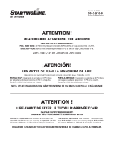
SB-2-855-D (1/2018)7 / 16www.carlisleft.com
k
Fluid Nozzle
(Torque to 80-90 in-lbs)
k
A
A
B
Fig. B
Fig. A
Views showing correct
Air Cap/Retaining Ring assembly.

SB-2-855-D (1/2018)8 / 16www.carlisleft.com
INSTALLATION
For maximum transfer efficiency,
do not use more pressure than is
necessary to atomize the material
being applied. NOTE: when using the
HS1, HVLP setup do not exceed 29.0
psi (2 bar) inlet pressure. This will
insure HVLP compliance by limiting
air cap pressure to 10 psi (0.7 bar).
1. Connect the gun to a clean,
moisture and oil free air supply
using a conductive hose.
NOTE
Install an air gauge at the
gun handle. When gun
is triggered on, adjust
regulated pressure to 29.0
psi (2.0 bar). Do not use
more pressure than is
necessary to atomize the
material being applied.
Excess pressure will create
additional overspray and
reduce transfer efficiency.
NOTE
If an air adjusting valve
is used at the gun inlet,
use DeVilbiss model HAV-
512. Some competitive
adjusting valves have
significant pressure drop
that can adversely affect
spray performance. The
DeVilbiss model HAV-512
has minimal pressure drop,
which is important for HVLP
spraying.
2. Attach the gravity feed cup to the
material inlet.
NOTE
Before using the gun, flush
it with solvent to ensure that
the fluid passages are clean.
OPERATION
1. Mix coating material to
manufacturer’s instructions.
2. Strain the material.
3. Fill the cup to no more than 1/2
inch from the top of the cup. DO
NOT OVERFILL.
4. Attach Cup Lid. Make sure that the
cup lid vent hole is clear.
5. Turn fluid adjusting knob (18)
clockwise to prevent fluid needle
movement.
6. Turn spreader valve adjusting knob
(23) counter clockwise to fully
open.
7. Adjust inlet air pressure to 29.0 psi
(2.0 bar).
8. Turn fluid adjusting knob counter
clockwise until first thread shows.
9. Test spray. If the finish is too dry,
reduce airflow by reducing air inlet
pressure.
10. If finish is too wet, reduce fluid
flow by turning fluid adjusting
knob (18) clockwise. If atomization
is too coarse, increase inlet air
pressure. If too fine, reduce inlet
pressure.
11. The pattern size can be reduced
by turning spreader valve knob
(23) clockwise.
12. Hold gun perpendicular to surface
being sprayed. Arcing or tilting
may result in uneven coating.
13. The recommended spray distance
is 3-6 in (75-150 mm).
14. Spray edges first. Overlap each
stroke a minimum of 75%. Move
gun at a constant speed.
15. Always turn off air supply and
relieve pressure when gun is not
in use.
PREVENTIVE MAINTENANCE
& CLEANING
To clean air cap and fluid nozzle,
brush exterior with a stiff bristle
brush. If necessary to clean cap holes,
use a broom straw or toothpick if
possible. If a wire or hard instrument
is used, extreme care must be used
to prevent scratching or burring of
the holes which will cause a distorted
spray pattern.
To clean fluid passages, remove
excess material from cup, then flush
with gun wash solution. Wipe the
gun exterior with a dampened cloth.
Never completely immerse in any
solvent or cleaning solutions as this
is detrimental to the lubricants and
life of the spray gun.
NOTE
When replacing the fluid
nozzle or fluid needle,
replace both at the same
time. Using worn parts
can cause fluid leakage.
See page 13, Chart 2. Also,
replace the needle packing
at this time. Torque the fluid
nozzle to 80-90 in-lbs (9-10
Nm). Do not over tighten.
CAUTION
To prevent damage to fluid
nozzle (8) or fluid needle
(15), be sure to either 1) pull
the trigger and hold while
tightening or loosening the
fluid nozzle, or 2) remove
fluid adjusting knob (18)
to relieve spring pressure
against needle collar.
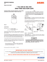
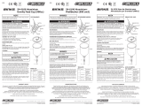
SPRAY GUN LUBRICATION
Daily, apply a drop of spray gun lube
at trigger bearing stud (39) and the
stem of the air valve (32). The shank
of the fluid needle (15) where it enters
the packing nut (28) should also be
oiled. Make sure the retaining ring (1)
threads are clean and free of foreign
matter. Before assembling retaining
ring to spray gun, clean the threads
thoroughly, then add two drops of
spray gun lube to threads. The fluid
needle spring (16) should be coated
with a very light grease. For best
results, lubricate the points indicated,
daily.
A. Trigger Points
B. Packing
C. Adjusting Valves
D. Gun/Air Cap Threads
E. Air Valve Cartridge
A
B
C
E
D
A

SB-2-855-D (1/2018)9 / 16www.carlisleft.com
PARTS REPLACEMENT/MAINTENANCE
AIR VALVE INSTRUCTIONS
Servicing Air Valve
Reasons to service air valve:
A) Air valve not functioning correctly (may need
cleaning).
B) Routine maintenance.
C) Air leaks (advise replacement, see p10)
1. Remove trigger using a Star T20 key. (See fig 1 & 2)
2. Unscrew air valve using a (14 mm wrench. (See
fig 3)
3. Remove air valve by gripping stem. (See fig 4)
4. Remove spring with spring pad. (See fig 5)
5. DO NOT REMOVE REAR SEAL (35) FROM GUN
BODY. (See fig 6)
6. DO NOT REMOVE PLASTIC CAGE FROM AIR VALVE
BODY AS THIS MAY DAMAGE THE CAGE. (See fig 7)
7. CLEAN
a. Remove all paint build up. (See fig 8)
b. The 4 poppet holes must be clear. (See fig 9)
c. Stem must be free to float in poppet. (See fig 10)
d. Stem must slide through cage bore with slight
resistance (due to seal).
e. Rear seal must look clean and in position in the
bore. (See fig 6)
f. If any of the above cannot be rectified, replace the
air valve. (See Replacing Air Valve, p10)
8. Replace spring ensuring the end with the plastic
bearing pad goes in first. (See fig 5)
9. Insert air valve assembly into gun and carefully feed
over the spring and through the rear seal. (See fig 11)
10. Tighten air valve assembly using fingers first, and
then tighten with a 14mm wrench. (See fig 12)
11. Replace trigger. (See figs 2 & 1)
12. If there is an air leak through the gun, the air valve
may need replacing. (See Replacing Air Valve)

SB-2-855-D (1/2018)10 / 16www.carlisleft.com
PARTS REPLACEMENT/MAINTENANCE
AIR VALVE INSTRUCTIONS
Replacing Air Valve
Reasons to replace air valve:
A) Air leak through the gun.
B) Air valve not operating correctly.
1. Remove trigger using a Star (T20) key. (See figs 13
& 14)
2. Unscrew air valve using a 14 mm wrench. (See fig 15)
3. Remove air valve by gripping the stem. (See fig 16)
4. Remove spring with spring pad. (See fig 17)
5. Hook out rear seal using Service Tool (46). (See figs
18 & 19)
6. Clean air valve bores in gun body with a brush.
7. Place new rear seal onto Service tool (46); grooves
must fit in service tool form. (See fig 20)
8. Push rear seal firmly into hole up to shoulder, using
Service tool. (See figs 21 & 22)
9. Insert new spring, ensuring the end with the plastic
bearing pad goes in first. (See fig 17)
10. Insert air valve assembly into gun and carefully feed
over the spring and through the rear seal. (See fig
23)
11. Tighten air valve assembly using fingers first, then
tighten with a 14 mm wrench. (See fig 24)
12. Replace trigger. (See figs 14 & 13)

SB-2-855-D (1/2018)11 / 16www.carlisleft.com
PARTS REPLACEMENT/MAINTENANCE
NEEDLE PACKING INSTRUCTIONS
Replacing Needle Packing
13. Remove trigger using a Star (T20) key. (See figs 25
& 26)
14. Remove fluid adjusting knob and needle spring with
spring pad from gun. (See figs 27 & 28)
15. Remove fluid needle from gun body. (See fig 29)
16. Loosen and remove packing nut using a straight
blade screwdriver. (See figs 30 & 31)
17. Discard old packing and packing spring if replacing.
Clean packing if reusing. Also clean packing spring
and nut. (See fig 32)
18. Re-assemble the packing, (See fig 32). Assemble
into gunbody by hand (see fig 33) and then tighten.
(See figs 30 and 31)
19. Insert fluid needle all the way into gun body seating
in fluid nozzle. (See fig 34)
20. Insert needle spring, spring pad, and fluid adjusting
knob. (See figs 28 & 27). Reinstall trigger. (See figs
25 & 26)
21. Trigger gun fully and screw in fluid adjusting knob
until it stops. Back it off 1/2 turn and gun will have
full needle travel.
22. Trigger gun several times to verify correct operation.
SPREADER VALVE ASSEMBLY
REPLACEMENT/MAINTENANCE
The spreader valve assembly can be replaced if
damaged. Remove using a 14 mm wrench (See figs
35 & 36). The internal seal can be replaced and is
included in the PRO Gun Rebuild Kit.

SB-2-855-D (1/2018)12 / 16www.carlisleft.com
PARTS REPLACEMENT/MAINTENANCE
SEPARATOR SEAL INSTRUCTIONS
Replacing Separator Seal
1. Remove air cap and retaining ring. (See fig 37)
2. Remove fluid adjusting knob, spring, and spring pad.
(See figs 38 & 39)
3. Remove fluid needle from gun body. (See fig 40)
4. Remove fluid nozzle using SRI-50 (6 mm) wrench.
(See figs 41, & 42)
5. Remove Separator. (See fig 43)
6. Clean front of gun if required, using a soft brush, as
well as the fluid nozzle, air cap, and retaining ring.
7. Place a new Separator Seal into the front of the gun,
making sure the flat side of the seal is aligned with
the flat in the gun. (See fig 44).
8. Fit Fluid Nozzle, Air Cap, and Retaining Ring. Torque
the Fluid Nozzle to 80-90 in-lbs (9-10 Nm). Don’t over
torque the Fluid Nozzle. (See figs 45, 46, and 37)
9. Insert Fluid Needle all the way into the Gun Body,
seating in the Fluid Nozzle. (See fig 47)
10. Reassemble Needle Spring, Spring Pad, and Fluid
adjusting Knob. (See fig 47)
11. Trigger gun fully and screw in Fluid Adjusting Knob
until it stops. Back it off 1/2 turn and gun will have
full needle travel. (See fig 48)
12. Trigger gun several times to verify correct operation.
(See fig 48)
1/2
turn
80-90 in-lbs
(9-10 Nm)

SB-2-855-D (1/2018)13 / 16www.carlisleft.com
PARTS REPLACEMENT/MAINTENANCE
CHART 1 – AIR CAPS
AIR CAP & RING
TECHNOLOGY
MARKING
ON
AIR CAP
RECOMMENDED
INLET
PRESSURE
AIR FLOW
COMPUTER NO. PART NO. (L/min) (CFM)
803296 SRIPRO-101-HS1 HVLP HS1 29.0 psi (2.0 bar) 135 4.8
803297 SRIPRO-100-TS1 TRANS-TECH
®
TS1 29.0 psi (2.0 bar) 100 3.5
NOTE: When removing air cap from retaining ring, don’t remove the Slip Ring (2) or Retaining Ring Seal (5) from the
Retaining Ring. Damage to the parts may occur. Slip ring and Retaining Ring seal are not available as replacements.
Simply wipe parts clean and reassemble with new or clean air cap.
CHART 2 – FLUID NOZZLE RANGE & FLUID NEEDLE
FLUID NOZZLE FLUID NEEDLE
COMPUTER NO. PART NO. COMPUTER NO. PART NO.
803298* SRIPRO-200-08-K*
803302 SRIPRO-300-0810-K
803299* SRIPRO-200-10-K*
803300* SRIPRO-200-12-K* 803303 SRIPRO-300-1214-K
*Includes (1) SRIPRO-2 separator
NOTE: When replacing the fluid nozzle or fluid needle, replace both at the same time. Torque to 80-90 in-lbs (9-10 Nm).
Don’t over tighten the fluid nozzle. Use SRI-50 (6mm) wrench supplied with the gun and check with a torque wrench.
IMPORTANT NOTE: The SRI PRO and old SRI fluid nozzles and aircaps ARE NOT INTERCHANGEABLE between the
2 models. Any attempt to fit fluid nozzles or caps onto the wrong Spray Gun may cause damage to the parts or the
Spraygun body and invalidate the warranty.

SB-2-855-D (1/2018)14 / 16www.carlisleft.com
TROUBLESHOOTING POSSIBLE PROBLEMS IN OPERATION
CONDITION CAUSE CORRECTION
Heavy top or
bottom pattern
Horn holes plugged. Clean. Ream with non-metallic point.
Obstruction on top or bottom of fluid
nozzle.
Clean.
Cap and/or nozzle seat dirty. Clean.
Left or right side horn holes plugged. Clean. Ream with non-metallic point.
Heavy right or
left side pattern
Dirt on left or right side of fluid
nozzle.
Clean.
Remedies for the top-heavy, bottom-heavy, right-heavy, and left-heavy patterns:
1. Determine if the obstruction is on the air cap or the fluid nozzle. Do this by making a test spray pattern. Then,
rotate the cap one-half turn and spray another pattern. If the defect is inverted, obstruction is on the air cap. Clean
the air cap as previously instructed. Also check for dried paint just inside the cap center hole opening; remove by
washing with solvent.
2. If the defect is not inverted, it is on the fluid nozzle. Clean nozzle. If problem persists, renew nozzle.
Heavy centre
pattern.
Spreader adjustment valve set too
low.
Turn out counter clockwise to
achieve correct pattern.
Atomizing pressure too low. Increase pressure.
Material too thick. Thin to correct consistency.
Split spray
pattern
Air pressure too high. Reduce at regulator or gun handle.
Fluid adjusting knob turned in too far.
Turn out counter clockwise to
achieve correct pattern.
Spreader adjusting valve set too
high.
Turn in clockwise to achieve correct
pattern.
Jerky or
fluttering spray
Loose or damaged fluid nozzle/seat Tighten or replace
Loose or broken cup fluid nipple Tighten or replace cup
Material level too low Refill
Container tipped too far Hold more upright
Obstruction in fluid passage Back flush with solvent
Loose fluid needle packing nut Tighten
Damaged fluid needle packing Replace
Paint bubbles in cup
Fluid nozzle not tight.
Fluid nozzle not tight. Tighten to
9-10 Nm (80-90 in-lbs).

SB-2-855-D (1/2018)15 / 16www.carlisleft.com
Fluid leaking or dripping from
cup lid
Cup lid loose. Push in or replace.
Dirty cup or lid. Clean.
Cracked cup or lid. Replace cup and lid.
Starved spray pattern
Inadequate material flow
Wind fluid adjusting knob out or
change to larger fluid nozzle size.
Blocked vent in Cup lid Clean lid and unblock vent.
Low atomization air pressure
Increase air pressure and rebalance
gun.
Excessive overspray
Air pressure to high. Reduce air pressure.
Gun too far from work surface. Adjust to correct distance.
Dry spray
Air pressure too high. Reduce air pressure.
Gun too far from work surface. Adjust to correct distance.
Gun motion too fast. Slow down.
Fluid flow too low.
Wind out needle adjusting screw or
use larger nozzle size.
Fluid leaking from packing nut
Packing worn. Replace.
Fluid leaking or dripping from
front of gun
Fluid nozzle or fluid needle worn or
damaged.
Replace fluid nozzle and fluid needle.
Foreign matter in fluid nozzle. Clean.
Fluid needle dirty or stuck in needle
packing
Clean.
Wrong size fluid needle or fluid
nozzle.
Replace fluid nozzle and fluid needle.
Fluid dripping or leaking from
bottom of cup
Cup loose on gun. Tighten.
Cup fluid inlet seat dirty. Clean.
Runs and sags
Too much material flow.
Turn fluid adjusting knob clockwise
or switch to smaller fluid nozzle and
fluid needle size.
Material too thin. Mix correctly or apply light coats.
Gun tilted on an angle, or gun
motion too slow.
Hold gun at right angle to work and
adapt to correct gun technique.
TROUBLESHOOTING POSSIBLE PROBLEMS IN OPERATION (CONTINUED)

SB-2-855-D (1/2018)16 / 16www.carlisleft.com
ACCESSORIES
HC-4720 Coupler
1/4" NPT(F)
HC-1166 Stem
1/4" NPT(M)
HC-4419 Stem
1/4" NPT(F)
HC-4719 Coupler
1/4" NPT(M) /NPS(M)
Spray Gun
Lube
SSL-10
(2 oz.
bottle)
Automotive Quick Connects
For HVLP Guns (Air) – High Flow Type
HAV-500 OR HAV-512
Adjusting Valve
(HAV-512 SHOWN)
HAV-500 does not have
pressure gauge. Use to
control air usage at gun.
81-381
8 oz. Gravity Feed Cup
Assembly
HAF-507 Whirlwind™
In-Line Air Filter
Removes water, oil, and
debris from the air line.
Compatible with all paint
materials; contains no
silicone or petroleum distil-
lates to contaminate paint.
SDS Sheet available upon
request.
192218 Scrubs®
Hand Cleaner Towels
Scrubs® are a premoist-
ened hand cleaner towel
for painters, body men
and mechanics that go
where you go and no water
is needed.
192219
Gun Holder
Gun holder made to hold
guns with gravity cups.
KK-5060 Air Cap
Cleaning Kit
Consists of: 2 brushes, 1
wire pick. Helps keep air
cap clean and performing
properly.
192212 Professional
Spray Gun
Cleaning Kit
Contains six precision tools
designed to effectively
clean all DeVilbiss, Binks,
Finishline and other brand
spray guns.
702740
Wrench
SRI-478-K12
Disposable Cup
Kit of 12
40-128
Twin Cartridge,
Paint Spray
Respirator
NIOSH-Certified
(TC84A-1623) for respira-
tory protection in atmos-
pheres not immediately
dangerous to life.
WARRANTY POLICY
DeVilbiss products are covered by Carlisle Fluid Technologies one year materials and workmanship
limited warranty. The use of any parts or accessories, from a source other than
Carlisle Fluid Technologies, will void all warranties. For specic warranty information please contact
the closest Carlisle Fluid Technologies location listed below.
Carlisle Fluid Technologies reserves the right to modify equipment specications without prior notice.
DeVilbiss
®
, Ransburg
®
, ms
®
, BGK
®
, Binks
®
, TEKNA
®
, FinishLine
®
, StartingLine
®
, CamAir
®
, CVi
®
, PLUS
®
, GTi
®
,
and PRi
®
are registered trademarks of Carlisle Fluid Technologies, Inc.
©2018 Carlisle Fluid Technologies, Inc.
All rights reserved.
USA/Canada
www.autorenishdevilbiss.com
Toll Free Tel: 1-800-445-3988
Toll Free Fax: 1-800-445-6643
Mexico
www.autorenishdevilbiss.com.mx
Toll Free Tel: 1-888-835-6232 USA
DeVilbiss Automotive Renishing is part of Carlisle Fluid Technologies,
a global leader in innovative nishing technologies. For technical assistance
or to locate an authorized distributor, contact one of our international sales
and customer support locations.

SB-2-855-D (1/2018)ES-1 / 16www.carlisleft.com
Boletín técnico
Pistolas rociadoras con rango de gravedad SRi Pro
para reparación de manchas y áreas pequeñas
¡IMPORTANTE! NO DESTRUIR
Es responsabilidad del Cliente que todos los operadores y personal de servicio lean y entiendan este manual.
Póngase en contacto con su representante local de DeVilbiss para obtener copias adicionales de este manual.
LEA TODAS LAS INSTRUCCIONES ANTES DE OPERAR ESTE PRODUCTO DEVILBISS.
ES
BOLETÍN DE SERVICIO

SB-2-855-D (1/2018)ES-2 / 16www.carlisleft.com
Índice de materias
Tema Página
Declaración de conformidad de CE ........................................... 3
Descripción operativa ...................................................... 3
Características de construcción .............................................. 4
Materiales de construcción .................................................. 4
Especificaciones y datos técnicos ............................................ 4
Precauciones de seguridad .................................................. 5
Lista de piezas ............................................................ 6
Diagrama de los componentes ............................................... 7
Instalación, operación, mantenimiento preventivo y limpieza,
lubricación de la pistola rociadora .......................................... 8
Reemplazo/mantenimiento de piezas ......................................... 9-13
A. Mantenimiento/servicio de la válvula de aire ............................ 9
B. Cómo reemplazar la válvula de aire ................................... 10
C. Empaquetadura de la aguja, conjunto de la válvula dispersora ............. 11
D. Cómo reemplazar el sello del separador ................................ 12
E. Tabla 1 – Casquillos de aire, Tabla 2 – Boquillas de fluido y agujas de fluido .... 13
Localización y solución de posibles problemas durante la operación ............... 14, 15
Accesorios ............................................................... 16
Garantía ................................................................. 16

SB-2-855-D (1/2018)ES-3 / 16www.carlisleft.com
Declaración de conformidad de CE
Descripción operativa
Esta pistola rociadora SRi PRO es una pistola de calidad profesional diseñada con tecnología tanto de alto
volumen como de baja presión (HVLP, por sus siglas en inglés) o tecnología Trans-Tech
®
. La tecnología de
HVLP reduce el rociado excesivo y limita la presión del casquillo de aire a 0.7 bar (10 psi) (cumple con las
normas emitidas por SCAQMD y otras autoridades reguladoras de la presión del aire). Se ha demostrado
que la tecnología Trans-Tech, al ser sometida a prueba bajo condiciones recomendadas con materiales de
repintado de vehículos automotores, sobrepasa en un 65% la eficiencia de la transferencia.
IMPORTANTE: Estas pistolas rociadoras son adecuadas para uso con materiales de recubrimiento con base
tanto de agua como solvente. Estas pistolas no son diseñadas para uso con materiales altamente corrosivos
y/o abrasivos y si se utilizan con tales materiales se debe esperar que aumente la necesidad de limpieza y/o
reemplazo de piezas. Si existiese alguna duda respecto de la adecuación de un material específico, ponerse
en contacto con el Distribuidor de DeVilbiss de su localidad o directamente con DeVilbiss.
NOTA: Esta pistola no se debe usar con solventes de hidrocarburos halogenados ni con agentes de limpieza
como el 1,1,1,-tricloretano o cloruro de metileno. Estos solventes pueden reaccionar con los componentes
de aluminio usados en esta pistola y la cubeta. La reacción se puede intensificar y producir una explosión
de los equipos.
Dave Smith
Bournemouth,BH11 9LH,UK
Descripción del producto / Objeto de la
Declaración :
Materiales de base de agua y disolventes
Zona 1 / Zona 2Adecuado para su uso en áreas peligrosas:
Este Producto está diseñado para su uso
con:
SRi PRO
El objeto de la declaración descrita anteriormente es conforme con la legislación de armonización de la
Unión pertinente :
Esta declaración de conformidad /
incorporación se expide bajo la exclusiva
responsiblility del fabricante:
Carlisle Fluid Technologies UK Ltd.
Ringwood Road,
Bournemouth, BH11 9LH. UK
Declaración de conformidad EU
Nivel de protección: II 2 G X
Notificado de carrocería y papel : TRAC Global Ltd (0891)
Presentación de Ficha técnica
11-Jul-16
Firmado por y en nombre de
Directiva de máquinas 2006/42/CE
Directiva ATEX 2014/34/EU
ya
que es conforme con las siguientes normas armonizadas y documentos estatutarios:
EN ISO 12100:2010 Seguridad de las máquinas - Principios generales para el diseño
BS EN 1953:2013 Equipos de atomización y pulverización para materiales de recubrimiento - Requisitos de seguridad
EN 1127-1:2011 Atmósferas explosivas - Prevención contra la explosión - Conceptos básicos
EN 13463-1:2009 Equipos no eléctricos destinados a atmósferas potencialmente explosivas - Requisitos y metodología básica
Proporcionar todas las condiciones de uso seguro / instalación indicado en los manuales de los productos se han cumplido y
también se instala de acuerdo con todos los códigos locales aplicables de la práctica .
Director de ventas (EMEA)
Carlisle Fluid Technologies UK Ltd:

SB-2-855-D (1/2018)ES-4 / 16www.carlisleft.com
MATERIALES DE CONSTRUCCIÓN
Cuerpo de la pistola Aluminio anodizado
Casquillo de aire Latón niquelado
Boquilla de fluido, aguja de fluido, entrada de fluido, perno
del disparador
Acero inoxidable (303)
Muelles, clips, tornillos Acero inoxidable (303)
Sellos, guarniciones Resistente a los solventes
Disparador Acero cromado
Entrada de aire, buje de cuerpo, cuerpo de la válvula
dispersora, tuerca de la válvula de aire, anillo de retención del
casquillo de aire, perillas
Latón cromado
Conjunto de la válvula de aire Acero inoxidable (303), HPDE
ESPECIFICACIONES Y DATOS TÉCNICOS
Conexión de suministro de aire
6 mm. (1/4”) universal y 6 mm. (1.4”)
NPS universal macho
Presión de aire de entrada estática máxima P1 = 12 bar (175 psi)
Presión de entrada de aire nominal de la pistola para HVLP
(HS1) y Trans-Tech
®
(TS1) con la pistola activada
2.0 bar (29 psi)
Conexión de suministro de fluido 7/16 – 14 UNC
Temperatura de servicio De 0 a 40°C (de 32 a 104°F)
Peso de la pistola (pistola solamente)
(con cubeta)
425 g. (15.0 oz.)
485 g. (17.1 oz.)
CARACTERÍSTICAS DE CONSTRUCCIÓN
1
Casquillo de aire
(latón niquelado para mayor durabilidad)
2
Anillo de retención del casquillo de aire
(permite la rotación fácil del casquillo de
aire)
3
Boquilla de fluido
(ideal para sistemas de capas superiores
automotrices)
4
Aguja de fluido
(vástago muescado para facilitar su
remoción)
5
Entrada de fluido [1.11 cm. (7/16”) – rosca
de 14 UNC] – acepta el sistema de cubeta
SRI de DeVilbiss
6
Entrada de aire
(rosca universal, acepta G 1/4 y 1/4 NPS)
7
Empaquetadura de la aguja autoajustable
(para una operación sin problemas)
8
Disparador (ergonómico para mayor
comodidad)
9
Perno y tornillo del disparador
(diseño de fácil reemplazo)
10
Ajuste del ventilador neumático
(regulación progresiva para rociado desde
forma de abanico hasta redondo)
11
Ajuste de fluido
(regulación progresiva del volumen de
fluido)
12
Sistema intercambiable de identificación
de colores
(4 anillos de colores provistos)
13
Cuerpo de la pistola de aluminio forjado,
anodizado (ergonómico, atractivo y durable,
fácil de limpiar)
14
Cubeta de acetal de 125 cc. (fácil de limpiar,
antiestática)
15
Tapa de la cubeta con orificio de ventilación
libre de goteo (evita el goteo)
16
Válvula de aire (el diseño ofrece fuerza de
tracción y caída de presión bajas)
17
Pistola aceptable para aplicaciones basadas
en agua y basadas en solvente
18
La pistola se puede usar con las cubetas
desechables de DeVilbiss
/