MicroTouch IC-156P-AW3 All -In-One Touch Computer Mode d'emploi
- Taper
- Mode d'emploi

User Guide
IC-156P-AW3
Touch Computer
Version 1.2 2022/02

1
About This Document
No part of this publication may be reproduced, transmitted, transcribed, stored in a retrieval
system, or translated into any language or computer language, in any form or by any
means, including, but not limited to, electronic, magnetic, optical, chemical, manual, or
otherwise without prior written permission of MICROTOUCH.
The information in this document is subject to change without notice. MICROTOUCH
makes no representations or warranties with respect to the contents herein, and
specifically disclaims any implied warranties of merchantability or fitness for a particular
purpose. MICROTOUCH reserves the right to revise this publication and to make changes
from time to time in the content hereof without obligation of MICROTOUCH to notify any
person of such revisions or changes. Windows is a registered trademark of Microsoft, Inc.
Other brand or product names are trademarks of their respective holders.

2 |
Compliance Information
For FCC (USA)
This equipment has been tested and fund to comply with the limits for a Class A digital device,
pursuant to part 15 of the FCC Rules. There limits are designed to provide reasonable
protection against harmful interference when the equipment is operated in a commercial
environment. This equipment generates, uses, and can radiate radio frequency energy and,
if not installed and used in accordance with the instruction manual, may cause harmful
interference to radio communications. Operation of this equipment in a residential area is
likely to cause harmful interference in which case the user will be required to correct the
interference at his own expense.
This device complies with part 15 of the FCC Rules. Operation is subject to the following
two conditions: (1) this device may not cause harmful interference, and (2) this device must
accept any interference received, including interference that may cause undesired
operation.
For IC (Canada)
CAN ICES-3(A)/NMB-3(A)
For CE (EU)
The device complies with the EMC Directive 2014/30/EU and Low Voltage Directive
2014/35/EU
Disposal Information
Waste Electrical and Electronic Equipment
This symbol on the product indicates that, under the European Directive 2012/19/EU
governing waste from electrical and electronic equipment, this product must not be disposed
of with other municipal waste. Please dispose of your waste equipment by handing it over to
a designated collection point for the recycling of waste electrical and electronic equipment.
To prevent possible harm to the environment or human health from uncontrolled waste
disposal, please separate these items from other types of waste and recycle them responsibly
to promote the sustainable reuse of material resources.
For more information about recycling of this product, please contact your local city office or
your municipal waste disposal service.

3 |
Renseignements relatifs à la conformité
Pour la FCC (États-Unis).
Ce matériel a fait l’objet d’essais qui ont déterminé qu’il respectait les limites d’un appareil de
classe A selon la partie 15 des règlements de la FCC. Ces limites sont établies pour assurer
une protection raisonnable contre les parasites nuisant à un fonctionnement dans un
environnement commercial. Ce matériel génère, utilise et peut émettre des ondes radio
électriques, et lorsqu’il n’est pas installé et utilisé selon le manuel d’instructions, peut causer
des parasites nuisant aux communications radio. L’utilisation de ce matériel dans une zone
résidentielle est susceptible de causer des parasites auquel cas l’utilisateur est tenu de
corriger le problème des parasites à ses propres frais.
L’appareil respecte la partie 15 des règlements de la FCC. Le fonctionnement doit
respecter les deux conditions suivantes : 1) cet appareil ne doit pas causer de parasites et
(2) cet appareil doit accepter tous les parasites reçus, notamment ceux pouvant causer un
fonctionnement non voulu.
Pour Industrie Canada
Norme canadienne NMB-3(A)
Pour la CE (UE)
L’appareil respecte la directive 2014/30/UE relative à la compatibilité électromagnétique et
la directive 2014/35/EU sur les limites de basse tension

4 |
Usage Notice
Precautions
Please follow all warnings, precautions and maintenance as recommended in this user’s
manual to maximize the life of your unit.
Do
:
▪ Turn off the product before cleaning.
▪ Use a soft cloth moistened with mild detergent to clean the product housing.
▪ Use only the qualified power adapter that comes with your device.
▪ Disconnect the power plug from AC outlet if the product is not going to be used for an
extended period of time.
Don’t
:
▪ Do not use abrasive cleaners, waxes or solvents for your cleaning.
▪ Do not operate the product under the following conditions:
- Extremely hot, cold or humid environment.
- Areas susceptible to excessive dust and dirt.
- Near any appliance generating a strong magnetic field.
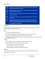
Caution
Risk of explosion if battery is replaced by an incorrect type. Dispose of used batteries
according to the instructions.
! Warning - To prevent the risk of fire or shock hazards, and do not
expose the product to moisture.
! Warning - Please do not open or disassemble the product as this
may cause electric shock.
! Warning - Power cord shall be connected to a socket-outlet with
earth connection.
! Warning - The cable cover cannot be removed under normal use
conditions.
! Warning -
Stability Hazard. The touch monitor may fall, causing
serious personal injury or death. To prevent injury, this touch
monitor must be securely attached to the wall in accordance with
the installation instructions.

5 |
Avis d’utilisation
Précautions
Veuillez suivre toutes les mises en garde, précautions et entretiens recommandés dans ce
manuel d’utilisation pour maximiser la durée de vie de votre unité.
À faire :
▪ Éteindre l’appareil avant de le nettoyer.
▪ Utiliser un chiffon humidifié par une solution savonneuse pour nettoyer le boîtier du produit.
▪ Utiliser uniquement l’adaptateur d’alimentation prescrit pour votre appareil.
▪ Débrancher l’appareil lorsqu’il n’est pas utilisé pendant une période prolongée.
À éviter :
▪ Ne pas utiliser de nettoyants abrasifs, de cires ou de solvants pour le nettoyage
▪ Ne jamais utiliser l’appareil dans les conditions suivantes :
– des conditions environnementales extrêmes (chaud, froid ou humidité)
– des endroits remplis de poussières et de saletés.
– à proximité d’appareils produisant un fort champ magnétique.
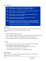
Mise en garde
Risque d'explosion si la batterie est remplacée par un type incorrect. Jetez les piles
usagées conformément aux instructions.
! Mise en garde — Pour prévenir les risques d’incendie ou
d’électrocution, ne pas exposer le produit à l’humidité.
! Mise en garde — Prière de ne pas ouvrir ou démonter le produit, car
cela pourrait entraîner l’électrocution.
! Mise en garde – Le cordon d’alimentation doit être branché à une
prise pourvue d’une mise à la terre.
! Mise en garde – La gaine du câble ne doit pas être retirée en
conditions normales d’utilisation.
! Mise en garde — Risque de renversement. Le moniteur tactile peut se
renverser et causer de graves blessures corporelles, voire la mort.
Pour prévenir les blessures, ce moniteur tactile doit être solidement
fixé au mur selon les instructions d’installation.

6 |
Table of Contents
Chapter 1 ........................................................................................................................ 7
1.1 Overview .................................................................................................................... 8
1.2 Feature ....................................................................................................................... 8
1.3 Specifications ............................................................................................................. 8
1.4 Block Diagram.......................................................................................................... 10
1.5 Interface Connectors ................................................................................................ 11
1.6 Package Overview ................................................................................................... 14
Chapter 2 ...................................................................................................................... 15
2.1 About VESA Mount .................................................................................................. 16
2.2 Power On / Off Switch .............................................................................................. 17
2.3 Dimension ................................................................................................................ 18
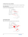
2.4 Optional Accessory Installation ................................................................................ 21
2.4.1 Install the Stand ............................................................................................... 21
2.4.2 Remove the Stand ........................................................................................... 21
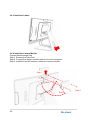
2.4.3 Install the Cables .............................................................................................. 22
2.4.4 Install the Camera Module ............................................................................... 22
2.4.5 Remove the Camera ........................................................................................ 23
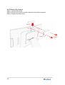
2.4.6 Install the MSR Module .................................................................................... 24
2.4.7 Remove the MSR Module ................................................................................ 25
Appendix ...................................................................................................................... 27
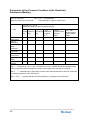
Declaration of the Presence Condition of the Restricted Substances Marking .............. 28

7 |
Chapter 1
Product Introduction

8 |
1.1 Overview
The IC-156P-AW3 is a thin 15.6” touch computer that offers a unique design with
expandability and flexibility, making expansion and accessory installation easy. The
versatility of IC-156P-AW3 is an exceptional choice for applications in all business sectors,
especially in the retail market.
1.2 Feature
▪ Intel I3-7100U processor.
▪ Sleek design for a better user experience.
▪ Patented I/O design for better wiring management while implementation.
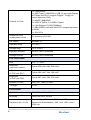
1.3 Specifications
System
CPU Intel I3-7100U Processor, 3MB Cache, up to 2.4 GHz
GPU Intel HD Graphics 620
DDR 2 x SO-DIMM, DDR4, Support up to 32GB/64bits,
2133MT/s
Storage 1 x M.2 2280 (SATA III & NVME)
Input Power DC in 24V/5A 4PIN
Display Dual channel LVDS, resolution up to 1920x1080P60
Touch
ZCC (EETI 80W60 controller) /TPK (EETI 80H84
controller) 15.6-inch P-Cap touch sensor, supports 10
fingers touch function.
Audio 2 x speaker (2W x 2)
Network
Gigabit Ethernet (Intel i219LM)
Optional m.2 2230 module: Intel AC 3168, Wi-Fi
802.11a/b/g/n/ac 1T1R, Bluetooth 4.2 (Support BLE)

9 |
External IO Ports
1 x Power button
1 x USB Type-C (USB3CM:1x USB 3.1 gen1 with Display
ALT Mode and PD2.0, support 5V@3A / 12V@2.5A
output, Maximum 30W.)
1 x MiniDP (4K@60HZ)
2 x USB2.0 Type-A, 2 x USB3.0 Type-A
1 x LAN (Support 10/100/1000Mbps)
1 x DB9 (RS232, pin9 with NA/5V/12V support that select
by BIOS)
1 x 24V DC In
Internal IO Ports
(inside plastic cover) 3 x connector (5V/0.5A)
OS version Windows 10
Operation temp. 0°C~40°C
Storage temp. -20°C to 60°C
Operation humidity 20~80%, Non-Condensing
Storage humidity 10~90%, Non-Condensing
LCD Touch Panel
Size 15.6” TFT LCD
Brightness
(non-touch screen) Typical 450 cd/m2; Min. 360 cd/m2
Brightness
(P-CAP with ZCC) Typical 382 cd/m2; Min. 306 cd/m2
Brightness
(P-CAP with TPK) Typical 387 cd/m2; Min. 313 cd/m2
Number of Pixels 1920 (H) × 1080 (V)/ 60Hz
Tilt Angle 8°~68°
Environment
Certificate CE、FCC、LVD、UKCA
Mounting VESA 100 mm x 100 mm
Dimension (W x H x D)
System Only:369.1 mm x 223.7 mm x 35.2 mm
System with Stand Module:369.1 mm x 291.6 mm x
169.4 mm

10 |
Net Weight System Only:2.01 Kg
System with Stand Module:4.01 Kg
Gross Weight System Only:3.01 Kg
System with Stand Module:6.01 Kg
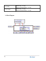
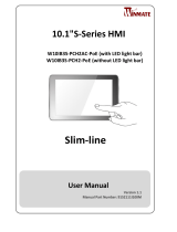
1.4 Block Diagram

11 |
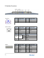
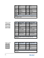
1.5 Interface Connectors
24V DC In Pin # Signal Name Pin # Signal Name
1 GND 2 GND
3 24V 4 24V
RJ45 for LAN
Pin # Signal Name Pin # Signal Name
1 TP1+ 2 TP1-
3 TP2+ 4 TP3-
5 TP3+ 6 TP2-
7 TP4+ 8 TP4-
LED Function Color
LED1 Speed
1000 Orange
100 Green
10 Non
LED2 Active Yellow
USB-C Pin # Signal Name Pin # Signal Name
A1 GND B12 GND
A2 SSTXp1 B11 SSRXp1
A3 SSTXn1 B10 SSRXn1
A4 VBUS B9 VBUS
A5 CC1 B8 SBU2

12 |
A6
Dp1
B7
Dn2
A7
Dn1
B6
Dp2
A8 SBU1 B5 CC2
A9 VBUS B4 VBUS
A10 SSRXn2 B3 SSTXn2
A11 SSRXp2 B2 SSTXp2
A12 GND B1 GND
Note
USB3CM: Support DP ALT mode and 5V@3A /
12V@3A output;
USB 3.0 Dual Pin # Signal Name Pin # Signal Name
1
USB5V
10
USB5V
2 D- 11 D-
3 D+ 12 D+
4 GND 13 GND
5 StdA_SSRX- 14 StdA_SSRX-
6 StdA_SSRX+ 15 StdA_SSRX+
7 GND_DRAIN 16 GND_DRAIN
8 StdA_SSTX- 17 StdA_SSTX-
9 StdA_SSTX+ 18 StdA_SSTX+
Note
Every on USB3.0 Power current provide 0.9A
(Regular)
USB 2.0 Dual Pin # Signal Name Pin # Signal Name
1 USB5V 1 USB5V
2 D- 2 D-
3 D+ 3 D+
4 GND 4 GND
Note
Every on USB2.0 Power current provide 0.5A
(Regular)

13 |
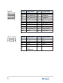
Mini DP Pin # Signal Name Pin # Signal Name
1 GND 2 Hot Plug Detect
3 ML_Lane 0 (p) 4 CONFIG1
5 ML_Lane 0 (n) 6 CONFIG2
7 GND 8 GND
9
ML_Lane 1 (p)
10
ML_Lane 3 (p)
11 ML_Lane 1 (n) 12 ML_Lane 3 (n)
13 GND 14 GND
15 ML_Lane 2 (p) 16 AUX_CH (p)
17 ML_Lane 2 (n) 18 AUX_CH (n)
19 GND 20 DP_PWR
DB9 for RS232 Pin # Signal Name Pin # Signal Name
1 DCD 2 SIN
3
SOUT
4
DTR
5 GND 6 DSR
7 RTS 8 CTS
9
0V / 5V/ 12V
Max.
current=1A

14 |
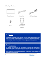
1.6 Package Overview
Touch Computer Power Cord DC Power Supply
Screw Stand Module
(Optional)
! Warning!
This product is intended to be supplied by a UL Listed Power Adapter, rated
24Vdc, 5A minimum. (complied with LPS or PS2) Tma = 40 degree C minimum,
and the altitude of operation = 3048m minimum. If it needs further assistance with
purchasing the power source, please contact to TES for further information.
! Mise en garde!
Cet appareil est conçu avec une alimentation de courant CA, d’une tension
nominale de 24Vdc, 5A minimum. (conforme au LPS ou PS2) Tma = 40 degrés C
minimum et l’altitude de l’utilisation = 3048m minimum. Pour d’autres conseils
pour l’installation de la source d’alimentation, communiquer avec TES pour de
plus amples renseignements.

15 |
Chapter 2
Product Installation

16 |
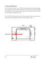
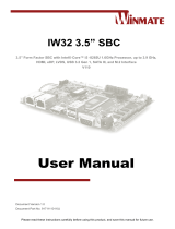
2.1 About VESA Mount
The IC-156P-AW3 conform to the “VESA Flat Display Mounting Interface Standard”
which defines a physical mounting interface for touch computer, and corresponding with
the standards of touch computer mounting devices, such as wall-mounted. The VESA
mount is located on the back of this unit.
The IC-156P-AW2 may be wall mounted in the horizontal position (output connector
facing down) or vertical position (output connector facing left or right).
VESA Mount

17 |
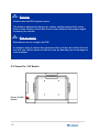
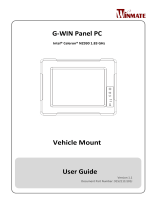
2.2 Power On / Off Switch
Power On/Off
Switch
! Warning!
Please select the TES original screws!
The distance between the back cover surface and the bottom of the screw
hole is 8 mm. Please use four M4 / 8 mm screws diameter with proper length
to mount your monitor.
! Mise en garde!
Sélectionner les vis d’origine de TES!
La distance entre la surface du couvercle arrière et le bas de l’orifice de la vis
est de 8 mm. Utiliser quatre vis M4 de 8 mm de diamètre pour le montage de
votre moniteur.

18 |
Function Description
Power on Press the power button.
Sleep With OS settings, sleep or shut down choose one.
Power off
Force
power off
Press the power button 4 sec.
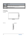
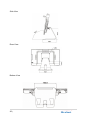
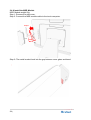
2.3 Dimension
2.3.1 System Only
Front View
Side View

19 |
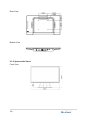
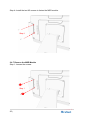
Rear View
Bottom View
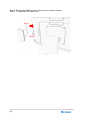
2.3.2 System with Stand
Front View
La page est en cours de chargement...
La page est en cours de chargement...
La page est en cours de chargement...
La page est en cours de chargement...
La page est en cours de chargement...
La page est en cours de chargement...
La page est en cours de chargement...
La page est en cours de chargement...
La page est en cours de chargement...
-
 1
1
-
 2
2
-
 3
3
-
 4
4
-
 5
5
-
 6
6
-
 7
7
-
 8
8
-
 9
9
-
 10
10
-
 11
11
-
 12
12
-
 13
13
-
 14
14
-
 15
15
-
 16
16
-
 17
17
-
 18
18
-
 19
19
-
 20
20
-
 21
21
-
 22
22
-
 23
23
-
 24
24
-
 25
25
-
 26
26
-
 27
27
-
 28
28
-
 29
29


MicroTouch IC-156P-AW3 All -In-One Touch Computer Mode d'emploi
- Taper
- Mode d'emploi
dans d''autres langues
Documents connexes
-
 MicroTouch IC-215P-AW3 Touch Computer Mode d'emploi
-
 MicroTouch IC-156P-AW4-W10 Manuel utilisateur
-
 MicroTouch IC-156P-AW1-W10 Touch Computer Manuel utilisateur
-
 MicroTouch IC-215P-AW1-W10 Touch Computer Manuel utilisateur
-
 MicroTouch SK-097P-A2 Slimline Kiosk Touch Monitor Manuel utilisateur
-
 MicroTouch MP-000-AA2 Android Media Player Manuel utilisateur


Autres documents
-
Trust ZCC-3500 Manuel utilisateur
-
 Winmate R15IB7T-POC3 Guide de démarrage rapide
-
 Winmate R17IK7T-POM1 Guide de démarrage rapide
-
 Winmate W15IB3S-POA4 Guide de démarrage rapide
-
 Winmate W10IB3S-PCH2AC-PoE S-Series Manuel utilisateur
-
 Winmate W12IB3S-VMM9 Guide de démarrage rapide
-
 Winmate IW32 3.5 SBC Manuel utilisateur
-
 Winmate G-WIN Manuel utilisateur
-
 Winmate W10IB3S-PCH2AC-PoE S-Series Guide de démarrage rapide
-
 Winmate W22IK7T-GCA3 Guide de démarrage rapide


