Velleman VTTEST11N Manuel utilisateur
- Catégorie
- Stroboscopes
- Taper
- Manuel utilisateur

VTTEST
1
CABLE TRAC
K
KABELTESTE
R
TESTEUR DE
C
DETECTOR D
E
KABELFINDE
R
USER MANUAL
GEBRUIKERSH
MODE D'EMPL
O
MANUAL DEL
U
BEDIENUNGS
A
1
1N
K
ER WITH TONE GE
N
R
MET TOONGENER
A
C
ÂBLE AVEC G
É
N
ÉR
E
CABLES CON GEN
E
R
MIT TONGENERA
T
ANDLEIDING
O
I
U
SUARIO
A
NLEITUNG
N
ERATOR
A
TOR
R
ATEUR DE TONALI
T
E
RADOR DE TONOS
T
OR
3
8
14
20
26
TÉ

VTTEST11N
V. 01 – 15/01/2013 2 ©Velleman nv

V. 01 – 15/01
/
1. Introduc
t
To all reside
n
Important e
n
This
disp
o
envi
r
unso
spec
i
returned to yo
u
the local envir
o
If in doubt, c
o
Thank you for
before brin
g
in
g
transit, don't i
n
This cable trac
without dama
g
checkin
g
for o
p
2. Safety I
n
Refer to the V
e
pa
g
es of this
m
War
n
shoc
k
hand
s
circui
t
the
m
In thi
s
elect
r
Do n
o
Not f
o
or pe
r
• Keep this d
e
temperatur
e
• Protect this
operatin
g
t
h
VTTES
T
/
2013 3
USER M
A
t
ion
n
ts of the European
n
vironmental infor
m
symbol on the device
o
sal of the device afte
r
onment. Do not disp
o
rted municipal waste
;
i
alized company for r
e
u
r distributor or to a l
o
nmental rules.
o
ntact your local w
a
choosin
g
Velleman! P
g
this device into ser
v
n
stall or use it and co
n
ker is desi
g
ned to ide
g
in
g
the insulation, an
p
ens / shorts.
n
structions
e
lleman® Service a
n
m
anual.
n
in
g
: Live, facility ele
c
k
s, burns, and even d
e
s
or arms. If the cabl
e
t
, the circuit breaker
o
m
ain breaker box befo
r
s
case, the cable trac
k
r
ician.
o
t use the device in a
o
llowin
g
instructions
m
r
sonal in
j
ury.
e
vice away from rain
a
e
s.
device from shocks a
h
e device.
T
11N
©
A
NUAL
Union
m
ation about this pr
o
or the packa
g
e indic
a
r its lifecycle could h
a
o
se of the unit (or bat
;
it should be taken t
o
e
cyclin
g
. This device
s
ocal recyclin
g
service
a
ste disposal auth
o
lease read the manu
a
v
ice. If the device was
n
tact your dealer.
ntify and trace wires
a
d to test continuity al
n
d
Q
uality Warrant
y
c
trical circuits can ca
u
e
ath if the circuit is to
e
tracker is used for t
h
o
r fuse must be remo
v
r
e trackin
g
any electr
i
k
in
g
should be done
b
hi
g
h volta
g
e environ
m
m
ay cause dama
g
e to
a
nd moisture, dust a
n
nd abuse. Avoid brut
e
©
Velleman nv
o
duct
a
tes that
a
rm the
teries) as
o
a
s
hould be
. Respect
o
rities.
a
l thorou
g
hly
dama
g
ed in
a
nd cables
lowin
g
y
on the last
u
se serious
uched by
h
is type of
v
ed from
i
cal circuit.
b
y a licensed
m
ent.
the device
n
d extreme
e
force when

V. 01 – 15/01
/
• Always swit
c
• Familiarise
y
using it.
• All modifica
t
Dama
g
e ca
u
by the warr
a
• Only use th
e
an unautho
r
• Dama
g
e ca
u
is not cover
e
responsibili
t
• Keep this m
3. Overvie
w
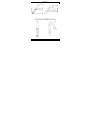
Refer to the ill
u
cable tracker
1 probe ti
p
2 volume
c
3 trace bu
t
4 speaker
5 3.5 mm
4. Operatio
n
Neve
r
powe
r
4.1 Cable
T
The tone
g
ene
r
is interrupted
(
1. Set the to
2. Create a
s
end of th
e
3. Connect t
h
tested:
o If the
C
uninter
VTTES
T
/
2013 4
c
h off both the trans
m
y
ourself with the func
t
ions of the device ar
e
u
sed by user modifica
a
nty.
e
device for its intend
r
ised way will void th
e
u
sed by disre
g
ard of
c
e
d by the warranty a
n
t
y for any ensuin
g
de
f
anual for futu
r
e refer
e
w
u
strations on pa
g
e 2
o
(receiver)
p
c
ontrol
t
ton
headphones output
n
r
connect the test lea
d
r
ed line.
T
est
r
ator can be used to
d
(
test per wire pair).
ne
g
enerator’s mode
s
s
hort circuit between
t
e
cable.
h
e red and black con
n
C
ONT indicator [8] li
g
rupted.
T
11N
©
m
itter and the receive
tions of the device b
e
e
forbidden for safety
tions to the device is
ed purpose. Usin
g
th
e
e
warranty.
c
ertain
g
uidelines in t
h
n
d the dealer will not
f
ects or problems.
e
nce.
o
f this manual.
tone
g
enerator (s
e
6 test leads
7 phone connec
t
8 LED indicators
9 mode switch
d
s with an active AC
o
d
etermine whether or
s
witch [9] to CONT.
t
he wires to be tested
n
ectors [6] to the wir
e
hts up, the two teste
d
©
Velleman nv
r after use.
e
fore actually
reasons.
not covered
e
device in
h
is manual
accept
e
nder)
t
or
o
r DC-
not a cable
at the far
e
s to be
d
wires are

VTTEST11N
V. 01 – 15/01/2013 5 ©Velleman nv
o If the CONT indicator [8] does not light, one or both of the
wires are broken, or the wrong wires were connected or short
circuited.
Caution: Make sure the pair of wires under test is not in contact
with any other electrified or earthed object, as this may cause an
incorrect result.
4.2 Cable Detection / Test
Use both the tone generator and the cable tracker to verify where a
cable is going, if it is interrupted or not and where the interruption is
located.
1. Set the tone generator's mode switch [9] to TONE.
The TONE indicator [8] starts flashing.
2. At one end of the cable / wires to be tested, connect the red clip
to any wire or one specific wire you want to test. Connect the
black clip to the ground wire or, if you cannot find it, one of the
other wires.
3. Use the volume control [2] on the side of the cable tracker to
control the volume.
4. Use the probe tip [1] of the cable tracker as follows:
o If you do not know where the cable is going or if there are
several similar cables, you can detect the correct one with the
probe. Hold the probe to the suspected wire and press the
trace button. The signal is the loudest at the correct wire.
o If you do know where the cable is going, the probe allows you
to verify immediately at the other end whether or not the
cable is interrupted. Hold the probe to the end of the wire and
press the trace button. If no signal is obtained, the test wire
is probably interrupted.
o Press and hold the trace button [3] and follow the cable to
where the signal stops: the signal wire is interrupted at that
point.
Remarks:
• The best test results are obtained when the black clip is connected
to a separate ground wire.
• The probe is very sensitive: as it gets nearer the signal wire, the
tone gets louder.
• Electric fields may interfere with the detection of the signal wire.

VTTEST11N
V. 01 – 15/01/2013 6 ©Velleman nv
4.3 RJ12 Phone Connector Test
The tone generator can be used to determine the polarity of a phone
line, and the status of a working line.
1. Set the tone generator's mode switch [9] to OFF.
2. Insert the phone line connector [7] in the phone socket and
connect the red and black connectors [6] to the wires to be
connected. The CONT indicator [8] lights.
o Green means the polarity is correct (black is "+" (tip) and red
is "–" (ring)).
o Red means the polarity is inversed (black is "–" (ring) and red
is "+" (tip)).
o If the LED does not light up, either the connections are not
established correctly or the socket is not connected.
3. To test the status of a telephone line, first connect the red
connector to the "–" (ring) side and the black connector to the
"+" (tip) side. The CONT indicator [8] lights.
o Green indicates a clear line.
o Flickering yellow means there is an incoming phone call (ring
signal).
Note: In this case, set the mode switch to CONT to terminate
the call on the line.
o If the LED does not light up, the line is busy.
4.4 Selecting the Tone
Select the tone you want to hear (single or dual tone) with the audio
signal switch at the inside of the tone generator.
1. Open the battery compartment and remove the battery.
2. Unscrew the screw in the battery compartment and the four
screws in the back cover.
3. Carefully remove the back cover and lift the PCB.
The audio signal switch is located at the left side of the PCB
(component side up, battery connectors at the bottom).
4. Set the switch in the desired position.
5. Replace the PCB carefully and put the cover back.
Caution: Make sure that no wires are crimped and that the
mode switch is in position. The indicator LEDs should fit easily
through the holes. Do not force.
6. Fix the back cover with the 5 screws.
7. Replace the battery and close the cover.

V. 01 – 15/01
/
5. Batteries
Do n
o
explo
d
batte
r
local
r
1. On the to
n
2. Slide ope
n
(9 V, 6LF
2
3. Close the
4. On the ca
b
5. Replace t
h
6. Close the
6. Storage
• Remove th
e
lon
g
time.
O
• Store the d
e
temperatur
e
7. Technica
l
tone
g
enerato
r
workin
g
v
o
output wa
v
sin
g
le audi
dual audio
cable tracker
workin
g
v
o
max. rece
p
maximum
dimensions
receiver
transmit
t
total weight
VTTES
T
/
2013 7
o
t puncture batteries
o
d
e. Do not attempt to
r
ies (alkaline). Dispos
e
r
e
g
ulations. Keep bat
t
n
e
g
enerator, set the
n
the battery cover at
2
2). Respect the pola
r
battery cover.
b
le tracker, unscrew
t
h
e battery (9 V, 6LF2
2
battery cover and ti
gh
e
batteries from the d
e
O
ld batteries can be
g
i
n
e
vice in a dry and du
s
e
.
l
Specifications
r
o
lta
g
e DC
9
v
e form squa
o frequency ± 1
5
frequency ± 1
3
o
lta
g
e DC
9
p
tion sensitivity > 3
0
output volume ± 1
0
238 x 43 ×
2
t
e
r
145 × 35 ×
2
± 1
6
T
11N
©
o
r throw them in fire
a
rechar
g
e non-rechar
g
e
of batteries in acco
r
t
eries away from chil
d
mode switch [9] to
O
the back and replace
r
ity.
t
he battery cover at t
h
2
). Respect the polari
t
h
ten the screw.
e
vice if it will not be
u
n
to leak and dama
g
e
s
t-free place at room
9
V (battery not incl.)
re wave si
g
nals ± 3.
5
5
00 Hz
3
00 Hz - 1700 Hz
9
V (battery not incl.)
0
mV
0
0 dB
2
6 mm / 9.4" × 1.7"
×
2
5 mm / 5.7" × 1.4"
×
6
0
g
©
Velleman nv
a
s they may
g
eable
r
dance with
d
ren.
O
FF.
the battery
h
e back.
t
y.
u
sed for a
the device.
5
Vpp
×
1.0"
×
1.0"

V. 01 – 15/01
/
Use this devi
c
cannot be he
l
resulting fro
m
For more inf
o
of this manu
a
The informat
i
prior notice.
© COPYRIGH
T
The copyri
g
h
t
worldwide ri
g
reproduced, tr
a
otherwise with
G
E
1. Inleiding
Aan alle in
g
e
z
Belan
g
ri
j
ke
m
Dit s
y
als h
scha
d
even
afval
terechtkomen
v
naar een loka
a
milieuwet
g
evi
n
Hebt u vra
g
e
n
betreffend d
e
Dank u voor u
w
toestel in
g
ebr
transport, inst
a
Deze kabeltes
t
identificeren z
o
VTTES
T
/
2013 8
c
e with ori
g
inal acc
l
d responsible in th
e
m
(incorrect) use o
f
o
concernin
g
this pr
a
l, please visit our
w
i
on in this manual i
s
T
NOTICE
t
to this manual is
o
g
hts reserved. No p
a
a
nslated or reduced t
o
out the prior written
c
E
BRUIKERSH
z
etenen van de Eur
o
m
ilieu-informatie b
e
y
mbool op het toeste
l
et na zi
j
n levenscyclu
d
e kan toebren
g
en a
a
tuele batteri
j
en) niet
; het moet bi
j
een
g
e
s
v
oor recycla
g
e. U mo
e
a
l recycla
g
epunt bren
g
ng
.
n
, contacteer dan d
e
verwi
j
derin
g
.
w
aankoop! Lees dez
e
uik neemt. Werd het
t
a
lleer het dan niet en
t
er werd ontworpen o
m
o
nder beschadi
g
in
g
v
a
T
11N
©
essories only. Vell
e
e
event of dama
g
e
o
f
this device.
oduct and the late
s
w
ebsite www.velle
m
s
sub
j
ect to chan
ge
o
wned by Velleman
a
rt of this manual ma
y
o
any electronic medi
c
onsent of the copyri
g
ANDLEIDIN
G
o
pese Unie
e
treffende dit produ
l
of de verpakkin
g
g
e
e
s wordt we
gg
eworpe
n
a
n het milieu. Gooi dit
bi
j
het
g
ewone huish
o
s
pecialiseerd bedri
j
f
e
t dit toestel naar uw
g
en. Respecteer de pl
a
e plaatseli
j
ke auto
r
e
handleidin
g
g
rondi
g
t
oestel beschadi
g
d ti
jd
raadplee
g
uw dealer.
m
een kabel op te sp
o
a
n de isolatie, en de c
©
Velleman nv
e
man nv
o
r in
j
ury
s
t version
m
an.eu.
e
without
nv. All
y
be copied,
um or
g
ht holder.
G
ct
e
ft aan dat,
n
, dit toestel
toestel (en
o
udeli
j
ke
verdeler of
a
atseli
j
ke
r
iteiten
voor u het
d
ens het
o
ren en te
ontinuïteit

V. 01 – 15/01
/
te testen om t
e
ontstaan.
2. Veili
g
hei
d
Raadpleeg de
V
achteraan dez
e
Waa
r
onde
r
bran
d
kabel
t
stroo
m
zeker
teste
n
door
e
Gebr
u
span
n
Het n
verw
o
• Bescherm d
temperatur
e
• Bescherm t
e
bediening.
• Schakel na
g
• Leer eerst
d
gebruiken.
• Om veili
g
h
e
Schade doo
niet onder
d
• Gebruik het
onoordeelk
u
• De
g
arantie
richtli
j
nen i
n
verantwoor
d
rechtstreek
s
• Bewaar dez
e
VTTES
T
/
2013 9
e
zien of de leidin
g
d
o
d
sinstructies
V
elleman® service-
e
handleidin
g
.
r
schuwin
g
: Het aanr
a
r
stroom in
g
ebouwen
d
wonden en zelfs fatal
t
ester
g
ebruikt wordt
m
onderbreker of zek
e
in
g
kast alvorens een
d
n
. In dit
g
eval, dient
d
e
en erkende elektrici
e
u
ik het toestel niet in
n
in
g
.
iet naleven van instr
u
o
ndin
g
en veroorzaken
it toestel te
g
en re
g
en
e
n.
eg
en schokken. Verm
i
g
ebruik zowel de zen
d
d
e functies van het to
e
e
idsredenen ma
g
u
g
e
e
r wi
j
zi
g
in
g
en die de
ge
d
e
g
arantie.
toestel enkel waarvo
u
ndi
g
g
ebruik vervalt
g
eldt niet voor scha
d
n
deze handleidin
g
en
d
eli
j
kheid afwi
j
zen vo
o
s
verband mee houde
e
handleidin
g
voor ve
T
11N
©
o
orloopt en
g
een kort
s
en kwaliteits
g
ara
n
a
ken van elektrische
c
kan leiden tot ernsti
g
e
g
evol
g
en hebben. I
voor dit type circuits
,
e
rin
g
verwi
j
derd word
e
d
er welk elektrisch cir
c
d
e kabeltest te worde
n
e
n.
een om
g
evin
g
onder
h
u
cties kan materiële s
c
.
en vochti
g
heid, stof
ij
d brute kracht ti
j
de
n
d
er als de ontvan
g
er
u
e
stel kennen voor u h
e
e
n wi
j
zi
g
in
g
en aanbr
e
e
bruiker heeft aan
g
e
b
or het
g
emaakt is. Bi
j
de
g
arantie.
d
e door het ne
g
eren v
a
uw dealer zal de
o
r defecten of proble
m
n.
rdere raadple
g
in
g
.
©
Velleman nv
s
luitin
g
is
n
tie
c
ircuits
g
e schokken,
ndien de
,
moet de
e
n uit de
c
uit te
n
uit
g
evoerd
h
o
g
e
c
hade of
en extreme
n
s de
u
it.
e
t
g
aat
e
n
g
en.
b
racht valt
j
a
n bepaalde
m
en die hier

V. 01 – 15/01
/
3. Omschri
jv
Raadplee
g
de
a
meetsonde (
o
1 testpunt
2 volumer
e
3 zoekkno
4 luidspre
k
5 3.5 mm
-
4. Gebruik
Verbi
n
of li
j
n
4.1 Kabelt
e
Met de toon
g
e
n
onderbroken i
s
1. Zet de m
o
2. Maak aan
de kabelk
e
3. Verbind d
e
kabelkern
e
o Als si
gn
onderb
r
o Als si
gn
kernen
aan
g
es
l
Let op: zor
g
e
contact maken
stroom; dit ka
n
4.2 Kabeld
Gebruik zowel
komen waar e
e
zo
j
a: waar di
e
1. Zet de m
o
De si
g
naa
l
VTTES
T
/
2013 1
0
v
in
g
a
fbeeldin
g
en op pa
g
i
n
o
ntvan
g
er)
eg
elin
g
p
k
er
-
koptelefoonuitgang
n
d de meetsnoeren n
o
en (AC of DC).
e
st
n
erator kunt u bepal
e
s
(test per twee kabel
o
dusschakelaar van d
e
het andere eind van
d
e
rnen die u wil testen
e
rode en zwarte kle
m
e
n:
n
aalled CONT [8] opli
c
r
oken.
n
aalled CONT [8] nie
t
onderbroken, ofwel z
l
oten of kort
g
esloten.
rvoor dat de kabelke
r
met een
g
eaard voo
r
n
een on
j
uist testresu
etectie / -test
de toon
g
enerator als
e
n kabel naartoe
g
aa
t
e
onderbrekin
g
zich b
e
o
dusschakelaar van d
e
l
led TONE [8] be
g
int
T
11N
0
©
n
a 2 van deze handlei
d
toon
g
enerator (z
e
6 testdraden
7 telefoonconne
c
8 signaalleds
9 modusschakel
a
o
oit met stroomvoere
e
n of een kabel al dan
kernen).
e
toon
g
enerator [9]
o
d
e kabel een kortsluit
.
m
men [6] met de te t
e
c
ht, zi
j
n de twee ker
n
t
oplicht, is ofwel één
i
j
n de verkeerde kern
r
nen die
g
etest worde
r
werp of een voorwer
p
ltaat opleveren.
de meetsonde om te
t
, of een kabel onder
b
e
vindt.
e
toon
g
enerator [9]
o
te knipperen.
©
Velleman nv
d
in
g
.
e
nder)
c
tor
a
ar
nde kabels
niet
o
p CONT.
in
g
tussen
e
sten
n
en niet
of beide
en
n
g
een
p
onder
weten te
b
roken is en
o
p TONE.

VTTEST11N
V. 01 – 15/01/2013 11 ©Velleman nv
2. Verbind aan het ene uiteinde van de te testen kabel de rode
klem met eender welke draadkern, of één specifieke kern die u
wil testen. Zet de zwarte klem op de aarding of, als deze niet
voorhanden is, op een van de andere draadkernen.
3. De geluidssterkte is regelbaar met de volumeregeling [2].
4. Gebruik het testpunt [1] als volgt:
o Als u niet weet waar een kabel naartoe gaat of er zijn
verschillende gelijke kabels, kunt u de juiste kabel vinden met
de sonde. Houd de sonde tegen de vermoedelijke kabel en
druk op de zoekknop. Het signaal klinkt het luidst ter hoogte
van de juiste kabel.
o Als u wel weet waar een kabel uitkomt, kunt u aan het andere
eind meteen testen of de kabel niet onderbroken is. Houd de
sonde tegen het uiteinde van de kabel en druk op de
zoekknop. Als er geen signaal is, is de geteste draadkern
waarschijnlijk ergens onderbroken.
o Volg de kabel terwijl u de zoekknop [3] ingedrukt houdt tot
waar het signaal ophoudt; de draadkern is op dat punt
onderbroken.
Opmerkingen:
• U zult de beste testresultaten krijgen wanneer de zwarte klem
met een afzonderlijke aardekabel is verbonden.
• De sonde is zeer gevoelig: naarmate ze dichter bij de kabel komt,
wordt de toon luider.
• Elektrische velden kunnen de ontvangst van de signaalkabel
storen.
4.3 Telefoonaansluitingtest (RJ12)
De toongenerator kan worden gebruikt om de polariteit van een
telefoonlijn te bepalen, en de status van een actieve lijn.
1. Zet de modusschakelaar van de toongenerator [9] op OFF.
2. Steek de telefoonconnector [7] in de contactdoos van de
telefoon en verbind de rode en zwarte klemmen [6] met de
draden die moeten aangesloten worden. De signaalled CONT [8]
licht op.
o Groen betekent dat de polariteit juist is (zwart is "+" (tip) en
rood is "–" (ring)).
o Rood betekent dat de polariteit omgekeerd is (zwart is "–"
(ring) en rood is "+" (tip)).

V. 01 – 15/01
/
o Als de l
de con
t
3. Om de st
a
klem aan
o
(tip) kant.
o Een
g
r
o
o Een kni
oproep
Opme
r
om de
o
o Indien
d
4.4 De too
n
Selecteer de t
o
de audiosi
g
na
a
1. Open het
b
2. Draai de s
de achter
k
3. Verwi
j
der
De audios
i
(met com
p
onderaan
)
4. Zet de sc
h
5. Plaats de
p
Let op: Z
o
modussch
moeten
ge
6. Bevesti
g
d
7. Plaats de
b
5. Batteri
j
e
n
U ma
g
(expl
o
batte
r
Houd
1. Op de too
n
2. Schuif het
en vervan
g
3. Sluit het
b
VTTES
T
/
2013 1
2
ed niet oplicht zi
j
n d
e
t
actdoos niet aan
g
esl
o
a
tus te testen van ee
n
o
p de "–" (rin
g
) kant
De si
g
naalled CONT
o
en led betekent een
v
pperende
g
ele led be
t
is (belsi
g
naal).
r
kin
g
: In dit
g
eval, z
e
o
proep op de li
j
n te b
e
d
e led niet oplicht, da
n
selecteren
o
on die u wenst te ho
r
a
lschakelaar in de too
n
b
atteri
j
vak en verwi
jd
chroef los van het ba
t
k
lep.
voorzichti
g
de achter
k
ig
naalschakelaar bevi
p
onentenzi
j
de naar b
o
)
.
h
akelaar in de
g
ewen
s
p
rintplaat en de klep
v
o
r
g
ervoor dat er
g
ee
n
akelaar op de
j
uiste
p
e
makkeli
j
k doorheen
d
d
e achterklep met de
5
b
atteri
j
teru
g
en sluit
n
g
batteri
j
en nooit doo
o
sie
g
evaar). Herlaad
g
r
i
j
en we
g
vol
g
ens de
p
batteri
j
en uit het ber
e
ng
enerator, zet de m
o
batteri
j
deksel open
a
g
de batteri
j
(9 V, 6L
F
b
atteri
j
deksel.
T
11N
2
©
e
aansluitin
g
en niet c
o
o
ten.
n
telefoonli
j
n, sluit ee
r
en de zwarte klem o
p
[8] licht op.
v
ri
j
e li
j
n.
t
ekent dat er een bin
n
e
t de modusschakelaa
e
ëindi
g
en.
n is de li
j
n bezet.
r
en (enkele of dubbel
e
ng
enerator.
d
er de batteri
j
.
t
teri
j
vak en de 4 schr
k
lep en de printplaat.
ndt zich links van de
p
o
ven, de batteri
j
klem
m
s
te positie.
v
oorzichti
g
teru
g
.
n
kabels
g
ekneld zitt
e
p
laats staat. De si
g
na
a
d
e
g
aat
j
es passen. Ni
e
5
schroeven.
het batteri
j
vak.
rboren of in het vuur
g
een alkalinebatteri
j
e
n
p
laatseli
j
ke milieuwet
g
e
ik van kinderen.
o
dusschakelaar [9] o
p
a
an de achterkant va
n
F
22). Respecteer de
p
©
Velleman nv
o
rrect of is
r
st de rode
p
de "+"
n
enkomende
r op CONT
e
toon) met
oeven van
p
rintplaat
m
en
e
n en dat de
a
lleds
e
ts forceren.
g
ooien
n
. Gooi
g
evin
g
.
p
OFF.
n
het toestel
p
olariteit.

VTTEST11N
V. 01 – 15/01/2013 13 ©Velleman nv
4. Op de kabeltester, schroef het batterijdeksel aan de achterkant
van het toestel los.
5. Vervang de batterij (9 V, 6LF22). Respecteer de polariteit.
6. Sluit het batterijvak en draai de schroef vast.
6. Opbergen
• Verwijder de batterijen als het toestel gedurende een langere tijd
niet gebruik wordt. Oude batterijen kunnen lekken en het toestel
beschadigen.
• Bewaar het toestel in een droge en stofvrije ruimte op
kamertemperatuur.
7. Technische specificaties
toongenerator
werkspanning DC 9 V (batterij niet meegelev.)
uitgangsgolfvorm blokgolf ± 3.5 Vpp
enkele audiofrequentie ± 1500 Hz
dubbele audiofrequentie ± 1300 Hz - 1700 Hz
meetsonde
werkspanning DC 9 V (batterij niet meegelev.)
max.
ontvangstgevoeligheid
> 30 mV
max. uitgangsvolume ± 100 dB
afmetingen
ontvanger 238 x 43 × 26 mm
zender 145 × 35 × 25 mm
totaal gewicht ± 160 g
Gebruik dit toestel enkel met originele accessoires. Velleman
nv is niet aansprakelijk voor schade of kwetsuren bij
(verkeerd) gebruik van dit toestel.
Voor meer informatie over dit product en de laatste versie van
deze handleiding, zie www.velleman.eu.
De informatie in deze handleiding kan te allen tijde worden
gewijzigd zonder voorafgaande kennisgeving.

V. 01 – 15/01
/
© AUTEURSR
Velleman nv
h
Alle wereldw
om deze handl
te vertalen, te
zonder vooraf
g
rechthebbend
e
1. Introduc
t
Aux résident
s
Des informat
i
ce produit
Ce s
y
l’éli
m
l'env
élect
mun
i
traitera l’appa
r
votre fourniss
e
respecter la ré
g
l’environneme
n
En cas de qu
e
élimination.
Nous vous re
m
attentivement
été endomma
g
votre revende
u
Ce traceur de
c
endomma
g
em
e
pour découvrir
VTTES
T
/
2013 1
4
ECHT
h
eeft het auteursr
e
i
j
de rechten voorb
e
eidin
g
of
g
edeelten e
r
bewerken en op te sl
g
aande schrifteli
j
ke to
e
.
MODE D'
E
t
ion
s
de l'Union europé
e
i
ons environnemen
t
y
mbole sur l'appareil
o
m
ination d’un appareil
ironnement. Ne pas
je
ronique (et des piles
é
i
cipaux non su
j
ets au
r
eil en question. Renv
e
ur ou à un service d
e
g
lementation locale r
e
n
t.
e
stions, contacter l
e
m
ercions de votre ach
a
avant la mise en ser
v
g
é pendant le transpo
r
u
r.
c
âble permet d'identi
f
e
nt de l'isolation, et d
une coupure ou un c
o
T
11N
4
©
e
cht voor deze hand
e
houden. Het is niet
t
r
van over te nemen,
t
aan op een elektroni
s
estemmin
g
van de
E
MPLOI
e
nne
t
ales importantes c
o
u l'emballa
g
e indiqu
e
en fin de vie peut pol
e
ter un appareil élect
r
é
ventuelles) parmi le
s
tri sélectif ; une déch
oyer les équipements
e
recycla
g
e local. Il co
e
lative à la protection
e
s autorités locales
a
t ! Lire la présente n
o
v
ice de l’appareil. Si l’
a
r
t, ne pas l’installer e
t
f
ier et de retrouver u
n
e vérifier la continuit
é
o
urt-circuit dans celu
i
©
Velleman nv
leidin
g
.
t
oe
g
estaan
t
e kopiëren,
s
ch medium
oncernant
e
que
luer
r
ique ou
s
déchets
èterie
usa
g
és à
nvient de
de
pour
o
tice
a
ppareil a
t
consulter
n
fil sans
é
d’un câble
i
-ci.

V. 01 – 15/01
/
2. Consi
g
n
e
Se référer à la
fin de notice.
Aver
t
tensi
o
élect
r
teste
u
dis
j
o
n
dis
j
o
n
Dans
élect
r
Ne p
a
tensi
o
Ne p
a
dom
m
• Proté
g
er l’a
p
chaleur ext
r
• Proté
g
er l’a
p
l’opération.
•
É
teindre le
r
• Se familiari
s
• Toute modi
f
domma
g
es
o
tombent pa
s
• N’utiliser qu
d'office la
ga
• La
g
arantie
né
g
li
g
eant
c
déclinera to
qui en résul
• Garder cett
e
VTTES
T
/
2013 1
5
e
s de sécurité
g
arantie de servic
e
t
issement :
T
oucher
o
n dans des immeubl
e
r
iques, des brûlures
gr
u
r de câble est utilisé
n
cteur ou fusible doit
ê
n
cteur principal avant
ce cas, le test de câb
r
icien a
g
réé.
a
s utiliser l'appareil d
a
o
n.
a
s respecter les instru
c
m
a
g
es matériels ou d
e
p
pareil contre la pluie
r
ême.
p
pareil des chocs.
É
vi
t
r
écepteur et l’émette
u
s
er avec le fonctionne
f
ication est interdite p
o
ccasionnés par des
m
s
sous la
g
arantie.
’à sa fonction prévue
.
a
rantie.
ne s’applique pas au
x
c
ertaines directives d
e
ute responsabilité po
u
tent.
e
notice pour toute ré
T
11N
5
©
e
et de qualité Velle
aux circuits électriqu
e
e
s peut provoquer de
s
r
aves et même la mo
r
pour ce type de circu
ê
tre déconnecté du b
o
de tester tout circuit
le doit être effectué p
a
ns un environnemen
t
c
tions peut causer de
s
e
s lésions corporelles.
et l’humidité, la pou
s
t
er de secouer l’appa
r
u
r après chaque usa
ge
ment avant l’emploi.
our des raisons de sé
m
odifications par le cl
.
Un usa
g
e impropre
a
x
domma
g
es survenu
s
e
cette notice et votre
u
r les problèmes et le
s
férence ultérieure.
©
Velleman nv
man® en
e
s sous
s
chocs
r
t. Si le
it, le
o
îtier du
électrique.
ar un
t
à haute
s
s
sière et la
r
eil pendant
e
.
curité. Les
ient ne
a
nnule
s
en
revendeur
s
défauts

V. 01 – 15/01
/
3. Descripti
o
Se référer aux
capteur (rec
e
1 pointe d
e
2 ré
g
la
g
e
d
3 bouton
d
4 haut-pa
r
5 sortie ca
3.5 mm
4. Emploi
Ne p
a
par u
n
4.1 Essai
d
Le
g
énérateur
interrompu ou
1. Mettre le
s
CONT.
2. Créer un
c
câble.
3. Connecte
r
o Si la L
E
sont pa
o Si la L
E
les deu
x
circuité
Attention : V
e
contact avec u
causer un résu
4.2 Détect
i
Utiliser le
g
én
é
un câble, s'il e
s
interrompu et
o
VTTES
T
/
2013 1
6
o
n
illustrations en pa
g
e
e
iver)
e
sonde
d
u volume
d
e détection
r
leu
r
sque audio de
a
s connecter les câble
s
n
e tension CA ou CC.
d
e câble
de tonalité vous per
m
non (essai par coupl
e
s
électeur de mode du
c
ourt-circuit entre les
r
les connecteurs rou
g
E
D de si
g
nal CONT [8
]
s interrompus.
E
D de si
g
nal CONT [8
]
x
, sont cassés, ou bi
e
s ne sont pas les
j
ust
e
e
iller à ce que le coup
n autre ob
j
et électrifi
é
ltat d'essai incorrect.
i
on / essai du câbl
e
é
rateur de tonalité et
l
s
t interrompu ou non
,
o
ù se trouve l'interru
p
T
11N
6
©
2 de cette notice.
générateur de ton
(sender)
6 câbles d'essai
7 connecteur de
8 LEDs de si
g
nal
9 sélecteur de
m
s
d'essai sur une li
g
n
e
m
et de déterminer si
u
e
de fils).
g
énérateur de tonali
t
fils à tester à l'autre
e
e et noir [6] aux fils
]
s'allume, les 2 fils c
o
]
ne s'allume pas, un
e
n les fils connectés o
u
e
s.
le de fils testé n'entr
e
é
ou mis à la terre ; c
e
l
e capteur pour vérifi
e
,
et s'il est effectivem
e
p
tion.
©
Velleman nv
alité
téléphone
m
ode
e
alimentée
u
n câble est
t
é [9] sur
e
xtrémité du
à teste
r
:
o
nnectés ne
des fils, ou
u
court-
e
pas en
eci peut
e
r où aboutit
e
nt

VTTEST11N
V. 01 – 15/01/2013 17 ©Velleman nv
1. Mettre le sélecteur de mode du générateur de tonalité [9] sur
TONE.
La LED de signal TONE [8] commence à clignoter.
2. A l'extrémité du câble à tester, attacher la pince rouge à un fil
quelconque ou un fil spécifique à tester. Connecter la pince noire
au fil de masse, ou tout autre fil s'il n'est pas disponible.
3. Le volume du son est réglable avec le réglage de volume [2] sur
le côté.
4. Utiliser la pointe de la sonde [1] comme suit :
o Si vous ne savez pas où aboutit le câble ou s'il y a plusieurs
câbles similaires, il est possible de détecter le câble correct
avec le capteur. Tenir la sonde contre le câble suspect et
appuyer sur le bouton de détection. Le signal est le plus fort
au niveau du câble correct.
o Si vous savez où aboutit le câble, le capteur vous permet de
détecter immédiatement à l'autre bout si le câble est
interrompu ou non. Tenir la sonde contre l'extrémité du câble
et appuyer sur le bouton de détection. S'il n'à a pas de signal
à l'autre extrémité du câble, le fil d'essai est probablement
interrompu.
o Suivre le câble pendant que le bouton de détection [3] est
enfoncé jusqu'à ce que le signal s'arrête ; le fil de signal est
interrompu à ce point.
Remarques :
• Les meilleurs résultats sont obtenus lorsque la pince noire est
connectée à un fil de masse séparé.
• Le capteur est très sensible : plus qu'il s'approche du fil signal,
plus le ton devient fort.
• Des champs électriques peuvent causer des perturbations lors de
la détection du fil signal.
4.3 Essai connecteur téléphone RJ12
Le générateur de tonalité peut être utilisé pour déterminer la polarité
d'une connexion téléphonique, et l'état d'une connexion active.
1. Mettre le sélecteur de mode du générateur de tonalité [9] sur
OFF.
2. Insérer le connecteur de téléphone [7] dans la prise de
téléphone et connecter les connecteurs noirs et rouges [6] aux
fils à connecter. La LED CONT [8] s'allume.

VTTEST11N
V. 01 – 15/01/2013 18 ©Velleman nv
o Vert signifie que la polarité est correcte (noir "+" et rouge
"–").
o Rouge signifie que la polarité est inverse (noir "–" et rouge
"+").
o Si la LED ne s'allume pas, les connexions ne sont pas établies
correctement ou bien la prise n'est pas connectée.
3. Pour tester l'état d'une connexion téléphonique, connecter
d'abord le connecteur rouge au côté "–" et le connecteur noir au
côté "+". La LED CONT [8] s'allume.
o Une LED verte indique que la connexion est libre.
o Une LED jaune clignotante indique qu'il y a un appel
téléphonique (signal de sonnette).
Remarque : Dans ce cas, mettre le sélecteur de mode sur
CONT pour terminer l'appel sur la connexion.
o Si la LED ne s'allume pas, la connexion est occupée.
4.4 Sélectionner la tonalité
Sélectionner le son que vous souhaiter entendre (simple ou double)
avec le sélecteur du signal audio à l'intérieur du générateur de
tonalité.
1. Ouvrir le compartiment à pile et enlever la pile.
2. Dévisser la vis du compartiment à pile et les 4 vis du couvercle
arrière.
3. Enlever soigneusement le couvercle arrière et soulever le circuit
imprimé.
Le sélecteur du signal audio se trouve sur le côté gauche du
circuit imprimé (côté composants vers le haut, connecteurs de
pile en bas).
4. Mettre le sélecteur dans la position souhaitée.
5. Remettre soigneusement le circuit imprimé et le couvercle.
Attention : S'assurer que les câbles ne soient pas sertis et que
le sélecteur de mode soit en position. Les LEDs doivent
facilement passer par les trous. Ne pas forcer.
6. Fixer le couvercle arrière avec les 5 vis.
7. Remettre la pile et fermer le couvercle.

V. 01 – 15/01
/
5. Les piles
Ne
j
a
m
(dan
g
alcali
n
ré
g
le
m
l’envi
r
enfan
t
1. Sur le
g
én
sur OFF.
2. Pour ouvri
remplacer
3. Fermer le
4. Sur le tes
t
dos de l'a
p
5. Remettre
6. Fermer le
6. Stocka
ge
• Retirer les
p
durée. Des
p
• Stocker l'ap
températur
e
7. Spécifica
t
g
énérateur de
tension de
onde de s
o
fréquence
double fré
q
sonde
tension de
sensibilité
max.
volume de
dimensions
récepteu
émetteu
r
VTTES
T
/
2013 1
9
m
ais perforer les pile
s
er d’explosion). Ne
ja
n
es. Se débarrasser d
e
m
entation locale relat
i
r
onnement. Garder le
s
t
s.
érateur de tonalité,
m
r, faire
g
lisser le cou
v
la pile (9 V, 6LF22).
compartiment à pile.
t
eur de câble, dévisse
p
pareil.
la pile (9 V, 6LF22).
R
compartiment à pile
e
e
p
iles si l'appareil n'est
p
iles usées peuvent f
u
pareil dans un endroi
t
e
de chambre.
t
ions techniques
tonalité
travail CC 9
o
rtie ond
e
audio simple ± 1
5
q
uence audio ± 1
3
travail CC 9
de réception > 3
0
sortie max. ± 1
0
r 238 x 43 ×
2
r
145 × 35 ×
2
T
11N
9
©
s
et ne pas les
j
eter a
u
a
mais rechar
g
er des p
e
s piles en respectan
t
i
ve à la protection de
s
piles hors de la por
t
m
ettre le sélecteur de
v
ercle à pile situé sur
Respecter la polarité.
r le compartiment à
p
R
especter la polarité.
e
t serrer la vis.
pas utilisé durant un
e
u
ir et endomma
g
er l'
a
t
sec et sans poussiè
r
V (pile non incl.)
e
carrée ± 3.5 Vpp
5
00 Hz
3
00 Hz - 1700 Hz
V (pile non incl.)
0
mV
0
0 dB
2
6 mm
2
5 mm
©
Velleman nv
u
feu
iles
t
la
t
ée des
mode [9]
le dos et
p
ile situé au
e
lon
g
ue
a
ppareil.
r
e à

V. 01 – 15/01
/
poids total
N’employer c
SA Velleman
applicable êt
r
(directs ou i
n
appareil.
Pour plus d’i
n
version de c
e
www.vellem
a
Toutes les in
f
être modifié
e
© DROITS D’
A
SA Velleman
notice. Tous
d
traduction, co
p
cette notice p
a
que ce soit est
1. Introduc
c
A los ciudad
a
Importantes
concerniente
Este
tira l
a
ambi
en la
espe
c
distribuidor o
a
en relación co
n
VTTES
T
/
2013 2
0
± 1
6
et appareil qu’avec
ne peut, dans la m
e
r
e tenue responsab
n
directs) pouvant r
é
n
formation concern
a
e
tte notice, visiter n
a
n.eu.
f
ormations présent
é
e
s sans notification
A
UTEUR
est l’ayant droit de
s
d
roits mondiaux ré
s
p
ie ou diffusion, inté
gr
a
r quelque procédé ou
interdite sans l’accor
MANUAL DE
L
c
ión
a
nos de la Unión Eu
r
informaciones sob
r
a este producto
símbolo en este apar
a
a
s muestras inservibl
e
ente. No tire este ap
a
basura doméstica; d
e
c
ializada en recicla
j
e.
a
la unidad de recicla
j
n
el medio ambiente.
T
11N
0
©
6
0
g
des accessoires d’
o
e
sure conforme au
d
le des domma
g
es o
é
sulter de l’utilisati
o
a
nt cet article et la
otre site web
é
es dans cette noti
c
préalable.
s
droits d’auteur p
o
s
ervés.
T
oute reprod
u
r
ale ou partielle, du c
o
sur tout support éle
c
d préalable écrit de l’
a
L
USUARIO
r
opea
r
e el medio ambien
t
a
to o el embala
j
e indi
e
s, podrían dañar el
m
a
rato (ni las pilas, si l
a
e
be ir a una empresa
Devuelva este apara
t
e local. Respete las l
e
©
Velleman nv
o
ri
g
ine. La
d
roit
u lésions
o
n de cet
dernière
c
e peuvent
o
ur cette
u
ction,
o
ntenu de
c
tronique
a
yant droit.
t
e
ca que, si
m
edio
a
s hubiera)
t
o a su
e
yes locales
La page est en cours de chargement...
La page est en cours de chargement...
La page est en cours de chargement...
La page est en cours de chargement...
La page est en cours de chargement...
La page est en cours de chargement...
La page est en cours de chargement...
La page est en cours de chargement...
La page est en cours de chargement...
La page est en cours de chargement...
La page est en cours de chargement...
La page est en cours de chargement...
La page est en cours de chargement...
La page est en cours de chargement...
La page est en cours de chargement...
La page est en cours de chargement...
La page est en cours de chargement...
-
 1
1
-
 2
2
-
 3
3
-
 4
4
-
 5
5
-
 6
6
-
 7
7
-
 8
8
-
 9
9
-
 10
10
-
 11
11
-
 12
12
-
 13
13
-
 14
14
-
 15
15
-
 16
16
-
 17
17
-
 18
18
-
 19
19
-
 20
20
-
 21
21
-
 22
22
-
 23
23
-
 24
24
-
 25
25
-
 26
26
-
 27
27
-
 28
28
-
 29
29
-
 30
30
-
 31
31
-
 32
32
-
 33
33
-
 34
34
-
 35
35
-
 36
36
-
 37
37


Velleman VTTEST11N Manuel utilisateur
- Catégorie
- Stroboscopes
- Taper
- Manuel utilisateur
dans d''autres langues
- English: Velleman VTTEST11N User manual
- español: Velleman VTTEST11N Manual de usuario
- Deutsch: Velleman VTTEST11N Benutzerhandbuch
- Nederlands: Velleman VTTEST11N Handleiding
- português: Velleman VTTEST11N Manual do usuário
Documents connexes
-
Velleman VTTEST11 Le manuel du propriétaire
-
Velleman DVM9912 Manuel utilisateur
-
Velleman DVM4200 Manuel utilisateur
-
Velleman CS200 Manuel utilisateur
-
Velleman DVM831 Fiche technique
-
-
Velleman DCM120 Manuel utilisateur
-
Velleman CS300 Fiche technique
-
Velleman DVM870 Manuel utilisateur