Briggs & Stratton 01815-0 Manuel utilisateur
- Catégorie
- Groupes électrogènes
- Taper
- Manuel utilisateur
Ce manuel convient également à

Owner’s Manual
Manual del Propietario
Manuel de l'Utilisateur
Questions? Help is just a moment away!
Preguntas? La ayuda es justa un momento
lejos!
Vous avez des questions? Vous n'avez pas
besoin d'aller loin pour trouver de l'aide!
Call: Home Standby Helpline
Llamada: Línea Directa de Reserva de Hogar
Appelez: Ligne Directe de Secours À la
Maison - 1-800-743-4115 M-F 8-5 CT
Web: www.briggspowerproducts.com
Models 01938-0 & 01815-0 Part No. 192384GS Rev. 2 (02/17/05)

2
Briggs & Stratton Power Products Home Generator
Owners Manual
TABLE OF CONTENTS
TABLE OF CONTENTS . . . . . . . . . . . . . . . . . . . . . . . . . . . 2
SAFETY RULES . . . . . . . . . . . . . . . . . . . . . . . . . . . . . . . . 3-4
INTRODUCTION . . . . . . . . . . . . . . . . . . . . . . . . . . . . . . . 5
Approved Transfer Switches . . . . . . . . . . . . . . . . . . . . 5
Installation Assistance . . . . . . . . . . . . . . . . . . . . . . . . . 5
For the Home or Business Owner: . . . . . . . . . . . 5
For the Installing Dealer/Contractor: . . . . . . . . . 5
OWNER ORIENTATION . . . . . . . . . . . . . . . . . . . . . . . . . 5
Fuel Factors . . . . . . . . . . . . . . . . . . . . . . . . . . . . . . . . . 6
Power Decrease at High Altitude or High
Temperature . . . . . . . . . . . . . . . . . . . . . 6
Generator Location . . . . . . . . . . . . . . . . . . . . . . . . . . 6
Generator Clearances . . . . . . . . . . . . . . . . . . . . . . . 6-7
Essential Circuits . . . . . . . . . . . . . . . . . . . . . . . . . . . . . 7
Essential Circuit Selection . . . . . . . . . . . . . . . . 7-8
UNPACKING . . . . . . . . . . . . . . . . . . . . . . . . . . . . . . . . . . . 8
Delivery Inspection . . . . . . . . . . . . . . . . . . . . . . . . . . . 8
Shipment Contents . . . . . . . . . . . . . . . . . . . . . . . . . . . 8
KNOW YOUR HOME STANBY GENERATOR . . . . . . . . 9
KNOW YOUR SYSTEM CONTROL PANEL . . . . . . . . . 10
Access Doors . . . . . . . . . . . . . . . . . . . . . . . . . . . . . . 11
To remove an access door: . . . . . . . . . . . . . . . . 11
To install an access door: . . . . . . . . . . . . . . . . . . 11
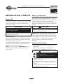
BEFORE INITIAL START-UP . . . . . . . . . . . . . . . . . . . . . . 12
Engine Oil . . . . . . . . . . . . . . . . . . . . . . . . . . . . . . . . . 12
Oil Considerations . . . . . . . . . . . . . . . . . . . . . . . 12
Battery Connection . . . . . . . . . . . . . . . . . . . . . . . . . . 12
Gaseous Fuel System . . . . . . . . . . . . . . . . . . . . . . . . 12
AUTOMATIC OPERATION . . . . . . . . . . . . . . . . . . . . . . 13
Checking Automatic Operation . . . . . . . . . . . . . . . . 13
Servicing the System . . . . . . . . . . . . . . . . . . . . . . . . . 13
Setting Exercise Timer . . . . . . . . . . . . . . . . . . . . . . . . 13
FAULT DETECTION SYSTEM . . . . . . . . . . . . . . . . . . . . . 14
Reset Fault Detection System . . . . . . . . . . . . . . 14
No LED - Discharged Battery . . . . . . . . . . . . . . 14
Low Battery Voltage . . . . . . . . . . . . . . . . . . . . . . 14
Low Oil Pressure . . . . . . . . . . . . . . . . . . . . . . . . 14
Low Voltage . . . . . . . . . . . . . . . . . . . . . . . . . . . . 15
Engine Fail To Start . . . . . . . . . . . . . . . . . . . . . . . 15
Low Frequency . . . . . . . . . . . . . . . . . . . . . . . . . . 15
Engine Overspeed . . . . . . . . . . . . . . . . . . . . . . . 15
Oil Temperature High . . . . . . . . . . . . . . . . . . . . 15
GENERATOR MAINTENANCE . . . . . . . . . . . . . . . . . . . 16
Changing Engine Oil . . . . . . . . . . . . . . . . . . . . . . . . . . 16
To Clean the Generator . . . . . . . . . . . . . . . . . . . . . . 16
When Calling the Factory . . . . . . . . . . . . . . . . . . . . . 16
STORAGE . . . . . . . . . . . . . . . . . . . . . . . . . . . . . . . . . . . . . 16
TROUBLESHOOTING . . . . . . . . . . . . . . . . . . . . . . . . . . . 17
ESPAÑOL . . . . . . . . . . . . . . . . . . . . . . . . . . . . . . . . . . 18-35
FRANÇAIS . . . . . . . . . . . . . . . . . . . . . . . . . . . . . . . . . 36-52
Copyright © 2005 Briggs & Stratton Power Products
Group, LLC. All rights reserved. No part of this material
may be reproduced or transmitted in any form by any
means without the express written permission of Briggs &
Stratton Power Products Group, LLC.

3
Briggs & Stratton Power Products Home Generator
Owners Manual
IMPORTANT SAFETY
RULES
The safety alert symbol ( ) is used with a signal word
(DANGER, CAUTION,WARNING), a pictorial and/or a
safety message to alert you to hazards. DANGER indicates
a hazard which, if not avoided, will result in death or serious
injury. WARNING indicates a hazard which, if not
avoided, could result in death or serious injury. CAUTION
indicates a hazard which, if not avoided, might result in
minor or moderate injury. CAUTION, when used
without the alert symbol, indicates a situation that could
result in equipment damage. Follow safety messages to
avoid or reduce the risk of injury or death.
The manufacturer cannot possibly anticipate every possible
circumstance that might involve a hazard.The warnings in
this manual, and the tags and decals affixed to the unit are,
therefore, not all-inclusive. If you use a procedure, work
method or operating technique that the manufacturer does
not specifically recommend, you must satisfy yourself that it
is safe for you and others.You must also make sure that the
procedure, work method or operating technique that you
choose does not render the generator unsafe.
NOTE: Your generator is equipped with a spark arrester
muffler.The spark arrester must be maintained in effective
working order by the owner/operator. In the State of
California, a spark arrester is required by law (Section 4442
of the California Public Resources Code). Other states may
have similar laws. Federal laws apply on federal lands.
Only qualified electricians and gaseous fuel
technicians should attempt installation of this
system, which must strictly comply with applicable
codes, standards and regulations.
WARNING
• Operate generator ONLY outdoors.
• Keep exhaust gas from entering a confined area through
windows, doors, ventilation intakes or other openings.
Running generator gives off carbon monoxide,
an odorless, colorless, poison gas.
Breathing carbon monoxide will cause nausea,
fainting or death.
WARNING
• DO NOT dispose of battery in a fire.
• DO NOT allow any open flame, spark, heat, or lit cigarette
during and for several minutes after charging a battery.
• DO NOT open or mutilate the battery.
• Wear protective goggles, rubber apron, and rubber gloves.
• Remove watches, rings, or other metal objects.
• Use tools with insulated handles.
Storage batteries give off explosive hydrogen gas
during recharging.
Slightest spark will ignite hydrogen and cause
explosion.
Battery electrolyte fluid contains acid and is
extremely caustic.
Contact with battery contents will cause severe
chemical burns.
A battery presents a risk of electrical shock and
high short circuit current.
DANGER
• DO NOT touch hot surfaces.
• Allow equipment to cool before touching.
• The generator enclosure must be at least 5 feet from
structures having combustible walls and/or other combustible
materials.
• Keep at least 3 feet of clearance on all sides of generator
enclosure for adequate cooling, maintenance and servicing.
Running engines produce heat.Temperature of
muffler and nearby areas can reach or exceed
150°F (65°C).
Severe burns can occur on contact.
Combustible debris, such as leaves, grass, brush,
ect. can catch fire.
WARNING
SAVE THESE INSTRUCTIONS

4
Briggs & Stratton Power Products Home Generator
Owners Manual
• DO NOT tamper with governed speed. Generator supplies
correct rated frequency and voltage when running at governed
speed.
• DO NOT modify generator in any way.
Excessively high operating speeds increase risk
of injury and damage to generator.
Excessively low speeds impose a heavy load.
CAUTION
• See “Essential Circuits” on page 7.
• Start generator and let engine stabilize before connecting
electrical loads.
Exceeding generators wattage/amperage capacity can
damage generator and/or electrical devices connected
to it.
CAUTION
• Use generator only for intended uses.
• If you have questions about intended use, ask dealer or
contact Briggs and Stratton.
• Operate generator only on level surfaces.
• Adequate, unobstructed flow of cooling and ventilating air is
critical to correct generator operation.
• The Oil Service door and/or the Control Panel door must be
installed whenever the unit is running.
• DO NOT expose generator to excessive moisture, dust, dirt,
or corrosive vapors.
• Despite the safe design of the Home Standby Generator,
operating this equipment imprudently, neglecting its maintenance
or being careless can cause possible injury or death.
• Remain alert at all times while working on this equipment.
Never work on the equipment when you are physically or
mentally fatigued.
• DO NOT start engine with air cleaner or air cleaner cover
removed.
• DO NOT insert any objects through cooling slots.
• DO NOT use the generator or any of its parts as a step.
Stepping on the unit can cause stress and break parts.This
may result in dangerous operating conditions from leaking
exhaust gases, fuel leakage, oil leakage, ect..
• If connected devices overheat, turn them off and disconnect
them from generator.
• Shut off generator if:
-electrical output is lost;
-equipment sparks, smokes, or emits flames;
-unit vibrates excessively.
Improper treatment of generator can damage it and
shorten its life.
CAUTION
• When using generator for backup power, notify utility
company.
• DO NOT touch bare wires or receptacles.
• DO NOT use generator with electrical cords which are worn,
frayed, bare or otherwise damaged.
• DO NOT handle generator or electrical cords while standing
in water, while barefoot, or while hands or feet are wet.
• If you must work around a unit while it is operating, stand on
an insulated dry surface to reduce shock hazard.
• DO NOT allow unqualified persons or children to operate or
service generator.
• In case of an accident caused by electrical shock, immediately
shut down the source of electrical power and contact the
local authorities. Avoid direct contact with the victim.
• Before performing any maintenance on the generator,
disconnect the battery cable indicated by a NEGATIVE,
NEG or (-) first.When finished, reconnect that cable last.
• After your Home Standby Generator is installed, the
generator may crank and start without warning any time there
is a power failure.To prevent possible injury, always set the
AUTO/OFF/MANUAL switch to OFF AND remove the
15 Amp fuse BEFORE working on the equipment.
Generator produces powerful voltage.
Failure to properly ground generator can result
in electrocution.
Failure to isolate generator from power utility
can result in death or injury to electric utility
workers due to backfeed of electrical energy.
WARNING
• Install the fuel supply system according to applicable fuel-gas
codes.
• Before placing the Home Standby Generator into service, the
fuel system lines must be properly purged and leak tested.
• After the generator is installed, you should inspect the fuel
system periodically.
• NO leakage is permitted.
• DO NOT operate engine if smell of fuel is present or other
explosive conditions exist.
• DO NOT smoke around the generator.Wipe up any oil spills
immediately. Ensure that no combustible materials are left in
the generator compartment. Keep the area near the generator
clean and free of debris.
Propane and Natural Gas are extremely
flammable and explosive.
Fire or explosion can cause severe burns or
death.
WARNING

5
Briggs & Stratton Power Products Home Generator
Owners Manual
SAVE THESE INSTRUCTIONS
This manual contains important instructions that should be
followed during installation and maintenance of the
generator and battery.
INTRODUCTION
Thank you for your purchase of a Briggs & Stratton Home
Standby Generator (HSG).This product is intended for use
as an optional home standby system which provides an
alternate source of electric power and to serve loads such as
heating, refrigeration systems, and communication systems
that, when stopped during any power outage, could cause
discomfort, or the like.This product DOES NOT qualify for
emergency standby as defined by NFPA 70 (NEC).
Briggs and Stratton has made every effort to provide for a
safe, streamlined and cost-effective installation. Because
each installation is unique, it is impossible to know of and
advise the trade of all conceivable procedures and methods
by which installation might be achieved. Neither could we
know of possible hazards and/or the results of each
method or procedure. For these reasons,
Only current licensed electrical and
plumbing contractors should attempt
HSG installations.
Installations must strictly comply with
all applicable codes, industry standards
and regulations.
Your Briggs & Stratton Home Standby Generator is
supplied with this “Owners Manual”, a separate “Installation
Manual” (part number 192385GS) and a Warranty Sheet
(part number 190881GS).These are important documents
and should be retained by the owner after the installation
has been completed.
Approved Transfer Switches
The Home Standby Generator should be used ONLY with
the following UL approved Transfer Switches. Connection
to any transfer switch not listed below will void your
equipment warranty.
• 50A Nema 1 enclosure, BSPP Model 01917
• 50A Nema 3R enclosure, BSPP Model 01918
• 100A Nema 3R enclosure, BSPP Model 01813
• 100A Nema 3R enclosure w/ main line disconnect, BSPP
Model 01928
• 200A Nema 3R enclosure, BSPP Model 01814
• 200A Nema 3R enclosure w/ main line disconnect, BSPP
Model 01929
Installation Assistance
For the Home or Business Owner:
To help you make informed choices and communicate
effectively with your installation contractor(s),
Read and understand the
Owner Orientation Section of this manual
BEFORE contracting or starting
your HSG installation.
To arrange for proper installation, contact the store at
which you purchased your Briggs & Stratton Home Standby
Generator, your dealer, a licensed electrician or your utility
power provider.
The HSG Warranty is VOID unless the system
is installed by licensed electrical and
plumbing professionals.
For the Installing Dealer/Contractor:
For most applications, the Installation manual contains all
the information required to properly install and start the
Home Standby Generator.This Owner’s Manual describes
essential circuit selection, routine operation and owner
maintenance procedures.
If you need more information, call 1-800-743-4115,
between 8:00 AM and 5:00 PM CT.
The Emission Control System for this generator is warranted
for standards set by the U.S. Environmental Protection Agency
and by the California Air Resources Board (CARB).
OWNER ORIENTATION
This section provides Home Standby Generator owners
with the information necessary to achieve the most
satisfactory and cost effective installation possible.
The illustrations are for typical circumstances and are
meant to familiarize you with the installation options
available with your Home Standby Generator.A thorough
understanding of these options will provide fundamental
control over the cost of your installation, as well as ensure
your final satisfaction and security.
Federal and local codes, appearance, noise levels, fuel types,
and distances are the factors that must be considered when
negotiating with an installation professional. Remember that
as the distance from the existing electrical service and
gaseous fuel supply increases, equal compensations in piping
and wiring materials must be allowed for.This is necessary
to comply with local codes and overcome electrical voltage
drops and gaseous fuel pressure drops.
The factors mentioned above will have a direct
affect on the overall price of your Home Standby
Generator installation.

6
Briggs & Stratton Power Products Home Generator
Owners Manual
NOTE: In some areas you may need to acquire electrical
permits for installing the Home Standby Generator, building
permits for installing gas lines, and permits for noise
allowances.Your installer should check your local codes
AND obtain the permits before installing the system.
Fuel Factors
An important consideration affecting the entire installation
is the type of fuel used by your Home Standby Generator.
The system was factory tested and adjusted using natural
gas as a fuel. Liquid propane (LP) may also be used as a fuel
(see the Installation Manual).
Although there are specific factors that are inherent to each
of these fuels, your location and the duration of possible
utility interruptions should guide your selection of fuel type.
For urban installations, Natural Gas (if available) should be
your fuel of choice. For remote installations, a Liquefied
Petroleum (LP) tank might better meet your needs.
For proper engine function, the following fuel guidelines are
recommended:
• Use clean, dry fuel, free of moisture or any particulate
material. Using fuels outside the following recommended
values may cause performance problems.
In engines set up to run on propane (LP) gas,
commercial grade HD5 propane with a minimum fuel
energy of 2500 BTUs/ft
3
with maximum propylene
content of 5% and butane and heavier gas content of
2.5% and minimum propane content of 90%.
Power Decrease at High Altitude or High
Temperature
Air density is less at high altitudes, resulting in less available
engine power. Specifically, engine power will decrease 3.5%
for each 1,000 feet (300 meters) above sea level and 1% for
each 10° F (5.6°C) above 77°F (25°C). Make sure you and
your installer consider these factors when determining
total generator load.
Generator Location
The actual physical location of your HSG has a direct affect
on:
1. The amount of plumbing required to fuel your generator.
2. The amount of wiring required to control and connect
your generator.
NOTE: Specific location guidelines are discussed in the
Installation Manual.Acquaint yourself with that information
and confer with your installer. Be sure to ask how your site
might affect installation costs and compliance with local
codes and standards.
Home Standby Generator Location
Before installing generator, consult with homeowner and
convey the following guidelines which may affect the
desired location.
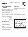
Generator Clearances
The generator enclosure must be at least 5 ft. (152 cm)
from structures having combustible walls and/or other
combustible materials. Leave at least 3 ft. (92 cm) all around
the enclosure including the roof, for adequate cooling,
maintenance and servicing.
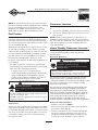
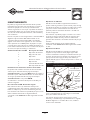
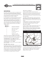
Place generator in a well ventilated area which will allow for
removal of deadly exhaust gas. DO NOT install generator
where exhaust gas could accumulate and enter inside or be
drawn into a potentially occupied building. Ensure exhaust gas
is kept away from any windows, doors, ventilation intakes or
other openings that can allow exhaust gas to collect in a
confined area (Figure 1). Prevailing winds and air currents
should be taken into consideration when positioning generator.
General Location Guidelines
• Install the unit outdoors ONLY.
• Place the unit in a prepared location that is flat and has
provisions for water drainage.
• Install the unit where air inlet and outlet openings will
not become obstructed by leaves, grass, snow, etc. If
prevailing winds will cause blowing or drifting, you may
need to construct a windbreak to protect the unit.
• The Home Standby Generator is equipped with an automatic
safety gas “fuel shut-off” valve.
• DO NOT operate the equipment if the “fuel shut-off” valve is
missing or inoperative.
Propane and Natural Gas is extremely
flammable and explosive.
Fire or explosion can cause severe burns or
death.
WARNING
• Operate generator ONLY outdoors.
• Keep exhaust gas from entering a confined area through
windows, doors, ventilation intakes or other openings.
Running generator gives off carbon monoxide,
an odorless, colorless, poison gas.
Breathing carbon monoxide will cause nausea,
fainting or death.
WARNING

7
Briggs & Stratton Power Products Home Generator
Owners Manual
• Install the generator as close as possible to the Transfer
Switch to reduce the length of wiring and conduit.
• Install the generator as close as possible to the fuel
supply to reduce length of pipes.
IMPORTANT: Laws or local codes may regulate the
distance to the fuel supply.
The Home Standby Generator is shipped already attached
to its mounting pad. Unless mandated by local code, a
concrete slab is not required.
If mandated by local code, construct a concrete slab at least
3 inches thick and 6 inches longer and wider than the unit.
Attach unit to slab with 1/4” diameter (minimum) masonry
anchor bolts long enough to retain the unit.
Essential Circuits
As a Home Standby Generator owner, it is important that
you clearly identify the circuits in your building that are
"essential" to you.
It is important that your installer understand which
circuits
you want to include as "Essential Circuits". Depending on
the power consumed by these circuits, most or all of them
can be switched to the Home Standby Generator for the
duration of normal power interruption.
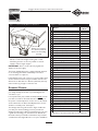
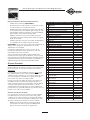
The wattage reference guide shown in Figure 2 will assist
you with your decision-making process. It provides the
wattage used by many ordinary household devices. Use it as
a guide when selecting your essential circuits. Review this
information with your installer and ask about any technical
considerations that might affect the cost of your installation.
Figure 1 — Home Standby Generator Clearances
Exhaust port must be
5 ft (152 cm) minimum
distance from building
openings
Exhaust
Port
Device
Running
Watts
Air Conditioner (12,000 Btu)*
1700
Air Conditioner (24,000 Btu)*
3800
Air Conditioner (40,000 Btu)*
6000
Battery Charger (20 Amp)
500
Circular Saw (6-1/2")
800 to 1000
Clothes Dryer (Electric)*
5750
Clothes Dryer (Gas)*
700
Clothes Washer*
1150
Coffee Maker
1750
Compressor (1 HP)*
2000
Compressor (1/2 HP)*
1400
Compressor (3/4 HP)*
1800
Curling Iron
700
Dehumidifier*
650
Electric Blanket
400
Electric Range (per element)
1500
Electric Skillet
1250
Freezer*
700
Furnace Fan (3/5 HP)*
875
Garage Door Opener*
500 to 750
Hair Dryer
1200
Hand Drill
250 to 1100
Iron
1200
Jet Pump*
800
Light Bulb
100
Microwave Oven
700 to 1000
Milk Cooler*
1100
Oil Burner on Furnace
300
Oil Fired Space Heater (140,000 Btu)
400
Oil Fired Space Heater (30,000 Btu)
150
Oil Fired Space Heater (85,000 Btu)
225
Radio
50 to 200
Refrigerator
700
Slow Cooker
200
Submersible Pump (1 HP)*
2000
Submersible Pump (1/2 HP)*
1500
Submersible Pump (1-1/2 HP)*
2800
Sump Pump*
800 to 1050
Table Saw (10")*
1750 to 2000
Television
200 to 500
Toaster
1000 to 1650
Figure 2 — Wattage Reference Guide
*Allow three (3) times listed watts for starting device

8
Briggs & Stratton Power Products Home Generator
Owners Manual
Essential Circuit Selection
When selecting the essential circuits that will be switched to
“Standby Power,” it is important that the sum of the combined
circuit loads does not exceed the wattage/amperage capacity
of the generator.To help you with your selection of essential
circuits, please consider the following:
Add up the total wattage of all electrical devices to be
connected at one time.This total should NOT be
greater than the generator’s wattage capacity.
The rated wattage of lights can be taken from light bulbs.
The rated wattage of tools, appliances and motors can
usually be found on a data plate or decal affixed to the
device.
If the appliance, tool or motor does not give wattage,
multiply 120 Volts times the ampere rating to determine
watts (Volts x Amps = Watts).
Some electric motors (induction types) require about
three times more watts of power for starting than for
running.This surge lasts for only a few seconds. Be sure
you allow for this high starting wattage when selecting
electrical devices that will be energized by the Home
Standby Generator:
• Figure the watts required to start the largest motor.
• Add that to the total running watts of all other
connected loads.
This Briggs & Stratton Home Standby Generator
complies with the following “stationary standby
power rating”:
The standby power rating is applicable for supplying power
for the duration of normal power interruption. NO
sustained overload capability is available for this rating.
This rating is applicable to installations served by a
reliable normal utility source.This rating is only applicable
to variable loads with an average load factor of 80% of
the standby rating.The standby rating is only applicable
for optional standby power where the generator set
serves as the backup to the normal utility source.
Use the “Wattage Reference Guide” provided and mark
those circuits you consider “critical” or “essential”. Make
sure you and your installer consider the system’s altitude
above sea level and the ambient temperature range when
determining total generator load.
IMPORTANT:When using the 100 Amp or 200 Amp
transfer switch with the Home Standby Generator, you must
turn off any non essential loads. Failure to turn off non
essential loads could overload the generator causing it to shut
down. Some examples of non essential loads are as follows:
• Pool pump
• Hot tub
• Electric hot tub and/or pool heaters
• Central air conditioners
• Electric hot water heaters
• Electric range and/or oven
• Arc welder
• Non essential electric heaters
UNPACKING
Refer to the Installation Manual for detailed unpacking
instructions, if desired.
Delivery Inspection
After removing the carton, carefully inspect the Home
Standby Generator for any damage that may have occurred
during shipment.
IMPORTANT: If loss or damage is noted at time of
delivery, have the person(s) making delivery note all damage
on the freight bill and affix his signature under the
consignor's memo of loss or damage. If loss or damage is
noted after delivery, separate the damaged materials and
contact the carrier for claim procedures. Missing or
damaged parts are not warranted.
Shipment Contents
The Home Standby Generator is supplied with:
• Home standby generator
• Attached mounting pad
• One 24” flexible fuel hook-up hose
• Installation manual (P/N 192385GS)
• Owner’s manual (P/N 192384GS)
• Illustrated parts list manual (P/N 193208GS for
model 01815 or P/N 193918GS for model 01938)
• Product warranty sheet (P/N 190881GS)
• Installation checklist (P/N 190840GS)
• Three access door keys
• Four lifting hole plugs
• Oil fill spout
• Touch-up paint
• One spare 15 Amp fuse
• Diagnostic LED kit (diode/plate/decal/pin connectors (2))

9
Briggs & Stratton Power Products Home Generator
Owners Manual
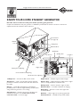
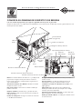
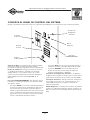
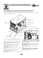
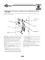
KNOW YOUR HOME STANDBY GENERATOR
Read this owner’s manual and safety rules before operating your generator.
Compare the illustrations with your generator to familiarize yourself with the locations of various controls and
adjustments. Save this manual for future reference.
15 Amp Fuse — Protects the DC control circuits.
Air Cleaner — Uses a dry type filter element and foam
precleaner to limit the amount of dirt and dust drawn into
the engine.
Battery — 12 Volt DC, 33 Amp-Hour sealed battery
provides power to start the engine. Battery receives trickle
charge whenever generator is not running.
Control Panel — Used for various test, operation and
maintenance functions. See “KNOW YOUR SYSTEM
CONTROL PANEL” on the next page.
Engine Label — Identifies engine model and type.
Exhaust Port — High-performance muffler lowers engine
noise to comply with most residential codes.
Oil Dip Stick — Used to check the engine oil level.
Oil Drain Hose — Provided to facilitate oil changing.
Oil Fill Cap — Remove to service the engine with
recommended oil.
Oil Filter — Filters engine oil to prolong system life.
Unit Data Decal — Identifies unit by serial number.
Air Cleaner
Oil
Filter
Battery Door Opening
Control Panel Door Opening
Unit
Data
Decal
Oil Service Door Opening
Exhaust
Port
Oil Dip Stick
Fuel Inlet
Control Panel
(see page 10)
Battery
Oil Drain Hose
Oil Fill Cap
15 Amp Fuse
Engine Label

10
Briggs & Stratton Power Products Home Generator
Owners Manual
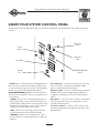
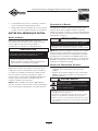
KNOW YOUR SYSTEM CONTROL PANEL
Compare this Control Panel illustration with your generator to familiarize yourself with the location of these important
controls:
Hour Meter
Circuit
Breaker
Set Exercise
Switch
AUTO/OFF/MANUAL
Switch
Diagnostic
LED
15 Amp
Fuse
15 Amp Fuse — Protects the Home Standby Generator
DC control circuits. If the fuse has ‘blown’ (melted open)
or was removed, the engine cannot crank or start. Replace
the fuse using only an identical BUS AGC 15A fuse.
AUTO/OFF/MANUAL Switch — This three-position
switch is the most important control on the system and is
used as follows:
•“AUTO” position is the normal operating position. If a
utility power outage is sensed, the system will start the
generator.When utility power is restored, lets the engine
stabilize internal temperatures, shuts off the generator,
and waits for the next utility power outage.
•“OFF” position turns off running generator, prevents
unit from starting and resets any detected faults.
•“MANUAL” position starts the engine after a short
amount of time. It is used for maintenance or diagnostic
functions.
Circuit Breaker — Protects the system from shorts and
other over-current conditions. Must be ON to supply
power to the Automatic Transfer Switch.
Diagnostic LED — Used for troubleshooting operational
problems with the Home Standby Generator.All fault
conditions are described in the section “Fault Detection
System”.
Hour Meter — The hour meter records the total number
of hours the generator has been running and is used to
schedule maintenance tasks.
Set Exercise Switch — Used to set the exercise cycle
start time and day-of-the-week. Exercise cycle only occurs
in AUTO mode.

11
Briggs & Stratton Power Products Home Generator
Owners Manual
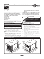
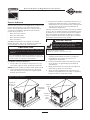
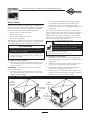
Access Doors
The Home Standby Generator is equipped with an
enclosure that has four access doors (Figure 3).The doors
are named for a significant component located behind
them. Starting with the side that has the fuel connection
and proceeding clockwise, the doors are named:
• Oil Service door
• Air Intake door
• Control Panel door
• Battery door
Each Home Standby Generator is equipped with three
identical keys.These keys fit the locks that secure the Oil
Service and Control Panel doors.
To Remove an Access Door:
1. Insert key into lock of access door you wish to
remove and turn one quarter turn clockwise.
NOTE: The key is retained in the lock when the locks are
open.
2. Grasp door’s lift handle and pull door upwards until
security pins are free of lower base.
3. With security pins free, pull lift handle outward (away)
from unit while pulling door down and out of upper
door channel.The door will come free of generator
enclosure.
The Battery door does not have a lock and the Air Intake
door does not have a lock or lift handle.The Air Intake
door is opened by lifting on the louvers instead of a lift
handle. However, you must remove the door lock screws,
found directly above the center of the doors.
To Install an Access Door:
1. Support door by grasping lift handle or louver. Guide
top of door into generator enclosure.
2. Lift door up into its upper channel until security pins
clear sill of enclosure.
3. Push lower half of door into door recess until it is
flush with sides.
4. Seat door by pushing it down until rubber coated
security pins engage and door rests on mounting sill.
5. If installing a lockable door, turn key one quarter turn
counterclockwise. Remove key.
6. If installing air intake or battery door, replace the door
lock screw.
Oil Service Door
Fuel
Inlet
Exhaust
Port
Air Intake Door
Door Lock
Screw
Door
Lock
Screw
Battery Door
Control Panel Door
Figure 3 — Enclosure Access Doors
CAUTION
• Failure to install Oil Service and/or Control Panel doors while
operating the Home Standby Generator will cause overheating.
DO NOT operate the Home Standby Generator unless
the Oil Service and/or Control Panel doors are installed.
• DO NOT touch hot surfaces.
• Allow equipment to cool before touching.
Running engines produce heat.Temperature of
exhaust port and nearby areas can reach or
exceed 600°F (316°C).
Severe burns can occur on contact.
WARNING

12
Briggs & Stratton Power Products Home Generator
Owners Manual
BEFORE INITIAL START-UP
Engine Oil
This engine is shipped from the factory filled with the
recommended oil. Before starting the engine, check oil level
and ensure that engine is serviced as described in the
engine owner’s manual.
Oil Considerations
Your Home Standby Generator is equipped with an engine
that has been pre-run at the factory and does not require
the traditional “break-in” procedure.
The system is filled with synthetic oil (API SJ/CF 5W-30W).
This allows for system operation in the widest range of
temperature and climate conditions.
NOTE: The use of synthetic oil DOES NOT alter the
required oil change intervals described in the engine
owner’s manual.
Battery Connection
The Home Standby Generator is supplied with a 12Volt
DC 33 Amp-Hour, valve regulated battery. It is a sealed,
lead-acid rechargeable battery. It is installed in the unit and
the battery cables are connected at the factory.The
generator’s 15 Amp fuse has been removed to prevent the
battery from discharging and the unit from starting during
shipping.
NOTE: With the battery installed, all wiring to transfer
switch and Home Standby Generator completed, utility
power supplied to the Automatic Transfer Switch, and the
unit in AUTO mode, the battery receives a trickle charge
while the engine is not running.The trickle charger cannot
be used to recharge a battery that is completely
discharged.
Gaseous Fuel System
• Ensure that all fuel connections are tight, secure and
without leaks.
• Ensure that all shutoff valves are OPEN and that
adequate pressure is available (see installation manual).
CAUTION
• Refer to engine manual for oil fill information.
• Damage to equipment resulting from failure to follow this
instruction will void warranty.
Any attempt to crank or start the engine before it has
been properly serviced with the recommended oil will
result in equipment failure.
• DO NOT install the 15 Amp fuse until all plumbing and wiring
has been completed and inspected.
Installing the 15A fuse could cause the engine to start.
CAUTION
• DO NOT operate engine if smell of fuel is present or other
explosive conditions exist.
• If you smell ‘raw’ gaseous fuel (natural or LP) near the unit,
immediately turn off the gas supply to the Home Standby
Generator.
• Contact your gas utility or the system installer for assistance
in determining the source of the smell.
Propane and Natural Gas is extremely
flammable and explosive.
Fire or explosion can cause severe burns or
death.
WARNING

13
Briggs & Stratton Power Products Home Generator
Owners Manual
AUTOMATIC OPERATION
To select automatic operation, do the following:
1. Set the service disconnect or main distribution panel
circuit breaker that sends utility voltage to the transfer
switch to ON.
2. Set the generator’s main circuit breaker to its ON
position.
3. Set the AUTO/OFF/MANUAL switch to AUTO.
Checking Automatic Operation
To check the system for proper automatic operation,
proceed as follows:
1. Turn OFF the service disconnect or main distribution
panel circuit breaker sending power to the automatic
transfer switch.
The engine will crank and start once the utility voltage
drops out and the sensor has timed out. Let the system go
through its entire automatic operation sequence.
2. With the generator output supplying its loads, turn
ON the service disconnect or main distribution panel
circuit breaker that supplies utility power to the
Automatic Transfer Switch.
3. The automatic transfer switch will transfer loads back
to the utility power after 5 minute minimum run time
and utility is restored.
4. The generator will run for an additional one minute for
engine cool down, then shut down.
NOTE: If generator does not shut down after 10 minutes,
put AUTO/OFF/MANUAL switch to OFF and contact your
installer or local service center.
This completes the test procedures for automatic
operation.The Home Standby Generator will now start
automatically when utility power is lost and will supply
power to the transfer switch.
Servicing the System
To service system:
1. Set the AUTO/OFF/MANUAL switch to OFF.
2. Set the generator’s main circuit breaker to its OFF
position.
3. Utility voltage is present. Disconnect power before
servicing by removing the two 2 Amp fuses from the
transfer switch.
Setting Exercise Timer
The Home Standby Generator is equipped with an exercise
timer that will start and exercise the system once every
seven days. During this exercise period, the unit runs for
approximately 20 minutes and then shuts down. Electrical
load transfer DOES NOT occur during the exercise cycle
(unless an utility power outage occurs).
A switch on the control panel is labeled “Set Exercise”
(depicted on page 10).The specific day and the specific time
of day this switch is pressed is programmed into the
control board memory.This date and time is then used to
automatically initiate the system exercise cycle.
To perform the Set Exercise procedure:
1. Choose the day and time you want your Home
Standby Generator to exercise.
2. On that da
y and time, set the AUTO/OFF/MANUAL
switch to OFF.
3. Press and hold down the “Set Exercise” switch for two
seconds.
4. Set the AUTO/OFF/MANUAL switch to AUTO.“Set
Exercise” is complete.
For example, if you press the “Set Exercise” switch on
Sunday morning at 10:00 AM, the unit will run an exercise
cycle the following Sunday at 10:00 AM (+/- 1/2 hour).
NOTE: “Set Exercise” will only work if the unit is in the
Automatic mode and this exact procedure is followed.The
exerciser does not need to be re-set if the 15 Amp fuse is
removed or changed.The exerciser will need to be re-set if
the 12 Volt DC battery is disconnected.
If you want to change the day and time the unit exercises,
simply perform the “Set Exercise” procedure at the exact
weekday and time you want it to take place.
• To prevent possible injury that might be caused by such sudden
starts, always set the AUTO/OFF/MANUAL switch to OFF.
• Remove the 15 Amp fuse before working on or around the
generator or transfer switch.
With the switch set to AUTO, the engine may crank
and start at any time without warning. Such automatic
starting normally occurs when utility source voltage
drops below a preset level or during the normal
exercise cycle.
CAUTION

14
Briggs & Stratton Power Products Home Generator
Owners Manual
FAULT DETECTION
SYSTEM
The generator may have to run for long periods of time
with no operator present. For that reason, the system is
equipped with sensors that automatically shut down the
generator in the event of potentially damaging conditions,
such as low oil pressure, high oil temperature, over speed,
and other conditions.
A light on the generator's control panel is called the
Diagnostic LED.A similar LED indicator is installed at a
convenient inside location. Both LED's will turn on and off
in the same series of blinks if certain problems are
detected in your HSG.The blink pattern is repeated with a
brief pause between each series.The number of blinks in
the series indicates the detected fault, as listed near the
control panel, on the mounting plate and as follows:
Number of LED Flashes Fault Description
1 Low battery voltage
2 Low oil pressure
3 Low voltage
4 Engine fail to start
5 Low frequency
6 Engine overspeed
7 Oil temperature high
Reset Fault Detection System
The operator must reset the fault detection system each
time it activates.To do so, place the AUTO/OFF/MANUAL
switch in the OFF position for 30 seconds or more.
Return the Home Standby Generator to service after
correcting the problem by placing the
AUTO/OFF/MANUAL switch in the AUTO position.
A description of each fault and suggested remedies are as
follows:
No LED - Discharged Battery
This condition is caused by a completely discharged
battery.To remedy the problem, remove the 15 Amp fuse
and disconnect the battery from the generator.Take the
battery to a local battery store for analysis.
Replace the battery after it has been fully recharged,
connecting the NEGATIVE cable last. Install the 15 Amp
fuse.
Low Battery Voltage
This fault is indicated by one blink.This condition occurs if
the generator cannot start because the starting battery
output power is below that needed to crank the engine.
Causes for this problem may be a faulty battery or trickle
charger circuit.
To remedy the problem, contact your local service center
to check the battery trickle charge output. Remove the
15 Amp fuse and disconnect the battery from the generator.
Take the battery to a local battery store for analysis.
Replace the battery after it has been fully recharged,
connecting the NEGATIVE cable last. Install the 15 Amp fuse.
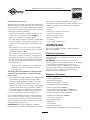
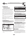
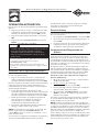
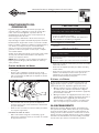
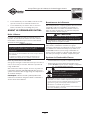
Low Oil Pressure
This fault is indicated by two blinks.The unit is equipped
with an oil pressure switch (Figure 4) using normally closed
contacts that are held open by engine oil pressure during
operation. Should oil pressure drop below the 8 psi range,
switch contacts close and the engine is shut down.
To remedy the low oil pressure condition, add the
recommended oil to the FULL mark on the dipstick.
If low oil pressure condition still exists, engine will start,
then shut down after about 10 seconds and diagnostic LED
will flash. In this case, contact an authorized service facility.
Figure 4 — Low Oil Pressure & High Temp. Switches
High
Temperature
Switch
Oil Drain
Fitting
Oil
Pressure
Switch

15
Briggs & Stratton Power Products Home Generator
Owners Manual
Low Voltage (Generator)
This fault is indicated by three blinks.This condition is
caused by a restriction in the fuel flow, a broken or
disconnected signal lead, a failed alternator winding, the
control panel circuit breaker is open, or Home Standby
Generator is overloaded.
To remedy the problem, contact your local service center.
Engine Fail To Start
This fault is indicated by four blinks.This feature prevents
the generator from damaging itself if it continually attempts
to start in spite of another problem, such as no fuel supply.
Each time the system is directed to start, the unit will
crank for 15 seconds, pause for 15 seconds, crank for
15 seconds, pause for 15 seconds, and repeat. If the system
does not begin producing electricity after approximately
90 seconds, the unit will stop cranking and the LED will
blink.
The most likely cause of this problem is no fuel supply.
Check the inside and outside fuel shut off valves to ensure
they are fully open. Other causes could be failed spark
plug(s), failed engine ignition, or the engine air filter is
clogged.You may need to contact your installer for
assistance if you can’t remedy these problems.
Low Frequency
This fault is indicated by 5 blinks.This feature protects
devices connected to the transfer switch by shutting the
generator down if the engine runs slower than the preset
limit.
This condition is caused by a failed engine governor or by
excessive loads on the generator.To remedy the problem,
you may need to contact your installer or local service
center for assistance.
Engine Overspeed
This fault is indicated by 6 blinks.This feature protects
devices connected to the transfer switch by shutting the
generator down if the engine happens to run faster than
the preset limit.The overspeed fault is detected as follows:
• If the generator output frequency runs at 72 Hz for five
seconds, the generator will shut down.
• If the generator output frequency reaches 75 Hz, the
generator will shut down instantly.
This condition is caused by a failed engine governor.To
remedy the problem, you should contact your installer or
local service center for assistance.
Oil Temperature High
This fault is indicated by seven blinks.The contacts of the
temperature switch (Figure 4) are normally open. If the
engine oil temperature exceeds approximately 140°C
(284°F), the fault is detected and the engine shuts down.
Common causes for this condition include running the unit
with all access doors removed, obstructed air inlet or
exhaust port, low oil level, or debris in the engine cylinder
cooling fins.
To resolve the problem, remove any accumulated debris
and obstructions and let the engine cool down. Ensure that
the Oil Service door and/or the Control Panel door is
installed whenever the unit is running.

16
Briggs & Stratton Power Products Home Generator
Owners Manual
GENERATOR
MAINTENANCE
The generator warranty does not cover items that have
been subjected to operator abuse or neglect.To receive full
value from the warranty, the operator must maintain the
system as instructed in the engine owner’s manual.
All adjustments should be made at least once each season.
Follow the requirements in the engine owner’s manual.
Generator maintenance consists of keeping the unit clean.
Operate the unit in an environment where it will not be
exposed to excessive dust, dirt, moisture or any corrosive
vapors. Cooling air louvers on the enclosure must not
become clogged with snow, leaves, or any other foreign
material.
Check the cleanliness of the unit frequently and clean when
dust, dirt, oil, moisture or other foreign substances are
visible on its exterior/interior surface.
NOTE: DO NOT use direct spray from a garden hose to
clean generator.Water can enter the engine and generator
and cause problems.
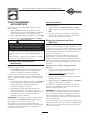
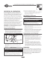
Changing Engine Oil
• Place the oil drain tube into an approved container.
• Push in and rotate the oil drain fitting 1/4 turn
counterclockwise. Slowly pull outward until oil starts
draining (Figure 5). DO NOT pull the oil drain fitting off
the engine.
• When the oil has drained, push the oil drain fitting in and
rotate 1/4 turn clockwise until it locks in place.
• Slide the oil drain tube up into the clamp on the
generator.
To fill your engine with oil:
• Follow the synthetic oil grade recommendation and oil
fill instructions given in the engine owner’s manual.
To Clean the Generator
• Use a damp cloth to wipe exterior surfaces clean.
• Use a soft, bristle brush to loosen caked on dirt, oil, etc.
• Use a vacuum cleaner to pick up loose dirt and debris.
• Use low pressure air (not to exceed 25 psi) to blow away
dirt. Inspect cooling air slots and openings on the generator.
These openings must be kept clean and unobstructed.
When Calling the Factory
You must have the following information at hand if it is
necessary to contact a local service center regarding
service or repair of this unit:
1. Obtain the unit Model Number and Serial Number
from the unit data decal. See “Know Your Backup
Generator” diagram for location.
2. Obtain the engine Model/Type/Code numbers from the
engine label. See “Know Your Backup Generator”
diagram for location. Please note that the model
number may vary slightly from that presented herein.
STORAGE
The Briggs & Stratton Home Standby Generator is
designed for continuous backup operational duty.As such,
there is no need to take any storage precautions. However,
if it becomes necessary to take the system out of service
for an extended period, call Briggs and Stratton Technical
Services at 1-800-743-4115, between 8:00 AM and 5:00 PM
CT for specific recommendations.
Figure 5 — Oil Drain Fitting
CAUTION
• Refer to engine manual for oil fill information.
• Damage to equipment resulting from failure to follow this
instruction will void warranty.
Any attempt to crank or start the engine before it has
been properly filled with the recommended oil will result
in equipment failure.
• DO NOT expose generator to excessive moisture, dust, dirt,
or corrosive vapors.
• DO NOT insert any objects through cooling slots.
Improper treatment of generator can damage it and
shorten its life.
CAUTION

17
Briggs & Stratton Power Products Home Generator
Owners Manual
TROUBLESHOOTING
Problem Cause Correction
Engine is running, but no AC
output is available.
1. Circuit breaker open or defective.
2. Fault in generator.
3. Poor wiring connections or
defective transfer switch.
1. Reset or replace circuit breaker.
2. Contact local service facility.
3. Check and repair.
Engine runs good at no-load but
"bogs down" when loads are
connected.
1. Short circuit in a connected load.
2. Generator is overloaded.
3. Shorted generator circuit.
4. Fuel Pressure is incorrect.
5. Natural gas fuel mixture is
incorrect.
1. Disconnect shorted electrical load.
2. See "Essential Circuits".
3. Contact local service facility.
4. See "The Gaseous Fuel System" in
the Installation Manual.
5. See "The Gaseous Fuel System" in
the Installation Manual.
Engine will not start; or starts and
runs rough.
1. 15 Amp fuse missing or blown.
2. Out of fuel.
3. Failed battery.
1. Install (new) 15 Amp fuse. See
“Know Your System Control
Panel”.
2. Open fuel valve(s); check propane
tank.
3. Replace battery.
Engine shuts down during
operation.
1. Out of fuel.
2. Fault indicator blinking.
1. Check fuel valves, fill propane tank.
2. Count blinks and refer to "Fault
Detection System".
Loss of power on essential
circuits.
1. Generator circuit breaker is open.
2. Transfer switch problems.
1. Reset circuit breaker.
2. See the transfer switch manual.

Generador Doméstico de Briggs & Stratton Power Products
Manual del Propietario
18
TABLA DE CONTENIDO. . . . . . . . . . . . . . . . . . . . . . . . . . . . . . 18
REGLAS DE SEGURIDAD . . . . . . . . . . . . . . . . . . . . . . . . . . . 19-20
INTRODUCCIÓN . . . . . . . . . . . . . . . . . . . . . . . . . . . . . . . . . . . . 21
Conmutadores de Transferencia Aprobados . . . . . . . . . . . . 21
Asistencia para la Instalación . . . . . . . . . . . . . . . . . . . . . . . . 21
Para el Propietario Comercial o Doméstico. . . . . . . . 21
Para el Agente de Ventas/Contratista. . . . . . . . . . . . . . 21
ORIENTACIÓN PARA EL PROPIETARIO . . . . . . . . . . . . . . . . . 21
Factores Relacionados con el Combustible . . . . . . . . . . . . 22
Disminución de la Potencia a Temperaturas Elevadas o
en Lugares Altos . . . . . . . . . . . . . . . . . . . . . . 22
Ubicación del Generador. . . . . . . . . . . . . . . . . . . . . . . . . . . 22
Distancias Desde el Generador . . . . . . . . . . . . . . . . . . . 22-23
Circuitos Fundamentales . . . . . . . . . . . . . . . . . . . . . . . . . . . 23
Selección de los Circuitos Fundamentales . . . . . . . 23-24
DESEMPAQUE . . . . . . . . . . . . . . . . . . . . . . . . . . . . . . . . . . . . . . . 24
Inspección al Momento de la Entrega . . . . . . . . . . . . . . . . . 24
Contenido de la Caja . . . . . . . . . . . . . . . . . . . . . . . . . . . . . . 24
CONOZCA SU GENERADOR DOMÉSTICO . . . . . . . . . . . . . 25
CONOZCA EL PANEL DE CONTROL DEL SISTEMA . . . . . . 26
Puertas de Acceso . . . . . . . . . . . . . . . . . . . . . . . . . . . . . . . . 27
Para Retirar una Puerta de Acceso . . . . . . . . . . . . . . . 27
Para Instalar una Puerta de Acceso . . . . . . . . . . . . . . . 27
ANTES DEL ARRANQUE INICIAL. . . . . . . . . . . . . . . . . . . . . . . 28
Aceite de Motor. . . . . . . . . . . . . . . . . . . . . . . . . . . . . . . . . . 28
Consideraciones Sobre el Aceite. . . . . . . . . . . . . . . . . 28
Conexión de la Batería . . . . . . . . . . . . . . . . . . . . . . . . . . . . 28
Sistema de Combustible Gaseoso . . . . . . . . . . . . . . . . . . . . 28
OPERACIÓN AUTOMÁTICA . . . . . . . . . . . . . . . . . . . . . . . . . . . 29
Verificación de la Operación Automática . . . . . . . . . . . . . . 29
Paro del Sistema. . . . . . . . . . . . . . . . . . . . . . . . . . . . . . . . . . 29
Configuración del Temporizador de Práctica . . . . . . . . . . . 29
MANTENIMIENTO . . . . . . . . . . . . . . . . . . . . . . . . . . . . . . . . . . . 30
Restablecimiento del Sistema de Detección de Fallas 30
No se Enciende el LED - Batería Descargada. . . . . . . 30
Baja Tensión de la Batería. . . . . . . . . . . . . . . . . . . . . . . 30
Baja Presión de Aceite . . . . . . . . . . . . . . . . . . . . . . . . . 30
Baja Tensión. . . . . . . . . . . . . . . . . . . . . . . . . . . . . . . . . . 31
El Motor no Arranca . . . . . . . . . . . . . . . . . . . . . . . . . . 31
Baja Frecuencia. . . . . . . . . . . . . . . . . . . . . . . . . . . . . . . 31
Sobrevelocidad del Motor . . . . . . . . . . . . . . . . . . . . . . 31
Alta Temperatura del Aceite. . . . . . . . . . . . . . . . . . . . . 31
MANTENIMIENTO DEL GENERADOR. . . . . . . . . . . . . . . . . . . 32
Cambio del Aceite del Motor . . . . . . . . . . . . . . . . . . . . . . . 32
Para Limpiar el Generador. . . . . . . . . . . . . . . . . . . . . . . . . . 32
Si Llama a la Fábrica . . . . . . . . . . . . . . . . . . . . . . . . . . . . . . . 32
ALMACENAMIENTO. . . . . . . . . . . . . . . . . . . . . . . . . . . . . . . . . . 32
NOTAS. . . . . . . . . . . . . . . . . . . . . . . . . . . . . . . . . . . . . . . . . 33 & 34
REPARACION DE AVERIAS . . . . . . . . . . . . . . . . . . . . . . . . . . . . 35
TABLA DE CONTENIDO

Generador Doméstico de Briggs & Stratton Power Products
Manual del Propietario
19
INSTRUCCIONES IMPORTANTES
DE SEGURIDAD
El símbolo de alerta de seguridad ( ) es usado con una palabra
(PELIGRO,ADVERTENCIA, PRECAUCIÓN), un mensaje por
escrito o una ilustración, para alertarlo acerca de cualquier
situación de peligro que pueda existir. PELIGRO indica un riesgo
el cual, si no se evita, causará la muerte o una herida grave.
ADVERTENCIA indica un riesgo el cual, si no se evita, puede
causar la muerte o una herida grave. PRECAUCIÓN indica un
riesgo, el cual, si no se evita, puede causar heridas menores o
moderadas. PRECAUCIÓN, cuando se usa sin el símbolo de
alerta, indica una situación que podría resultar en el daño del
equipo. Siga los mensajes de seguridad para evitar o reducir los
riesgos de heridas e inclusive la muerte.
El fabricante no puede prever todas las posibles circunstancias que
pueden implicar riesgos. Por lo tanto, las advertencias que
aparecen en este manual y las etiquetas y calcomanías adheridas a
la unidad no incluyen todas las posibilidades. Si aplica un
procedimiento, método de trabajo o técnica de operación no
recomendada específicamente por el fabricante, debe estar seguro
de que se trata de una práctica segura para usted y para otras
personas.También debe asegurarse de que el procedimiento,
método de trabajo o técnica de operación que elija, no haga que
el generador se torne inseguro.
NOTA: El generador viene equipado con un silenciador del
escape con amortiguador de chispas. El operador o el propietario
debe mantener el amortiguador de chispas en perfectas
condiciones de funcionamiento. En el estado de California, el
amortiguador de chispas es un elemento requerido por la ley
(Sección 4442 del California Public Resources Code). Otros
estados pueden tener leyes similares. En los territorios federales
se aplican las leyes federales.
Únicamente los electricistas capacitados y los técnicos
especializados en combustibles gaseosos pueden
intentar instalar este sistema. Dicha instalación debe
cumplir estrictamente con los códigos, las regulaciones y
las normas correspondientes.
ADVERTENCIA
• Opere el generador SOLAMENTE al aire libre.
• Evite que los gases de escape entren en un espacio cerrado a través
de las ventanas, puertas, tomas de aire de ventilación u otras
aberturas.
Al generador funcionar, se produce monóxido de
carbono, un gas inodoro y venenoso.
El respirar el monóxido de carbono, producirá
náusea, desmayo o la muerte.
ADVERTENCIA
• NO deseche la batería tirándola al fuego.
• NO permita ninguna llama abierta, chispa, calor, o encienda un
cigarrillo durante y por varios minutos después de haber recargado la
batería.
• NO abra ni manipule la batería.
• Lleve puestos las gafas protectoras, delantal y guantes de goma.
• No lleve relojes, anillos ni otros objetos metálicos.
• Utilice herramientas con mangos aislados.
Las baterías almacenadas producen hidrógeno
explosivo mientras estén siendo recargadas.
Una pequeña chispa puede encender el hidrógeno y
causar una explosión.
El fluido de electrolito de la batería contiene ácido y
es extremadamente cáustico.
El contacto con el fluido de la batería puede causar
quemaduras químicas severas.
Las baterías presentan un riesgo de descarga eléctrica
y de elevada corriente de cortocircuito.
PELIGRO
• NO toque las superficies calientes.
• Permita que el equipo se enfríe antes de tocarlo.
• La carcasa del generador debe estar situada a un mínimo de 5 pies de
toda estructura con muros combustibles
y/o otras materias
combustibles.
• Mantenga al menos 3 pies de espacio libre alrededor del generador,
para la adecuada ventilación
y el mantenimiento del generador.
Los motores al funcionar producen calor. La
temperatura del silenciador y de las áreas cercanas
puede alcanzar o pasar los 150ºF (65ºC).
Quemaduras severas pueden ocurrir al hacer
contacto.
Los residuos como hojas, hierba, maleza, etc. se
pueden inflamar.
ADVERTENCIA
CONSERVE ESTAS INSTRUCCIONES

Generador Doméstico de Briggs & Stratton Power Products
Manual del Propietario
20
• NO cambie ninguna velocidad determinada. El generador suministra
una frecuencia y un voltaje calificado cuando funciona a una velocidad
determinada.
• NO modifique al generador en ninguna forma.
Las velocidades de operación en exceso, aumentan
los riesgos de heridas y daños al generador.
Las velocidades bajan en exceso, imponen una carga
muy pesada.
PRECAUCIÓN
• Vea "Circuitos Fundamentales" en la página 23.
• Encienda su generador y deje que el motor se estabilice antes de
conectar las cargas eléctricas.
El sobrepasar la capacidad del amperaje y vataje del
generador, puede dañar al generador y los aparatos eléctricos
conectados al mismo.
PRECAUCIÓN
• Use el generador solamente con la finalidad para el cual fue diseñado.
• Si usted tiene alguna pregunta acerca de las finalidades de uso del
generador, pregúntele a su concesionario o contacte a Briggs and
Stratton.
• Opere el generador solamente en superficies niveladas.
• Para la correcta operación del generador es fundamental contar con
ventilación y una circulación de aire de refrigeración adecuada y que
no sufra obstrucciones.
• La puerta de servicio del aceite o la del panel de control deben estar
instaladas siempre que la unidad esté en funcionamiento.
• NO exponga al generador a una humedad excesiva, polvo, suciedad o
vapores corrosivos.
• A pesar del diseño seguro del Generador Doméstico, si se opera este
equipo en forma imprudente, si no se cumple con el mantenimiento o
si se actúa con descuido, se pueden producir lesiones o la muerte.
• Permanezca siempre alerta cuando trabaje con este equipo. Nunca
trabaje con este equipo si se siente cansado física o mentalmente.
• NUNCA encienda el motor si el filtro de aire o su cubierta han sido
retirados.
• NO inserte cualquier objeto a través de las ranuras de enfriamiento.
• NUNCA utilice el generador ni ninguna de sus piezas como escalera.
Si se sube sobre la unidad, sus piezas se pueden ver sobreexigidas y
pueden romperse. Esto puede dar como resultado condiciones de
operación peligrosas como consecuencias de la fuga de gases del
escape, pérdida de combustible, pérdida de aceite, etc.
• Si los aparatos conectados se sobrecalientan, apáguelos y
desconéctelos del generador.
• Apague el generador si:
-Se pierde la salida eléctrica;
-El equipo produce chispas, humo o emite llamas;
-La unidad vibra de una manera excesiva.
El tratamiento inadecuado del generador puede dañarlo y
acortar su vida productiva.
PRECAUCIÓN
• Cuando use un generador como poder de energía auxiliar, notifique a
la compañía de utilidades.
• NO toque los alambres pelados o receptáculos.
• NO use un generador con cables eléctricos que estén malgastados,
rotos, pelados o dañados de cualquier forma.
• NO maneje el generador o cables eléctricos mientras esté parado en
agua, descalzo o cuando las manos y los pies estén mojados.
• Si fuera necesario realizar trabajos en cercanías de la unidad mientras
está en funcionamiento, párese sobre una superficie seca y aislada para
reducir los riesgos de una descarga.
• NO permita que personas descalificadas o niños operen o sirvan al
generador.
• En caso de que se produzca un accidente causado por una descarga
eléctrica, cierre inmediatamente la fuente de energía eléctrica y
contacta administración local. Evite el contacto directo con la
víctima.
• Antes de realizar cualquier tarea de mantenimiento en el generador,
desconecte primero el cable de la batería marcado como
NEGATIVE, NEG o (-). Cuando haya terminado, vuelva a conectar
el cable en último lugar.
• Una vez que el Generador Doméstico está instalado, el generador puede
arrancar manualmente sin ninguna advertencia cada vez que se produce
una falla en el suministro de electricidad. Para evitar posibles lesiones,
siempre fije el interruptor AUTO/OFF/MANUAL en OFF, Y retire el
fusible de 15 Amperios ANTES de realizar trabajos en el equipo.
Los generadores producen un voltaje muy poderoso.
Si no hace tierra apropiadamente con un generador,
puede hacer que ocurra un electrocutamiento.
Si no aísla el generador de utilidades de energía,
puede hacer que los trabajadores de electricidad
sufran heridas graves e inclusive la muerte, debido a
la retroalimentación de la energía eléctrica.
ADVERTENCIA
• Instale el sistema de suministro de combustible de acuerdo con los
códigos de gas combustible que correspondan.
• Antes de poner en servicio el generador de reserva, se deben purgar
las líneas del sistema de combustible y se debe probar si presentan
pérdidas.
• Una vez instalado el sistema, se lo debe inspeccionar en forma
periódica.
• NO se debe permitir que se produzca ninguna pérdida.
• NO haga funcionar el motor si se percibe olor a combustible o si
existe alguna otra fuente de ignición.
• NO fume cerca del generador. Limpie en forma inmediata cualquier
derrame de aceite.Asegúrese de no dejar materiales combustibles en
el compartimiento del generador. Mantenga el área próxima al
generador limpia y libre de desperdicios.
El Gas Natural y el Propano son extremadamente
inflamables y explosivos.
El fuego o una explosión pueden causar quemaduras
severas e inclusive la muerte.
ADVERTENCIA
La page est en cours de chargement...
La page est en cours de chargement...
La page est en cours de chargement...
La page est en cours de chargement...
La page est en cours de chargement...
La page est en cours de chargement...
La page est en cours de chargement...
La page est en cours de chargement...
La page est en cours de chargement...
La page est en cours de chargement...
La page est en cours de chargement...
La page est en cours de chargement...
La page est en cours de chargement...
La page est en cours de chargement...
La page est en cours de chargement...
La page est en cours de chargement...
La page est en cours de chargement...
La page est en cours de chargement...
La page est en cours de chargement...
La page est en cours de chargement...
La page est en cours de chargement...
La page est en cours de chargement...
La page est en cours de chargement...
La page est en cours de chargement...
La page est en cours de chargement...
La page est en cours de chargement...
La page est en cours de chargement...
La page est en cours de chargement...
La page est en cours de chargement...
La page est en cours de chargement...
La page est en cours de chargement...
La page est en cours de chargement...
-
 1
1
-
 2
2
-
 3
3
-
 4
4
-
 5
5
-
 6
6
-
 7
7
-
 8
8
-
 9
9
-
 10
10
-
 11
11
-
 12
12
-
 13
13
-
 14
14
-
 15
15
-
 16
16
-
 17
17
-
 18
18
-
 19
19
-
 20
20
-
 21
21
-
 22
22
-
 23
23
-
 24
24
-
 25
25
-
 26
26
-
 27
27
-
 28
28
-
 29
29
-
 30
30
-
 31
31
-
 32
32
-
 33
33
-
 34
34
-
 35
35
-
 36
36
-
 37
37
-
 38
38
-
 39
39
-
 40
40
-
 41
41
-
 42
42
-
 43
43
-
 44
44
-
 45
45
-
 46
46
-
 47
47
-
 48
48
-
 49
49
-
 50
50
-
 51
51
-
 52
52


Briggs & Stratton 01815-0 Manuel utilisateur
- Catégorie
- Groupes électrogènes
- Taper
- Manuel utilisateur
- Ce manuel convient également à
dans d''autres langues
Documents connexes
-
Briggs & Stratton 01815-0 Manuel utilisateur
-
-
-
Briggs & Stratton Portable Generator 01975-0 Manuel utilisateur
-
-
-
-
-
-