
MANUALE D’USO E INSTALLAZIONE
USE AND INSTALLATION MANUAL
MANUEL D'UTILISATION ET D'INSTALLATION
BEDIENUNGS- UND INSTALLATIONSHANDBUCH
MANUAL DE USO E INSTALACIÓN
VEC
VENTILCONVETTORE
FAN COIL
VENTILO-CONVECTEURS
GEBLÄSEKONVEKTOR
Sostituisce il • Replace • Remplace le n° • Ersetzt • Sustituye a: 5074550_03 / 0906
IVECLJ 1009 - 5074550_04

English
10
IVECLJ 1009 - 5074550_04
The fan coils are shipped in standard package which consists of expanded polystyrene foam and cardboard shells.
PACKAGE
Consult control panel manual for installation and use instructions.
USE
WARNING: electrical wirings, installa-
tion of the fan coils and relevant acces-
sories should be performed by a techni-
cian who has the necessary technical
and professional expertise to install,
modify, extend and maintain systems,
and who is able to check the systems
for the purposes of safety and correct
operation.
WARNING: the fan coil is connected
to power supply and water circuit.
Operations performed by persons
without the required technical skills can
lead to personal injury to the operator
or damage to the unit and surrounding
objects.
WARNING: before carrying out any
work, put the proper individual protec-
tion equipment on.
WARNING: The appliance must be fit-
ted according to the national regula-
tions on process plant engineering.
WARNING: before carrying out any
work, make sure the power supply is
disconnected.
WARNING: Install a device, main
switch or plug which allows to com-
pletely cut off the power supply from
the unit.
WARNING! DANGER! Any use of the
unit not expressly indicated by Aermec
is strictly prohibited.
MALFUNCTION
In case of malfunction, cut off power
to the unit, then energise it again and
restart the device. If the problem occurs
again, call the local After-Sales Service
immediately.
POWER THE FAN COIL ONLY WITH
230 VOLT, SINGLE PHASE, 50 Hz
Use of other power supplies could cause
permanent damage to the fan coil.
DO NOT TUG THE ELECTRICAL CABLE
It is very dangerous to pull, tread on or
crush the electrical power cable or fix it
with nails or drawing pins.
A damaged power cable can cause short
circuits and injure people.
DO NOT OBSTRUCT THE AIR
OUTLETS BY PLACING OBJECTS INTO
THEM
Do not put anything in the air outlet
slots.
This could injure people and damage
the fan.
DO NOT USE THE FAN COIL
IMPROPERLY
Do not use the fan coil for animal
husbandry applications (e.g. incubation).
AIR THE ROOM
Periodically air the room in which
the fan coil has been installed; this is
particularly important if the room is
occupied by many people, or if gas
appliances or sources of odours are
present.
ADJUST TEMPERATURE ADEQUATELY
The room temperature should be
adjusted in order to provide maximum
comfort to the people in the room,
especially if they are elderly, children
or sick people; avoid differences over
7°C between the outdoor temperature
and the temperature inside the room in
summer.
Carefully choose the room temperature
so as to save energy.
CORRECTLY ADJUST THE AIR JET
Air coming out from the fan coil must
not reach people directly; in fact, even
if the air is warmer than the room
temperature, it could cause a cold
sensation and result in discomfort.
DO NOT USE EXCESSIVELY HOT
WATER
To clean the indoor unit, use soft cloths
or sponges that are wet with water at a
maximum of 40 °C. Do not use chemical
products or solvents to clean any part of
the fan coil. Do not spray water on the
outer or inner surfaces of the fan coil
(this might cause short circuits).
CLEAN THE FILTER PERIODICALLY
Frequently cleaning the filter guarantees
greater operating efficiency.
Check whether the filter is very dirty: in
this case, clean it more often.
Clean frequently. Remove the accumu-
lated dust with a vacuum cleaner.
Once the filter is clean, refit it on the fan
coil following the removal instructions
but in reverse order.
The normal wear and tear of germicidal
lamps and filter is not covered by the
warranty.
EXTRAORDINARY CLEANING
The possibility to remove the basin and
the shrouds of the examinable fans (done
only by suitably trained and qualified
personnel) allows to thoroughly clean
even the internal parts - an essential con-
dition when the unit is installed in very
crowded areas or places requiring high
standards of hygiene.
WHAT IS NORMAL
In the cooling function, water vapour
may be present in the air delivery of the
fan coil.
In the heating function, a slight hiss
might be heard close to the fan coil.
Sometimes the fan coil might give off
unpleasant smells due to the accumula-
tion of substances present in the air of
the room (clean the filter more often,
especially if the room is not ventilated
regularly).
While the unit is functioning, there
could be noises and creaks inside
the device due to the various thermal
expansions of the elements (plastic and
metal), but this does not indicate any
malfunction and does not damage the
unit unless the maximum input water
temperature is exceeded.
IMPORTANT INFORMATION

English
11
IVECLJ 1009 - 5074550_04
MINIMUM AVERAGE WATER TEMPERATURE
Temperature of the air in the room with dry bulb °C
21 23 25 27 29 31
15 3 3 3 3 3 3
Temperature of the air in the room 17 3 3 3 3 3 3
with wet bulb °C 19 3 3 3 3 3 3
21 6 5 4 3 3 3
23 - 8 7 6 5 5
If the fan coil is working in cold
continuous mode inside an environment
where the relative humidity is high,
condensate might form on the air
delivery. This condensate might be
deposited on any objects underneath
and on the floor.
To avoid condensate on the external
structure of the device while the fan is
functioning, the average temperature of
the water must not be lower than the
limits shown in the table below, that
depend on the thermo-hygrometric con-
ditions of the air in the room.
The limits mentioned above refer to
operation while the fan is set
to its minimum speed level.
In the event of prolonged fan inactivity
and with cold water passing through the
coil, condensate may form on the exter-
nal case of the unit. As a result, we rec-
ommend including the three-way valve
accessory.
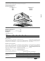
OPERATING LIMITS
The fan coil is a room air treatment terminal unit for mainly summer operation.
Install the unit on the suspended ceiling.
AVAILABLE VERSIONS AND SIZES
VEC fan coils are available in:
4 sizes with a 3-row coil compulsory accessory
VEC 20 VEC 20 GL
VEC 30 VEC 30 GL
VEC 40 VEC 40 GL
VEC 50 VEC 40 GL
DESCRIPTION OF THE UNIT
In order to prevent air stratification
in the room, and therefore to achieve
improved mixing, it is obligatory not
to supply the fan coil with water at a
temperature over 50°C.
The use of water at high temperatures
could cause squeaking due to the
different thermal expansions of the
elements (plastic and metal), this does
not however cause damage to the unit if
the maximum operating temperature is
not exceeded.
Maximum water input temperature ........................... 50°C
Maximum operating pressure ..................................... 8 bar
Operating voltage ..............................230V(±10%) ~ 50Hz
Room temperature .................................................. 0-40°C
Air humidity .....................................................<85% U.R.
Output limits (3-row coil):
MOD. VEC 20 30 40 50
Minimum output [l/h] 100 100 150 150
Maximum output [l/h] 750 750 1100 1100
Minimum average water temperature
Water temperature
VEC 20
VEC 20 GL

English
12
IVECLJ 1009 - 5074550_04
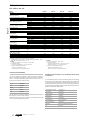
TECHNICAL DATA
Performance values refer to the following conditions:
Sound pressure measured in
semi-reverberating chamber, 85m
3
,
and with reverberation time Tr = 0.5s.
Cooling:
- room air temperature 27°C D.B., 19°C W.B.;
• maximum speed:
- water inlet temperature 7°C; 't water 5°C.
• medium and minimum speed:
- water inlet temperature 7°C;
- water flow rate as at maximum speed.
Heating:
room air temperature 20°C D.B.;
• maximum speed:
- water inlet temperature 50°C; 't water 10°C.
- water flow rate as for cooling operation.
• medium and minimum speed:
- water inlet temperature 50°C;
- water flow rate as at maximum speed.
Mod.
Heating
W (max.)
Heating capacity W (med.)
W (min.)
Electric heater heating capacity W
Cooling
W (max.)
Total cooling capacity W (med.)
W (min.)
W (max.)
Sensible cooling capacity W (med.)
W (min.)
Water flow rate l/h
Water pressure drops kPa
m
3
/h (max.)
Air flow rate
m
3
/h (med.)
m
3
/h (min.)
Number of fans
dB (A) (max.)
Sound power dB (A) (med.)
dB (A) (min.)
dB (A) (max.)
Sound power dB (A) (med.)
dB (A) (min.)
Water content l
Max. motor power W
Max. input current A
Max. motor power
W
with electric heater
Input current
A
with electric heater
3R coil connections ø
1R coil connections ø
Power supply
VEC with a 3-row coil
VEC 20 VEC 30 VEC 40 VEC 50
1835 2770 3745 4285
1505 2340 3105 3785
1105 1950 2505 2840
950 1300 1650 1950
1320 1950 2985 3610
1085 1645 2470 3170
805 1370 1985 2350
1085 1535 2410 2595
885 1285 1980 2275
640 1055 1580 1680
227 335 514 621
4,6 13,3 11,3 14,8
247 383 511 613
194 309 406 529
130 241 306 371
1 2 2 2
39,5 36,5 40,0 44,5
33,5 31,5 34,5 41,5
26,5 26,5 29,5 34,5
48,0 45,0 48,5 53,0
42,0 40,0 43,0 50,0
35,0 35,0 38,0 43,0
0,79 1,11 1,48 1,48
25 44 57 67
0,12 0,21 0,28 0,35
975 1344 1707 2017
4,25 5,86 7,45 8,83
1/2" 1/2" 3/4" 3/4"
1/2" 1/2" 1/2" 1/2"
230V ~ 50Hz
OPERATING ENVIRONMENT
dŚĞ ƵŶŝƚƐ ĂƌĞ ĚĞƐŝŐŶĞĚ ĨŽƌ ŝŶƐƚĂůůĂƟŽŶ ŝŶ ĐůŽƐĞĚ ĞŶǀŝƌŽŶŵĞŶƚƐ ŝŶ ĐŽŶĚŝƟŽŶƐ ŽĨ
͚ƵƌďĂŶ͕͛ŶŽŶͲŵĂƌŝŶĞĂƚŵŽƐƉŚĞƌĞǁŝƚŚŶŽŶͲĐŽƌƌŽƐŝǀĞĂŶĚŶŽŶͲĚƵƐƚLJĐŚĂƌĂĐƚĞƌŝƐƟĐƐ͘
hŶĚĞƌ ŶŽ ĐŝƌĐƵŵƐƚĂŶĐĞƐ ƚŚĞ ĨŽůůŽǁŝŶŐ ĐŽŶĐĞŶƚƌĂƟŽŶƐ ŽĨ ƉŽůůƵƚĂŶƚƐ ŝŶ ƚŚĞ Ăŝƌ͕ ŝŶ
ǁŚŝĐŚƚŚĞƵŶŝƚŵƵƐƚŽƉĞƌĂƚĞ͕ƐŚĂůůďĞĞdžĐĞĞĚĞĚ͗
SO
2
<0,02 ppm
H
2
S <0,02 ppm
NO,NO
2
<1 ppm
NH
3
<6 ppm
N
2
O <0,25 ppm
dŚĞ ƵŶŝƚ ƐŚŽƵůĚ ŶŽƚ ďĞ ŝŶƐƚĂůůĞĚ ŝŶ ůŽĐĂƟŽŶƐ ĐŚĂƌĂĐƚĞƌŝnjĞĚ ďLJ ƚŚĞƉƌĞƐĞŶĐĞŽĨ
ŇĂŵŵĂďůĞŐĂƐĞƐŽƌĂĐŝĚŝĐŽƌĂůŬĂůŝŶĞƐƵďƐƚĂŶĐĞƐ͘
KƚŚĞƌǁŝƐĞ ƚŚĞ ĐŽŝůƐ ĂŶĚ ƚŚĞ ŝŶƚĞƌŶĂů ĐŽŵƉŽŶĞŶƚƐ ŽĨ ƚŚĞ ĞƋƵŝƉŵĞŶƚ ĐŽƵůĚ ƐƵīĞƌ
ƐĞƌŝŽƵƐĂŶĚŝƌƌĞƉĂƌĂďůĞĚĂŵĂŐĞĨƌŽŵĐŽƌƌŽƐŝŽŶ͘
WARNINGS FOR THE QUALITY OF THE WATER CIRCULATING
IN THE COILS
/ƚŝƐƌĞĐŽŵŵĞŶĚĞĚƚŽƉĞƌĨŽƌŵĂŶĂŶĂůLJƐŝƐŽĨƚŚĞǁĂƚĞƌĐŝƌĐƵůĂƟŶŐŝŶƚŚĞĐŽŝůĨŽĐƵƐŝŶŐ
ŽŶƚŚĞƌĞƐĞĂƌĐŚŽĨƚŚĞƉŽƐƐŝďůĞƉƌĞƐĞŶĐĞŽĨďĂĐƚĞƌŝĂ;ĚĞƚĞĐƟŽŶŽĨŝƌŽŶďĂĐƚĞƌŝĂĂŶĚ
ŵŝĐƌŽͲŽƌŐĂŶŝƐŵƐƚŚĂƚĐĂŶƉƌŽĚƵĐĞ,Ϯ^ŽƌĐŚĞŵŝĐĂůůLJƌĞĚƵĐĞƐƵůƉŚĂƚĞƐͿĂŶĚŽŶƚŚĞ
ĐŚĞŵŝĐĂůĐŽŵƉŽƐŝƟŽŶŽĨƚŚĞǁĂƚĞƌ͕ƚŽƉƌĞǀĞŶƚĐŽƌƌŽƐŝŽŶĂŶĚĨŽƵůŝŶŐŝŶƐŝĚĞƚŚĞƚƵďĞƐ͘
dŚĞǁĂƚĞƌĐŝƌĐƵŝƚŵƵƐƚďĞƐƵƉƉůŝĞĚĂŶĚƌĞƉůĞŶŝƐŚĞĚǁŝƚŚƚƌĞĂƚĞĚǁĂƚĞƌƚŚĂƚĚŽĞƐŶŽƚ
ĞdžĐĞĞĚƚŚĞƚŚƌĞƐŚŽůĚůĞǀĞůƐŝŶĚŝĐĂƚĞĚďĞůŽǁ͘
Total hardness in mmol/l l < mmoll/l < 1,5
Chlorides [CL
-
] < 10 mg/litre
Sulphates [SO
4
2-
] < 30 mg/litre
Nitrates [NO
3
-
] = 0 mg/litre
ŝƐƐŽůǀĞĚŝƌŽŶ < 0,5 mg/litre
ŝƐƐŽůǀĞĚŽdžLJŐĞŶ 4 < [O
2
] < 9 mg/litre
ĂƌďŽŶĚŝŽdžŝĚĞK
2
] < 30 mg/litre
ZĞƐŝƐƟǀŝƚLJ ϮϬKŚŵͼŵфZĞƐŝƐƟǀŝƚLJфϱϬKŚŵͼŵ
pH 6,9 < pH < 8

English
13
IVECLJ 1009 - 5074550_04
The unit must be connected directly
to an electrical outlet or to an
independent circuit.
To protect the unit against short circu-
its, fit an omnipolar thermal-magnetic
trip 2A 250V (IG) to the power line
with a minimum contact opening
distance of 3mm.
CHARACTERISTICS OF THE
CONNECTION CABLES
Use H05V-K or N07V-K type cables
with 300/500V with insulation, piped
or ducted.
All the cables must be piped or ducted
until they are inside the fan coil.
The cables coming out of the pipe or
duct must not be subject to stretching
or twisting. They must be protected from
external agents.
Stranded wires can only be used with
terminating sleeves. Make sure that the
strands of the wires are inserted pro-
perly.
Wiring diagrams are constantly upda-
ted. It is therefore compulsory to refer
to the ones supplied with the unit.
The control panel may not be fitted on
a metal wall unless this is permanently
connected to an earthed outlet.
The control panels consist simply of
electric circuits connected at the mains
voltage of 230V; all the inputs for the
probes and controls must therefore be
correspondingly insulated for this vol-
tage.
Multifunctional electronic thermostats
are provided ready for operation in the
standard configuration but allow the
installer to adjust them to the specific
necessities of the system by modifying
the internal dip-switch configuration.
The functions that can be customised might
vary from model to model, for this reason it
is advisable to consult the relevant manuals.
WARNING:check whether the instal-
lation has been carried out correct-
ly. FOLLOW THE CHECKING PROCE-
DURES indicated in the control panel
manuals.
INSTALLATION
INSTALLING THE UNIT
ELECTRICAL WIRINGS
WARNING: before carrying out any
intervention, check the power supply is
disconnected.
WARNING:before carrying out any
work, put the proper individual
protection equipment on.
WARNING: the appliance must be fitted
according to the national regulations on
process plant engineering.
WARNING: electrical wirings,
installation of the fan coils and relevant
accessories should be performed by
a technician who has the necessary
technical and professional expertise
to install, modify, extend and maintain
systems, and who is able to check the
systems for the purposes of safety and
correct operation.
WARNING: install a device, main
switch or plug which allows to
completely cut off the power supply
from the unit.
Instructions which are essential for the
proper installation of the equipment are
given here.
The completion of all the operations
in accordance with the specific
requirements is however left to the
experience of the installation engineer.
Do not install units in rooms where
there are inflammable gases or acid
or alkaline substances that could
irretrievably damage the aluminium-
copper heat exchanger or the internal
plastic parts.
Do not install the unit in workshops or
kitchens where the oil vapours mixed
with the treated air can be deposited
on the exchange coils, reducing their
performance, or on the parts inside the
unit, damaging the plastic parts.
Choose a position at the centre of the
room whenever possible; adjusting the
air output allows air to be distributed
optimally within the room. Do not
install at a height above three metres.
- Choose the place where to install
the unit according to the layout of
the room, the number of units to be
installed and any limitations imposed
by the architecture. Check that the
chosen place facilitates installing and
servicing the unit.
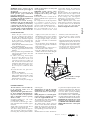
- Install four M8 threaded rods into the
ceiling to hold the frame.
VEC allows 2 installation options thanks
to the grill prepared to be fixed in two
positions:
A) for suspended ceiling installation with
reduced space that requires units with
small dimensions.
B) allows (increasing total height)
to increase the difference in level
between condensate drain and
suspended ceiling by a further 30
mm, to make the realisation of the
condensate drain ducting even easier,
in order to prevent, in most cases,
the necessity for a condensate drain
pump.
To install the VEC unit, proceed as
follows:
- open the cardboard box
- if necessary, mount any accessory
before installing the unit on the ceiling
WARNING: consult the relevant
manuals of the accessories
- lift the unit carefully and, keeping it
slightly inclined, attach it to the 4
threaded bars using 8 nuts, 4 of which
are self-locking. Operate the nuts
to adjust height; finally, check that
the unit is installed in a horizontal
position
- lay the hydraulic pipes through the
suspended ceiling to the attachment
plate on the unit
- make the hydraulic connections as
described in the relative chapter
- bring the condensate discharge pipe
so that it matches the relative fitting on
the condensate discharge device
- drain the system via the drain valve
- bring the power supply and the
control cables close to the electrical
box
- adjust the position of the unit from the
support bracket by means of the nuts
so that the unit is level and the frame
rests slightly on the suspended ceiling
- start the fan coil unit and carry out
an operation test; the functions are
described in the User Manual
Do not install at a height
above three metres.

39
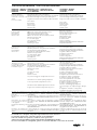
PROBLEMA • PROBLEM
PROBLEME
•
PROBLEM
PROBLEMA
Poca aria in uscita.
Feeble air discharge.
Il y a peu d’air en sortie.
Schwacher Luftstrom am
Austritt.
Poco aire en salida.
Non fa caldo.
It does not heat.
Pas de chaleur.
Keine Heizung.
No hace calor.
Non fa freddo.
It does not cool.
Pas de froid.
Keine Kühlung.
No hace frío.
Il ventilatore non gira.
The fan does not turn.
Le ventilateur ne tourne pas.
Ventilator Arbeitet nicht.
El ventilador no gira.
Fenomeni di condensazione
sulla struttura esterna dell’ap-
parecchio.
Condensation on the unit
cabinet.
Phénomènes de condensa-
tion sur la structure exterieu-
re de l’appareil.
Kondenswasserbildung am
Gerät.
Fenómenos de condensación
en la estructura externa del
aparato.
PROBABILE CAUSA • PROBABLE CAUSE
CAUSE PROBABLE • MÖGLICHE URSACHE
CAUSA PROBABLE
Errata impostazione della velocità sul pannello comandi.
Wrong speed setting on the control panel.
Mauvaise préselection de la vitesse sur le panneau de commandes.
Falsche Geschwindigkeitseinstel lung am Bedien paneel.
Programación errada de la velocidad en el tablero de mandos.
Filtro intasato.
Blocked filter.
Filtre encrassé.
Filter verstopft.
Filtro atascado.
Ostruzione del flusso d’aria (entrata e/o uscita).
Obstruction of the air flow (inlet and/or outlet).
Obstruction du flux d’air (entrée/sortie).
Luftstrom behindert (Eintritt bzw. Austritt).
Obstrucción del chorro del aire (entrada y/o salida).
Mancanza di acqua calda.
Poor hot water supply.
Il n’y a pas d’eau chaude.
Kein Warmwasser.
Falta de agua caliente.
Impostazione errata del pannello comandi.
Wrong setting on control panel.
Mauvaise présélection sur le panneau de commandes.
Falsche Einstellung am Bedien paneel.
Programación errada del tablero de mandos.
Mancanza di acqua fredda.
Poor chilled water supply.
Il n’y a pas d’eau froide.
Kein Kaltwasser.
Falta de agua fría.
Impostazione errata del pannello comandi.
Wrong setting on control panel.
Mauvaise présélection sur le panneau de commandes.
Falsche Einstellung am Bedien paneel.
Programación errada del tablero de mandos.
Mancanza di corrente.
No current.
l n’y a pas de courant.
Kein Strom.
Falta de corriente.
L’acqua non ha raggiunto la temperatura d’esercizio.
The water has not reached operating temperature.
L'eau n'a pas atteint la température de service.
Das Wasser hat die Betriebstemperatur nicht erreicht.
El agua no ha alcanzado la temperatura de ejercicio.
Sono state raggiunte le condizioni limite di temperatura
e umidità descritte in “MINIMA TEMPERATURA MEDIA
DELL’ACQUA”.
The limit conditions of temperature and humidity indicated in
“MINIMUM AVERAGE WATER TEMPERATURE” have been
reached.
On a atteint les conditions limite de température et d’humi-
dité indiquées dans “TEMPERATURE MINIMALE MOYENNE
DE L'EAU”.
Erreichen der maximalen Temperatur- und Feuchtigkeitswerte
(siehe Abschnitt “DURCHSCHNITTLICHE MINDEST -
WASSERTEMPERATUR”).
Se han alcanzado las condiciones límites de temperatura
y humedad descritas en “MÍNIMA TEMPERATURA MEDIA
DEL AGUA".
SOLUZIONE • REMEDY
SOLUTION • ABHILFE
SOLUCIÓN
Scegliere la velocità corretta sul pannello comandi.
Select the speed on the control panel.
Choisir la vitesse sur la panneau de commandes.
Die Geschwindigkeit am Bedien paneel wählen.
Elegir la velocidad correcta en el tablero de mandos.
Pulire il filtro.
Clean the filter.
Nettoyer le filtre.
Filter reinigen.
Limpiar el filtro.
Rimuovere l’ostruzione.
Remove the obstruction.
Enlever l’objet faisant obstruction.
Verstopfung beseitigen.
Quitar la obstrucción.
Controllare la caldaia.
Control the boiler.
Verifier la chaudière.
Kaltwasserseitigen Wärmeaus tau scher kontrollieren.
Comprobar el calentador.
Impostare il pannello comandi.
See control panel settings.
Présélectionner au panneau de commandes.
Richtige Einstellung am Bedien paneel vornehmen.
Programar el tablero de mandos.
Controllare il refrigeratore.
Control the chiller.
Vérifier le réfrigerateur.
Kaltwasserseitigen Wärmeaus tau scher kontrollieren.
Comprobar el refrigerador.
Impostare il pannello comandi.
See control panel settings.
Présélectionner au panneau de commandes.
Richtige Einstellung am Bedien paneel vornehmen.
Programar el tablero de mandos.
Controllare la presenza di tensione elettrica.
Control the power supply.
Contrôler l’alimentation électrique.
Kontrollieren, ob Spannung anliegt.
Comprobar la presencia de tensión eléctrica.
Controllare la caldaia o il refrigeratore.
Controllare il settaggio del termostato.
Please check up the boiler or the chiller.
Check up the thermostat settings.
Contrôler la chaudière ou le refroidisseur.
Contrôler le réglage du thermostat.
Das Heiz- oder Kühlaggregat überprüfen.
Die Einstellungen des Temperaturreglers überprü-
fen.
Comprobar el calentador o el refrigerador.
Comprobar la programación del termostato.
Innalzare la temperatura dell’acqua oltre i limi-
ti minimi descritti in “MINIMA TEMPERATURA
MEDIA DELL’ACQUA”.
Increase the water temperature beyond the mini-
mum limits indicated in “MINIMUM AVERAGE
WATER TEMPERATURE”.
Elever la température de l’eau audelà des limites
minimales indiquées dans “TEMPERATURE MINI-
MALE MOYENNE DE L'EAU”.
Wassertemperatur über die um Abschnitt “DURCH-
SCHNITTLICHE MINDEST - WASSERTEMPERATUR”
angegebenen min. Werte erhöhen.
Aumentar la temperatura del agua por encima de
los límites descritos en “Mínima temperatura media
del agua”.
Per anomalie non contemplate, interpellare tempestivamente il Servizio Assistenza.
For anomalies don’t hesitate, contact the aftersales service immediately.
Pour toute anomalie non répertoriée, consulter le service après-vente.
Sich bei hier nicht aufgeführten Störungen umgehend an den Kundendienst wenden.
En el caso de anomalías no contempladas, ponerse en contacto de inmediato con el Servicio de Asistencia.
SOLUZIONE DEI PROBLEMI • SOLUTION DES PROBLEMES
-
 1
1
-
 2
2
-
 3
3
-
 4
4
-
 5
5
-
 6
6


dans d''autres langues
- English: Aermec VEC series Installation guide
Documents connexes
Autres documents
-
Hoover HHSBSO 6174B Manuel utilisateur
-
Gaggenau DF 241 Manuel utilisateur
-
Zephyr PRB15C01AG Manuel utilisateur
-
-
-
-
Zephyr PRW24C02ABSG Manuel utilisateur
-
CONTINENTAL EDISON CECC259AP Manuel utilisateur
-
Lexmark MarkNet N8352 Manuel utilisateur