Kichler Lighting 330174MWH Guide d'installation
- Catégorie
- Ventilateurs ménagers
- Taper
- Guide d'installation

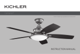
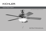
INSTRUCTION MANUAL
Product images may vary slightly from actual product.
42"/52" Starkk
™
LED

2 | KICHLER.COM

TABLE OF CONTENTS
SAFETY RULES ..................................................................4
TOOLS REQUIRED ............................................................5
PACKAGE CONTENTS ................................................... 6
MOUNTING OPTIONS .................................................... 6
HANGING THE FAN ..........................................................7
INSTALLATION OF SAFETY SUPPORT ................... 9
ELECTRICAL CONNECTIONS ..................................10
FINISHING THE INSTALLATION................................ 11
ATTACHING THE FAN BLADES .................................12
INSTALLING THE Light PLATE ..................................12
INSTALLING THE LIGHT KIT ....................................... 13
INSTALLING THE GLASS SHADE .............................14
OPERATING INSTRUCTIONS .....................................15
TROUBLESHOOTING....................................................16
FCC INFORMATION ...................................................... 18
42"/52" Starkk
™
LED | 3

4 | KICHLER.COM
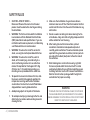
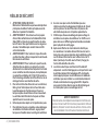
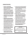
1. CAUTION – RISK OF SHOCK –
Disconnect Power at the main circuit breaker
panel or main fusebox before starting and during
the installation.
2. WARNING: This fixture is intended for installation
in accordance with the National Electrical Code
(NEC) and all local code specifications. If you are
not familiar with code requirements, installation by
a certified electrician is recommended.
3. WARNING: To reduce the risk of fire or electric
shock, use only the control provided with the fan.
4. WARNING: To reduce the risk of fire, electric
shock, or Personal Injury, mount directly to a
structural framing member or to an outlet box
marked “Acceptable for Fan Support of 15.9kg
(35 lbs) or less”. For outlet box mounting, use
mounting screws provided with the outlet box.
5. To operate the reverse function on this fan, slide
the reverse switch to the opposite position. Do
not operate reversing switch while fan blades
are in motion. Fan must be turned o and blades
stopped before reversing blade direction.
6. Avoid placing objects in the path of the blades.
7. To avoid personal injury or damage to the fan and
other items, be cautious when working around or
cleaning the fan.
8. Make sure the installation site you choose allows a
minimum clearance of 7 feet from the blades to the floor
and at least 30 inches from the ends of the blades to any
obstruction.
9. Do not use water or detergents when cleaning the fan
or fan blades. A dry dust cloth or lightly dampened cloth
will be suitable for most cleaning.
10. After making the electrical connections, spliced
conductors should be turned upward and pushed
carefully up into outlet box. The wires should be spread
apart with the ground wire and white (common) wire to
one side with the black (load) wire to the other side of
the outlet box.
11. Electrical diagrams are for reference only. Light kits
that are not packed with the fan must be ETL Listed
and marked suitable for use with the model fan you are
installing. Switches must be ETL General Use Switches.
Refer to the Instructions packaged with the light kits
and switches for proper assembly.
WARNING
TO REDUCE THE RISK OF PERSONAL INJURY, DO NOT BEND
THE BLADE BRACKETS (ALSO REFERRED TO AS FLANGES)
DURING ASSEMBLY OR AFTER INSTALLATION. DO NOT INSERT
OBJECTS IN THE PATH OF THE BLADES.
SAFETY RULES

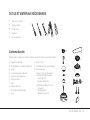
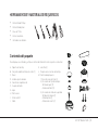
TOOLS AND MATERIALS REQUIRED
Package contents
• Phillips Screwdriver
• Blade Screwdriver
• 11 mm Wrench
• Step Ladder
• Wire Cutters
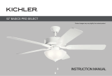
Unpack your fan and check the contents. You should have the following items:
A. Mounting Bracket
B. Ball / Downrod Assembly (1)
C. Canopy
D. Canopy Trim Ring
E. Coupling Cover
F. Motor Body
G. Blade
H. Light Plate
I. LED Light Kit
J. Glass
K. Fob (2)
L. Mounting Hardware Package
M. Package Contents:
1.) Mounting Connectors (3)
2.) Blade Attachment Hardware:
Blade Screw (15)
Fiber Washer (15)
3.) Safety Cable Hardware:
Wood Screw (1)
Flat Washer (1)
Spring Washer (1)
A
B
C
D
E
F
G
H
I
J
M
K
L
42"/52" Starkk
™
LED | 5

6 | KICHLER.COM
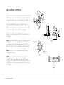
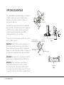
MOUNTING OPTIONS
If there isn’t an existing UL (cUL for Canadian Installation) listed
mounting box, then read the following instructions. Disconnect
the power by removing fuses or turning o circuit breakers.
Secure the outlet box directly to the building structure. Use
appropriate fasteners and building materials. The outlet box
and its support must be able to fully support the full weight of
the fan (up to 50 lbs). Do not use plastic outlet boxes.
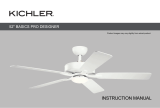
Figures 1, 2 and 3 are examples of dierent ways to mount the
outlet box.
NOTE: If you are installing the ceiling fan on a sloped (vaulted)
ceiling, you may need a longer downrod to maintain proper
clearance between the tip of the blade and the ceiling. A
minimum clearance of 12" is suggested for optimal operation.
NOTE: You must use 12" or longer downrod for 30° slope
(max angle 30°). (Fig. 3)
NOTE: Depending on the location you have selected for
installation, you may need to purchase and install a “Joist
Hanger” for the support of the outlet box. Make sure the joist
hanger you purchase has been designed for use with ceiling
fans. (Fig. 4)
Fig. 1
Outlet box
Outlet box
Fig. 2
Fig. 3
Fig. 4
Outlet box
Recessed
outlet box ceiling
mounting
plane
Provide strong
support
ANGLED CEILING
MAXIMUM 30° ANGLE

Fig. 5
Fig. 6
Fig. 7
Outlet Box
Mounting
Bracket
Flat Washer
Screw
Mounting
Bracket
Shoulder
Downrod
Set Screw
Hanger Ball
Cross Pin
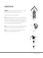
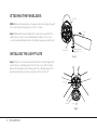
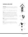
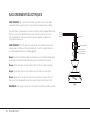
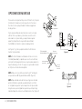
HANGING THE FAN
REMEMBER to turn o the power before you begin installation. This is necessary for
your safety and also the proper programming of the control system.
To properly install your ceiling fan, follow the steps below.
Step 1. Before attaching fan to outlet box (not included), ensure the outlet box is securely
fastened to at least two points to a structural ceiling member (a loose box will cause the
fan to wobble). Pass the 120 volt supply wires from the ceiling outlet box through the
center of the ceiling mounting bracket. Install mounting bracket to outlet box in ceiling
using the screws and washers included with the outlet box. (Fig. 5)
Step 2. Remove one of the two shoulder screws in the mounting bracket and save it for
later use. Loosen the second shoulder screw without fully removing it. (Fig. 6)
Step 3. Remove the hanger ball from downrod assembly by loosening set screws,
removing the cross pin, and twisting ball o the rod. ( Fig. 7)
42"/52" Starkk
™
LED | 7

8 | KICHLER.COM
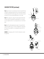
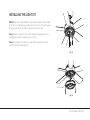
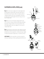
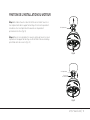
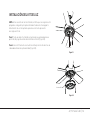
HANGING THE FAN (continued)
Step 4. Loosen the two set screws and remove the clip and cross pin from the top
coupling of the motor body.Carefully feed the fan wires up through the downrod.
Thread the downrod onto the motor coupling until the cross pin holes are aligned.
Next, replace the cross pin and clip, and tighten both set screws. (Fig.8)
Step 5. Slip the coupling cover, canopy trim ring and canopy onto the downrod.
Carefully reinstall the hanger ball onto the downrod. Make sure the cross pin is
in the correct position and the set screws are tight and the wires are not twisted.
(Fig.9)
Step 6. Now lift the motor body into position and place the hanger ball into the
hanger bracket. Rotate until the “Check Tab” has dropped into the “Registration
Slot” and seats firmly. (Fig.10) The entire motor body should not rotate if this is
done correctly.
WARNING: Failure to properly seat the “Check Tab” can damage the ceiling fan
during operation.
Cross Pin
Clip
Clip
Set Screw
Cross Pin
Set Screw
Motor Body
Fig. 8
Fig. 9
Fig. 10
Canopy
Hanger Ball
Canopy Trim Ring
Coupling Cover
Motor Body
Mounting
Bracket
Hanger
Ball
Registration Slot
Check Tab

Flat Washer
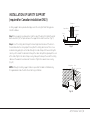
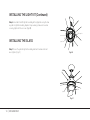
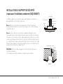
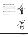
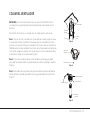
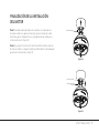
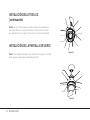
INSTALLATION OF SAFETY SUPPORT
(required for Canadian installation ONLY)
A safety support cable is provided to help prevent the ceiling fan from faIling, please
install it as follows.
Step 1. Drive a wood screw and washers into the side of the brace that holds the outlet
box. Leave 3mm (1/8") of space between the support brace and the washer. (Fig. 11)
Step 2. Insert the safety cable through the mounting bracket and one of the holes in
the outlet box into the ceiling. Adjust the length of the safety cable to reach the screw
and washers by pulling the extra cable through the cable clamp until the overall length is
correct, put the end of the cable back through the cable clamp, forming a loop at the end
of the cable. Tighten the cable clamp securely. Now, put the loop in the end of the safety
cable over the wood screw and under the washer. Tighten the wood screw securely.
(Fig. 12)
NOTE: Although the safety support cable is required for Canadian installations only.
It’s a good idea to make the attachment with any installation.
Wood Screw
Spring Washer
Outlet Box
Ceiling
Support Brace
Safety Cable
Bolt
Wood Screw
Fig. 12
Fig. 11
42"/52" Starkk
™
LED | 9

10 | KICHLER.COM
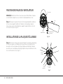
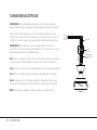
ELECTRICAL CONNECTIONS
WARNING: To avoid possible electrical shock, be sure you have turned o the power at
the main circuit panel before wiring.
Follow the steps below to connect the fan to your household wiring. Use the wire
connectors supplied with your fan. Secure the connector with electrical tape. Make sure
there are no loose wire stands or connections.
WARNING: If your house wires are dierent colors than referenced in this manual, stop
immediately. A professional electrician is recommended to determine proper wiring.
Step 1. Connect the fan supply (black) wire and light supply (blue) wire to the black
household supply wire as shown in Figure 13.
Step 2. Connect the neutral fan (white) wire to the neutral household (white) wire.
Step 3. Connect the fan ground wire (green) to the household ground wire.
Step 4. After connecting the wires, spread them apart so that the green and white wires
are on one side of the outlet box and the black wires is on the other side.
NOTE: Carefully tuck the wire connections up into the outlet box.
Vac 120V
Supply Wire
Green ground
Wiring box
Ground to
mounting bracket
and downrod
BLACK
WHITE
BLACK
WHITE
GREEN
BLUE
Fig. 13

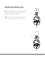
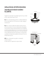
FINISHING THE MOTOR INSTALLATION
Step 1. Assemble canopy by rotating key slot in canopy over shoulder screw in
mounting bracket. Tighten shoulder screw. Fully assemble and tighten second
shoulder screw that was previously removed. (Fig. 14)
Step 2. Securely attach and tighten the canopy hole cover over the shoulder
screws in the mounting bracket utilizing the keyslot twist-lock feature. (Fig. 15)
Shoulder Screw
Shoulder Screw
Canopy Hole Cover
Fig. 14
Fig. 15
42"/52" Starkk
™
LED | 11

12 | KICHLER.COM
ATTACHING THE FAN BLADES
NOTE: Before continuing, make sure the power is disconnected by turning o
the circuit breaker of removing the fuse at the circuit box.
Step 1. Slide blades through the blade slots in motor housing and attach to
motor brackets using the screws and blade plates. Make sure the screws
securing the blade to blade bracket are tight and are properly seated. (Fig. 16)
INSTALLING THE LIGHT PLATE
Step 1. Remove the screw marked with a dot label on the mounting plate and
save for later use, and slightly loosen the other two screws. Attach the light
plate to mounting plate using the two key slots in the light plate. Replace the
previously removed screw and securely tighten all 3 screws. (Fig. 17)
Blade Slot
Blade
Blade Washer
Blade Screw
Blade Bracket
Mounting
Plate
Light Plate
Screw
Fig. 16
Fig. 17

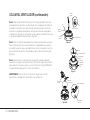
INSTALLING THE LIGHT KIT
NOTE: Before continuing installation, confirm that the power is still turned o
at the main circuit breaker or by removing the correct fuse. Turning the power
o using a wall switch is not sucient to prevent electrical shock.
Step 1. Remove one of the three screws in light plate and keep for later use,
slightly loosen the other remaining screws. (Fig. 18)
Step 2. Securely attach the 9-pin connector to the wiring harness socket
within the motor assembly (Fig. 19)
Light Plate
LED Light Kit
Fig. 18
Fig. 19
42"/52" Starkk
™
LED | 13

14 | KICHLER.COM
INSTALLING THE LIGHT KIT (Continued)
Step 3. Assemble the LED light kit assembly to the light plate using the two
key slots in light kit assembly. Replace the previously removed screw and
securely tighten all three screws. (Fig.20)
INSTALLING THE GLASS
Step 1. Secure the glass to light kit assembly and twist clockwise. Do not
over-tighten. (Fig.21)
LED Light Kit
Light Plate
Light Kit
Glass
Fig. 20
Fig. 21

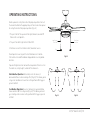
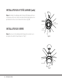
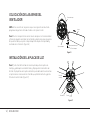
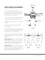
OPERATING INSTRUCTIONS:
Restore power to ceiling fan and test for proper operation. Connect
the decorative fobs to the appropriate pull chains and restore power
to ceiling fan and test for proper operation. (Fig. 22)
1. The pull chain for fan speed control: High, Medium, Low and O.
Pull once for each position.
2. The pull chain kit for light control: ON or OFF.
3. Fan Reverse switch: control direction, forward or reverse.
Do not operate reversing switch while fan blades are in motion.
Fan must be turned o and blades stopped before reversing blade
direction.
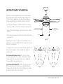
Speed setting for warm or cool weather depends on factors such as
the room size, ceiling height, number of fans and so on.
Warm Weather Operation: Forward (counter clockwise). A
downward airflow creates a cooling eect (Fig. 23). This allows you to
set your air conditioner on a warmer setting without aecting your
general comfort.
Cool Weather Operation: Reverse (clockwise). An upward airflow
moves warm air o the ceiling areas (Fig. 24). This allows you to set
your heating unit on a cooler setting without aecting your general
comfort.
Fob
Light Control
Pull Chain
Fan Control
Pull Chain
Reverse Switch
Fig. 22
Fig. 23 Fig. 24
42"/52" Starkk
™
LED | 15

16 | KICHLER.COM
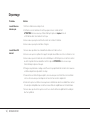
Troubleshooting
Problem Solution
Fan will not start. 1. Check circuit fuses or breakers.
2. Check all electrical connections to ensure proper contact. CAUTION: Make sure the main
power is OFF when checking any electrical connection.
3. Make sure the transmitter batteries are installed properly.
4. Ensure the batteries have a good charge.
Fan sounds noisy. 1. Make sure all motor housing screws are snug.
2. Make sure the screws that attach the fan blade brackets to the motor are tight.
3. Make sure wire nut connections are not rubbing against each other or the interior wall of the
switch housing. CAUTION: Make sure main power is o.
4. Allow a 24-hour “breaking-in” period. Most noise associated with a new fan disappear during
this time.
5. If using an optional light kit, make sure the screws securing the glassware are tight. Make sure
the light bulbs are not touching any other component.
6. Do not connect this fan to wall mounted variable speed control(s). They are not compatible
with ceiling fan motors or remote controls.
7. Make sure the upper canopy is a short distance from the ceiling. It should not touch the ceiling.

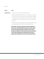
Troubleshooting
Problem Solution
Fan wobble. 1. Check that all blade and blade arm screws are secure.
2. Most fan wobbling problems are caused when blade levels are unequal. Check this level by
selecting a point on the ceiling above the tip of one of the blades. Measure this distance. Rotate
the fan until the next blade is positioned for measurement. Repeat for each blade. The distance
deviation should be equal within 1/8".
3. If the blade wobble is still noticeable, interchanging two adjacent (side by side) blades can
redistribute the weight and possibly result in smoother operation.
WARNING: TO REDUCE THE RISK OF PERSONAL INJURY AND TO ENUSRE THE PROPER
OPERATION OF YOUR CEILING FAN. NEVER ATTACH THE BLADE ASSEMBLIES UNTIL THE
CEILING FAN HAS BEEN MOUNTING ON THE CEILING. DO NOT BEND THE BLADE ARMS
WHILE INSTALLING, BALANCING OR CLEANING THE FAN. DO NOT INSERT FOREIGN
OBJECTS BETWEEN ROTATING FAN BLADES.
42"/52" Starkk
™
LED | 17

18 | KICHLER.COM
FCC Information
This device complies with part 15 of the FCC Rules. Operation is subject to the following two conditions:
1) This device may not cause harmful interference, and
2) This device must accept any interference received, including interference that may cause undesired operation.
Note: This equipment has been tested and found to comply with the limits for a Class B digital device, pursuant to part 15 of the
FCC Rules. These limits are designed to provide reasonable protection against harmful interference in a residential installation. This
equipment generates, uses and can radiate radio frequency energy and, if not installed and used in accordance with the instructions,
may cause harmful interference to radio communications. However, there is no guarantee that interference will not occur in a
particular installation. If this equipment does cause harmful interference to radio or television reception, which can be determined by
turning the equipment o and on, the user is encouraged to try to correct the interference by one or more of the following measures:
• Reorient or relocate the receiving antenna.
• Increase the separation between the equipment and receiver.
• Connect the equipment into an outlet on a circuit dierent from that to which the receiver is connected.
• Consult the dealer or an experienced radio/TV technician for help.

KICHLER LIGHTING
7711 EAST PLEASANT VALLEY ROAD
CLEVELAND, OHIO 44131
CUSTOMER SERVICE 866.558.5706
8:00 AM TO 5:00 PM EST, MONDAY - FRIDAY
© Kichler Lighting LLC. All Rights Reserved.

MANUEL D'INSTRUCTIONS
Les images du produit peuvent varier légèrement par rapport au produit réel.
42"/52" Starkk
™
LED
La page est en cours de chargement...
La page est en cours de chargement...
La page est en cours de chargement...
La page est en cours de chargement...
La page est en cours de chargement...
La page est en cours de chargement...
La page est en cours de chargement...
La page est en cours de chargement...
La page est en cours de chargement...
La page est en cours de chargement...
La page est en cours de chargement...
La page est en cours de chargement...
La page est en cours de chargement...
La page est en cours de chargement...
La page est en cours de chargement...
La page est en cours de chargement...
La page est en cours de chargement...
La page est en cours de chargement...
La page est en cours de chargement...
La page est en cours de chargement...
La page est en cours de chargement...
La page est en cours de chargement...
La page est en cours de chargement...
La page est en cours de chargement...
La page est en cours de chargement...
La page est en cours de chargement...
La page est en cours de chargement...
La page est en cours de chargement...
La page est en cours de chargement...
La page est en cours de chargement...
La page est en cours de chargement...
La page est en cours de chargement...
La page est en cours de chargement...
La page est en cours de chargement...
La page est en cours de chargement...
La page est en cours de chargement...
La page est en cours de chargement...
-
 1
1
-
 2
2
-
 3
3
-
 4
4
-
 5
5
-
 6
6
-
 7
7
-
 8
8
-
 9
9
-
 10
10
-
 11
11
-
 12
12
-
 13
13
-
 14
14
-
 15
15
-
 16
16
-
 17
17
-
 18
18
-
 19
19
-
 20
20
-
 21
21
-
 22
22
-
 23
23
-
 24
24
-
 25
25
-
 26
26
-
 27
27
-
 28
28
-
 29
29
-
 30
30
-
 31
31
-
 32
32
-
 33
33
-
 34
34
-
 35
35
-
 36
36
-
 37
37
-
 38
38
-
 39
39
-
 40
40
-
 41
41
-
 42
42
-
 43
43
-
 44
44
-
 45
45
-
 46
46
-
 47
47
-
 48
48
-
 49
49
-
 50
50
-
 51
51
-
 52
52
-
 53
53
-
 54
54
-
 55
55
-
 56
56
-
 57
57


Kichler Lighting 330174MWH Guide d'installation
- Catégorie
- Ventilateurs ménagers
- Taper
- Guide d'installation
dans d''autres langues
Documents connexes
-
 Kichler Lighting 310204WCP Manuel utilisateur
-
 Kichler Lighting 339501AP Manuel utilisateur
-
 Kichler Lighting 300285AVI Manuel utilisateur
-
 Kichler Lighting 300365MWH Manuel utilisateur
-
 Kichler Lighting 300200PN Manuel utilisateur
-
 Kichler Lighting 300270SBK Manuel utilisateur
-
 Kichler Lighting 310360SBK Manuel utilisateur
-
 Kichler Lighting 330017SNB Manuel utilisateur
-
Kichler Lighting 330016SNB Manuel utilisateur
-
 Kichler Lighting 330019SNB Manuel utilisateur


Autres documents
-
Kichler 300317DBK Manuel utilisateur
-
Kichler 300345SBK Manuel utilisateur
-
Progress Lighting P250000-081 Manuel utilisateur
-
-
 PROGRESS LIGHTNING AirPro P2598 Guide d'installation
-
-
Kichler 310130WH Manuel utilisateur
-
Fanimation FP8519BL Le manuel du propriétaire
-
Parrot Uncle A571201CA110V Guide d'installation
-
