Hatco MDW Series Le manuel du propriétaire
- Taper
- Le manuel du propriétaire

© 2014 Hatco Corporation
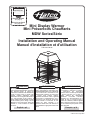
Mini Display Warmer
Mini Présentoirs Chauffants
MDW Series/Série
Installation and Operating Manual
Manuel d'installation et d'utilisation
P/N 07.04.405.00
Register Online!
(see page 2)
S'inscrire en ligne!
(voir page 14)
hatcocorp.com
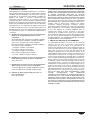
Do not operate this equipment unless you
have read and understood the contents of
this manual! Failure to follow the
instructions contained in this manual may
result in serious injury or death. This
manual contains important safety
information concerning the maintenance,
use, and operation of this product. If
you’re unable to understand the contents
of this manual, please bring it to the
attention of your supervisor. Keep this
manual in a safe location for future
reference.
English = p 2
No opere este equipo al menos que haya
leído y comprendido el contenido de este
manual! Cualquier falla en el seguimiento
de las instrucciones contenidas en este
manual puede resultar en un serio lesión
o muerte. Este manual contiene
importante información sobre seguridad
concerniente al mantenimiento, uso y
operación de este producto. Si usted no
puede entender el contenido de este
manual por favor pregunte a su
supervisor. Almacenar este manual en
una localización segura para la referencia
futura.
Ne pas utiliser cet équipement sans avoir
lu et compris le contenu de ce manuel !
Le non-respect des instructions
contenues dans ce manuel peut entraîner
de graves blessures ou la mort. Ce
manuel contient des informations
importantes concernant l'entretien,
l'utilisation et le fonctionnement de ce
produit. Si vous ne comprenez pas le
contenu de ce manuel, veuillez le signaler
à votre supérieur. Conservez ce manuel
dans un endroit sûr pour pouvoir vous y
référer plus tard.
Français = p 14
WARNING
ADVERTENCIA
AVERTISSEMENT

Form No. MDWM-1214
2
English
IMPORTANT OWNER INFORMATION
INTRODUCTION
Important Owner Information ..............................................2
Introduction...........................................................................2
Important Safety Information...............................................3
Model Description.................................................................4
Model Designation................................................................4
Specifications........................................................................5
Plug Configurations.............................................................5
Electrical Rating Chart ........................................................5
Dimensions .........................................................................5
Installation .............................................................................6
General ...............................................................................6
Reversible Access Door......................................................7
Configurable Access Door ..................................................7
Operation...............................................................................8
General ...............................................................................8
Maintenance ..........................................................................9
General ...............................................................................9
Daily Cleaning.....................................................................9
Display Light Bulb Replacement.......................................10
Troubleshooting Guide.......................................................11
Options and Accessories...................................................12
Limited Warranty.................................................................13
Authorized Parts Distributors............................Back Cover
Record the model number, serial number, voltage, and
purchase date of the unit in the spaces below (specification
label located on the control side of the unit). Please have this
information available when calling Hatco for service assistance.
Model No. ________________________________________
Serial No. ________________________________________
Voltage __________________________________________
Date of Purchase __________________________________
Register your unit!
Completing online warranty registration will prevent delay in
obtaining warranty coverage. Access the Hatco website at
www.hatcocorp.com, select the Parts & Service pull-down
menu, and click on “Warranty Registration”.
Business
Hours: 8:00
AM to 5:00 PM Central Standard Time (CST)
(Summer Hours: June to September—
8:00
AM to 5:00 PM CST Monday–Thursday
8:00
AM to 2:30 PM CST Friday)
Telephone: 800-558-0607; 414-671-6350
e-mail: part[email protected]
Fax: 800-690-2966 (Parts and Service)
414-671-3976 (International)
Additional information can be found by visiting our web site at
www.hatcocorp.com.
24 Hour 7 Day Parts and Service
Assistance available in the United States
and Canada by calling 800-558-0607.
The Hatco Mini Display Warmer is designed to hold prepared
foods for prolonged periods of time while maintaining that “just-
made” quality. Mini Display Warmer cabinets provide the best
environment for products like sandwiches, cookies, pretzels,
muffins, and desserts by regulating the air temperature.
The Mini Display Warmer’s air flow pattern is designed to
maintain consistent cabinet temperature. The heat sources
create a “blanket” effect around the food. The air flow rate
enables the cabinet to rapidly recover temperature after opening
and closing the door. Configurable access doors and magnetic
adjustable shelves make the Hatco Mini Display Warmer perfect
for any food service application.
The Mini Display Warmer is a product of extensive research
and field testing. The materials used were selected for
maximum durability, attractive appearance, and optimum
performance. Every unit is inspected and tested thoroughly prior
to shipment.
This manual provides installation, safety, and operating
information for the Mini Display Warmer. Hatco recommends
all installation, operating, and safety information appearing in
this manual be read prior to installation or operation of a unit.
Safety information that appears in this manual is identified by
the following signal word panels:
WARNING indicates a hazardous situation which, if not
avoided, could result in death or serious injury.
CAUTION indicates a hazardous situation which, if not
avoided, could result in minor or moderate injury.
NOTICE is used to address practices not related to
personal injury.
WARNING
CAUTION
NOTICE
CONTENTS

IMPORTANT SAFETY INFORMATION
Form No. MDWM-1214
3
English
ELECTRIC SHOCK HAZARD:
• Plug unit into a properly grounded electrical receptacle
of the correct voltage, size, and plug configuration. If
plug and receptacle do not match, contact a qualified
electrician to determine and install the proper voltage
and size electrical receptacle.
• Turn OFF power switch, unplug power cord, and allow
unit to cool before performing any cleaning,
adjustments, or maintenance.
• DO NOT submerge or saturate with water. Unit is not
waterproof. Do not operate if unit has been submerged
or saturated with water.
• Unit is not weatherproof. Locate unit indoors where
ambient air temperature is a minimum of 70°F (21°C)
and a maximum of 85°F (29°C).
• Do not steam clean or use excessive water on unit.
• This unit is not “jet-proof” construction. Do not use jet-
clean spray to clean this unit.
• Do not pull unit by power cord.
• Discontinue use if power cord is frayed or worn.
• Do not attempt to repair or replace a damaged power
cord. Cord must be replaced by Hatco, an Authorized
Hatco Service Agent, or a person with similar
qualifications.
• Do not clean unit when it is energized or hot.
• Do not allow liquids to spill into the unit.
• This unit must be serviced by qualified personnel only.
Service by unqualified personnel may lead to electric
shock or burn.
• Use only Genuine Hatco Replacement Parts when
service is required. Failure to use Genuine Hatco
Replacement Parts will void all warranties and may
subject operators of the equipment to hazardous
electrical voltage, resulting in electrical shock or burn.
Genuine Hatco Replacement Parts are specified to
operate safely in the environments in which they are
used. Some aftermarket or generic replacement parts
do not have the characteristics that will allow them to
operate safely in Hatco equipment.
FIRE HAZARD: Locate unit a minimum of 1″ (25 mm) from
combustible walls and materials. If safe distances are not
maintained, discoloration or combustion could occur.
Use only light bulbs that meet or exceed National Sanitation
Foundation (NSF) standards and are specifically designed
for food holding areas. Breakage of light bulbs not specially
coated could result in personal injury and/or food
contamination.
WARNING
Read the following important safety information before using this equipment to avoid serious
injury or death and to avoid damage to equipment or property.
Make sure all operators have been instructed on the safe
and proper use of the unit.
This unit is not intended for use by children or persons
with reduced physical, sensory, or mental capabilities.
Ensure proper supervision of children and keep them away
from the unit.
Hatco Corporation is not responsible for the actual food
product serving temperature. It is the responsibility of the
user to ensure that the food product is held and served at
a safe temperature.
Make sure food product has been heated to the proper
food-safe temperature before placing in unit. Failure to heat
food product properly may result in serious health risks.
This unit is for holding preheated food product only.
This unit has no “user-serviceable” parts. If service is
required on this unit, contact an Authorized Hatco Service
Agent or contact the Hatco Service Department at
800-558-0607 or 414-671-6350; fax 800-690-2966; or
International fax 414-671-3976.
BURN HAZARD: Some exterior surfaces on the unit will get
hot. Use caution when touching these areas.
Locate unit in an area that is convenient for use. The
location should be level and strong enough to support the
weight of the unit and contents.
Transport unit in upright position only. Failure to do so may
result in damage to unit or personal injury.
Do not lay unit on the side with the control panel or damage
to the unit could occur.
Use non-abrasive cleaners and cloths only. Abrasive
cleaners and cloths could scratch finish of unit, marring
its appearance and making it susceptible to soil
accumulation.
Clean unit daily to avoid malfunctions and maintain
sanitary operation.
This unit is intended for commercial use only — NOT for
household use.
WARNING
CAUTION
NOTICE

MODEL DESCRIPTION
Form No. MDWM-1214
4
E
nglish
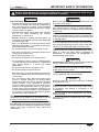
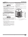
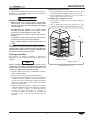
All Models
Mini Display Warmers are powder-coated, painted steel and
feature tempered glass side panels. The access door(s) can be
hinged left or right and mounted on any side of the unit. Two
door units can be configured to allow “pass-through” from either
the side or the back of the unit to the service area. The cabinet
interior top and bottom are made of easy-to-clean stainless
steel. The unit’s dry heat system is suitable for all boxed or
wrapped food products as well as unwrapped muffins,
turnovers, and desserts.
Three magnetically adjustable shelves for horizontal or slanted
displays provide flexibility for a variety of product choices. Shelf
height is also adjustable to accommodate a variety of food
package sizes. The unit has incandescent lighting to heighten
product awareness.
The Hatco Mini Display Warmer keeps food at safe serving
temperatures by circulating hot air throughout the entire cabinet.
Perfect for convenience stores, restaurants, recreational
facilities, theme parks, and anywhere there is limited counter
space.
The Mini Display Warmer is available in several Designer colors.
NOTE: The hood of the Mini Display Warmer is always black.
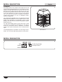
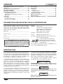
M D W - 1 X
Mini
Warmer
Display
Quantity Of Doors
No Revolving Display
MODEL DESIGNATION
Model MDW-1X

Model Voltage Watts Amps Plug Configuration Shipping Weight
MDX-1X 120 470 3.9 NEMA 5-15P 47 lbs. (21 kg)
MDW-2X 120 470 3.9 NEMA 5-15P 50 lbs. (23 kg)
SPECIFICATIONS
Form No. MDWM-1214
5
English
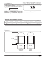
Plug Configuration
Units are supplied from the factory with a 6' (1829 mm) electrical
cord and plug installed.
ELECTRIC SHOCK HAZARD: Plug unit into a properly
grounded electrical receptacle of the correct voltage, size,
and plug configuration. If plug and receptacle do not match,
contact a qualified electrician to determine and install the
proper voltage and size electrical receptacle.
WARNING
Electrical Rating Chart
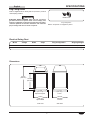
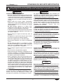
15-3/4″
(400 mm)
Square Base
18-5/16″
(465 mm)
2 Doors
17-1/16″
(432 mm)
1 Door
14-5/8″
(371 mm)
Square Footprint
25-1/2″
(646 mm)
16-1/16″
(407 mm)
Front View Side View
Dimensions
Plug Configuration
NOTE: Receptacle not supplied by Hatco.
NEMA 5-15P

INSTALLATION
Form No. MDWM-1214
6
E
nglish
General
The Mini Display Warmer is shipped with most components
installed and ready for operation. The following installation
instructions must be performed before plugging in and operating
the unit.
ELECTRIC SHOCK HAZARD: Unit is not weatherproof.
Locate unit indoors where ambient air temperature is a
minimum of 70°F (21°C) and a maximum of 85°F (29°C).
FIRE HAZARD: Locate unit a minimum of 1″ (25 mm) from
combustible walls and materials. If safe distances are not
maintained, discoloration or combustion could occur.
Locate unit in an area that is convenient for use. The loca-
tion should be level and strong enough to support the
weight of the unit and contents.
Transport unit in upright position only. Failure to do so may
result in damage to unit or personal injury.
Do not lay unit on the side with the control panel or damage
to the unit could occur.
CAUTION
WARNING
NOTICE
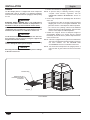
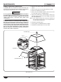
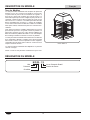
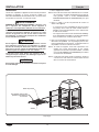
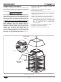
Product Stop
Magnet
Shelves may be
inserted horizontally
or inclined.
Shelf Installation
1. Remove the unit from the shipping carton.
NOTE: To prevent delay in obtaining warranty coverage,
complete online warranty registration. See the
IMPORTANT OWNER INFORMATION section for
details.
2. Remove tape and protective packaging from all surfaces
of the unit.
• The stainless steel floor in all units is protected during
shipping with a sheet of corrugated cardboard. This
protection must be removed prior to cabinet operation.
• The shelves have packing material and cardboard
attached for protection during shipping. This protection
must be removed prior to cabinet operation.
3. Position the magnetic shelves at adequate heights to
accommodate product. The shelves may be inserted
horizontally or inclined with the product stops toward the
service area access.
NOTE: If the unit is equipped with an optional Hood with Backlit
Sign Cutout and the Merchandising Graphic Image has
not been installed, see the OPTIONS AND
ACCESSORIES section for installation instructions.
NOTE: The unit must be transported in the upright position. If
laid on its side, all glass surfaces must be secured with
tape.

INSTALLATION
Form No. MDWM-1214
7
English
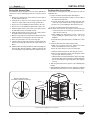
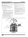
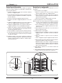
Reversing and Configuring the Access Door
Bottom of Door Bracket
(mounted on left side of opening)
Glass
Bracket
Hinge
Pin
Screw
Hinge
Cap
Outer
Pin
Nylon
Washer
Inner
Pin
Screw
Door
Bracket
Reversible Access Door
Access door(s) may be hinged on either the left or right side for
convenience. Use the following procedure to reverse the access
door.
1. Remove the top hinge pin screw that secures the door to
the door bracket and save.
2. Carefully lift the door off of the bottom hinge pin. Also
remove the nylon washer from the hinge pin and save.
3. Remove the screws holding the door bracket to the unit.
4. Remove the screws holding the glass bracket to the unit.
5. Install the glass bracket on the side of the cabinet where
the door bracket was mounted previously.
6. Install the door bracket on the side of the cabinet where
the glass bracket was mounted previously.
7. Move the hinge cap on the bottom of the door bracket from
what is now the inner hinge pin to the outer hinge pin.
8. Place the nylon washer over the inner hinge pin.
9. Carefully rotate the door 180° and place the door assembly
onto the inner hinge pin (make sure the nylon washer is in
place).
10. Tip/tilt the door assembly towards the cabinet and align the
top of the door with the top hinge. Install the top hinge pin
screw through the hinge and into the door. Tighten securely.
Configurable Access Door
A door can be exchanged with any glass panel to suit the
installation site.
1. Remove the door assembly and the door bracket.
a. Remove the top hinge pin screw that secures the door to
the door bracket and save.
b. Carefully lift the door off of the bottom hinge pin. Also
remove the nylon washer from the hinge pin and save.
c. Remove the screws holding the door bracket to unit.
2. Remove the glass panel and the glass bracket.
NOTE: Make sure to remove only the glass bracket that will be
replaced with the door bracket (the side that the door
hinge will be located on).
a. While holding the glass panel securely, remove the
screws holding the glass bracket to the unit. Keep
hardware.
b. Carefully lift the glass panel off the unit and set in a safe
place.
3. Install the door assembly and the door bracket.
a. Make sure the hinge cap on the bottom of the door
bracket is installed on the outer hinge pin.
b. Place the nylon washer over the inner hinge pin.
c. Attach the door bracket to the unit using the screws.
d. Place the door assembly onto the inner hinge pin (make
sure the nylon washer is in place).
e. Tip/tilt the door assembly towards the cabinet and align
the top of the door with the top hinge. Install the top hinge
pin screw through the hinge and into the door. Tighten
securely.
4. Slide the glass panel into the groove of the installed glass
bracket.
5. While holding the glass panel securely, install the remaining
glass bracket to the unit to secure the glass panel in place.

OPERATION
Form No. MDWM-1214
8
E
nglish
General
Use the following procedure to turn on and operate the Hatco
Mini Display Warmer.
Read all safety messages in the IMPORTANT SAFETY
INFORMATION section before operating this equipment.
Startup
1. Plug unit into an electrical receptacle of the correct voltage,
size, and plug configuration. See the SPECIFICATIONS
section for details.
2. Move the Power I/O (on/off) switch to the I (on) position.
3. Set the Temperature Control to the desired level between
MIN and MAX.
BURN HAZARD: Some exterior surfaces on the unit will get
hot. Use caution when touching these areas.
4. Allow 30 minutes to preheat. Check the interior
thermometer and adjust the Temperature Control if
necessary.
NOTE: Temperature settings may vary depending upon
product make-up and consistency. The interior
thermometer displays temperature inside the cabinet,
not the food product temperature.
Shutdown
1. Move the Power I/O (on/off) switch to the O (off) position.
2. Unplug the power cord and allow the unit to cool before
performing any cleaning or maintenance.
CAUTION
WARNING
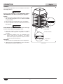
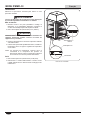
Control Panel
Power I/O Switch
Temperature
Control
Interior
Thermometer

MAINTENANCE
Form No. MDWM-1214
9
English
General
The Hatco Mini Display Warmer is designed for maximum
durability and performance, with minimum maintenance.
ELECTRIC SHOCK HAZARD:
• Turn OFF power switch, unplug power cord, and allow
unit to cool before performing any cleaning,
adjustments, or maintenance.
• DO NOT submerge or saturate with water. Unit is not
waterproof. Do not operate if unit has been submerged
or saturated with water.
• Do not steam clean or use excessive water on unit.
• This unit is not “jet-proof” construction. Do not use jet-
clean spray to clean this unit.
• Do not clean unit when it is energized or hot.
This unit has no “user-serviceable” parts. If service is
required on this unit, contact an Authorized Hatco Service
Agent or contact the Hatco Service Department at
800-558-0607 or 414-671-6350; fax 800-690-2966; or
International fax 414-671-3976.
Daily Cleaning
To preserve the finish of the Mini Display Warmer, perform the
following cleaning procedure daily.
Use non-abrasive cleaners and cloths only. Abrasive
cleaners and cloths could scratch finish of unit, marring its
appearance and making it susceptible to soil accumulation.
1. Turn off the unit, unplug the power cord, and allow the unit
to cool.
2. Remove and wash all food pans.
3. Wipe down all interior and exterior metal surfaces with a
damp cloth. Stubborn stains may be removed with a good
non-abrasive cleaner. Clean hard to reach areas using a
small brush and mild soap.
4. Clean the glass side panels and door panel(s) using ordinary
glass cleaner and a damp, soft cloth or paper towel. The
side panels are removable for detailed cleaning, if
necessary. Refer to the “Removing a Glass Panel”
procedure in this section for removal.
WARNING
NOTICE
Removing a Glass Panel
1. While holding the glass panel securely, remove the screws
holding one of the glass brackets to the unit.
2. Carefully lift the glass panel off the unit and set in a safe
place with the screws.
Installing a Glass Panel
1. Slide the glass panel into the groove of the installed glass
bracket.
2. While holding the glass panel securely, reinstall the
removed glass bracket to the unit.
Glass Panel Removal
Screw
Glass Bracket
Glass Panel

MAINTENANCE
Form No. MDWM-1214
10
E
nglish
Bulb Replacement
Threaded Cap
Hood
Hood Filler Panel
Light Bulb
Display Light Bulb Replacement
The display light is an incandescent bulb that illuminates the
warming area. This bulb has a special coating to guard against
injury and food contamination in the event of breakage.
Use only light bulbs that meet or exceed National Sanitation
Foundation (NSF) standards and are specifically designed
for food holding areas. Breakage of light bulbs not specially
coated could result in personal injury and/or food
contamination.
Use only Genuine Hatco Replacement Parts when service
is required. Failure to use Genuine Hatco Replacement
Parts will void all warranties and may subject operators of
the equipment to hazardous electrical voltage, resulting in
electrical shock or burn. Genuine Hatco Replacement Parts
are specified to operate safely in the environments in which
they are used. Some aftermarket or generic replacement
parts do not have the characteristics that will allow them to
operate safely in Hatco equipment.
WARNING
1. Disconnect the power supply and wait until the unit has
cooled.
2. Unscrew and remove the threaded cap from the hood.
3. Remove the hood from the cabinet.
4. Remove one of the hood filler panels. (Two screws need to
be removed to remove a hood filler panel.)
5. Unscrew the bulb from the unit and replace it with a new,
specially-coated incandescent bulb (display light bulbs
have a threaded base).
NOTE: Hatco shatter-resistant bulbs meet NSF standards for
food holding and display areas. For 120 V applications,
use Hatco P/N 02.30.043.00.
6. Reinstall the hood filler panel.
7. Securely place the hood back onto the cabinet.
8. Reinstall the threaded cap to secure the hood.

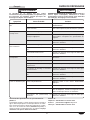
Symptom Probable Cause Corrective Action
Light bulb not working. Light bulb defective. Replace light bulb. Refer to the
MAINTENANCEsection.
Unit not turned on. Move Power I/O (on/off) switch to the I (on)
position.
Unit too hot. Temperature Control set too high. Adjust the Temperature Control to a lower
setting.
Unit connected to incorrect power supply. Verify with qualified personnel that power
supply matches unit specification.
Temperature Control is defective. Contact an Authorized Hatco Service Agent or
Hatco for assistance.
No heat, but light works. Temperature Control set too low. Adjust Temperature Control to a higher
setting.
Heating element(s) not working. Contact an Authorized Hatco Service Agent or
Hatco for assistance.
Temperature Control is defective. Contact an Authorized Hatco Service Agent or
Hatco for assistance.
Unit not hot enough. Unit not allowed enough time to preheat. Allow unit 30 minutes to reach operating
temperature.
Temperature Control set too low. Adjust the Temperature Control to a higher
setting.
Door(s) not closed completely. Make sure all doors are closed completely.
Air circulating fan not working properly. Contact an Authorized Hatco Service Agent or
Hatco for assistance.
Heating element(s) not working. Contact an Authorized Hatco Service Agent or
Hatco for assistance.
Temperature Control is defective. Contact an Authorized Hatco Service Agent or
Hatco for assistance.
Unit not working at all. Unit not plugged in. Plug unit into proper power supply.
Unit not turned on. Move Power I/O (on/off) switch to the I (on)
position.
Circuit breaker tripped. Reset circuit breaker. If circuit breaker
continues to trip, contact an Authorized Hatco
Service Agent or Hatco for assistance.
Power I/O (on/off) switch defective. Contact an Authorized Hatco Service Agent or
Hatco for assistance.
TROUBLESHOOTING GUIDE
Form No. MDWM-1214
11
English
Troubleshooting Questions?
If you continue to have problems resolving an issue, please con-
tact the nearest Authorized Hatco Service Agency or Hatco for
assistance. To locate the nearest Service Agency, log onto the
Hatco website at www.hatcocorp.com and click on
Find Service Agent, or contact the Hatco Parts and Service
Team at:
ELECTRIC SHOCK HAZARD: Turn OFF power switch,
unplug power cord, and allow unit to cool before
performing any cleaning, adjustments, or maintenance.
WARNING
This unit must be serviced by qualified personnel only.
Service by unqualified personnel may lead to electric
shock or burn.
WARNING
Telephone: 800-558-0607 or 414-671-6350
e-mail: p[email protected]
Fax: 800-690-2966 or 414-671-3976

OPTIONS AND ACCESSORIES
Form No. MDWM-1214
12
E
nglish
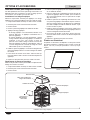
Graphic Panel
Graphic Image
Tab
Threaded Cap
Hood with
Backlit Sign Cutout
Hood
Frame
Hood Filler Panel
Corner
Notch
Hood with Backlit Sign Cutout
Hood with Backlit Sign Cutout
An optional hood with a backlit sign cutout is available for all
models. The hood and sign can be rotated to face any side of
the unit.
Installing a Graphic Image
Use the following procedure to apply a graphic image to the
graphic panel for placement in the hood of the unit.
1. Disconnect the power supply and allow the unit to cool.
2. Unscrew and remove the threaded cap from the hood.
3. Remove the hood.
4. Remove the graphic panel from the hood frame.
5. Apply the graphic image:
• If the graphic image is a decal, peel off the backing
paper from the graphic decal and apply the decal to the
graphic panel.
• If the graphic image is non-adhesive, trim the image to
the shape of the graphic panel leaving no more than an
1/8″ (3 mm) gap between the image and the edge of the
panel. Then, tape the image to the inside face of the
graphic panel. Make sure to tape around the entire edge
of the image so that it does not hang loose.
6. Install the graphic panel with the tabs on the panel resting
in the corner notches of the hood frame.
7. Securely place the hood back onto the cabinet. Make sure
the cutout in the hood is over the graphic panel.
8. Reinstall the threaded cap to secure the hood to the unit.
Relocating the Graphic Panel
Use the following procedure to change the location of the backlit
sign on the unit.
1. Disconnect the power supply and allow the unit to cool.
2. Unscrew and remove the threaded cap from the hood.
3. Remove the hood.
4. Remove the graphic panel from its existing location in the
hood frame.
5. Remove the hood filler panel from the side where the
graphic panel needs to be installed. (Two screws need to
be removed to remove the hood filler panel.)
6. Install the hood filler panel onto the side where the graphic
panel was originally located. Make sure the top lip of the
hood filler panel fits over the edge of the hood frame and
the two screws are installed.
7. Install the graphic panel into the new position with the tabs
on the graphic panel resting in the corner notches of the
hood frame.
8. Securely place the hood back onto the cabinet. Make sure
the cutout in the hood is over the graphic panel.
9. Reinstall the threaded cap to secure the hood.

OPTIONS AND ACCESSORIES
Form No. MDWM-1214
13
English
Aluminum Tray
An aluminum tray is available as an accessory for all models.
The tray is 12-3/8″ (314 mm) W x 12-3/8″ (314 mm) D x 1/4″
(6 mm) H.
Aluminum Tray
1. PRODUCT WARRANTY
Hatco warrants the products that it manufactures (the
“Products”) to be free from defects in materials and
workmanship, under normal use and service, for a period of one
(1) year from the date of purchase when installed and
maintained in accordance with Hatco’s written instructions or 18
months from the date of shipment from Hatco. Buyer must
establish the Product’s purchase date by registering the Product
with Hatco or by other means satisfactory to Hatco in its sole
discretion.
Hatco warrants the following Product components to be free
from defects in materials and workmanship from the date of
purchase (subject to the foregoing conditions) for the period(s)
of time and on the conditions listed below:
a) One (1) Year Parts and Labor PLUS One (1) Additional
Year Parts-Only Warranty:
Conveyor Toaster Elements (metal sheathed)
Drawer Warmer Elements (metal sheathed)
Drawer Warmer Drawer Rollers and Slides
Strip Heater Elements (metal sheathed)
Display Warmer Elements (metal sheathed air heating)
Holding Cabinet Elements (metal sheathed air heating)
Heated Well Elements — HW and HWB Series
(metal sheathed)
b) One (1) Year Parts and Labor PLUS Four (4) Years
Parts-Only Warranty:
3CS and FR Tanks
c) One (1) Year Parts and Labor PLUS Nine (9) Years
Parts-Only Warranty on:
Electric Booster Heater Tanks
Gas Booster Heater Tanks
d) Ninety (90) Day Parts-Only Warranty:
Replacement Parts
THE FOREGOING WARRANTIES ARE EXCLUSIVE AND IN
LIEU OF ANY OTHER WARRANTY, EXPRESSED OR
IMPLIED, INCLUDING BUT NOT LIMITED TO ANY IMPLIED
WARRANTY OF MERCHANTABILITY OR FITNESS FOR A
PARTICULAR PURPOSE OR PATENT OR OTHER
INTELLECTUAL PROPERTY RIGHT INFRINGEMENT.
Without limiting the generality of the foregoing, SUCH
WARRANTIES DO NOT COVER: Coated incandescent light
bulbs, fluorescent lights, heat lamp bulbs, coated halogen light
bulbs, halogen heat lamp bulbs, xenon light bulbs, LED light
tubes, glass components, and fuses; Product failure in booster
tank, fin tube heat exchanger, or other water heating equipment
caused by liming, sediment buildup, chemical attack, or
freezing; or Product misuse, tampering or misapplication,
improper installation, or application of improper voltage.
2. LIMITATION OF REMEDIES AND DAMAGES
Hatco’s liability and Buyer’s exclusive remedy hereunder will be
limited solely, at Hatco’s option, to repair or replacement using
new or refurbished parts or Product by Hatco or a Hatco-
authorized service agency (other than where Buyer is located
outside of the United States, Canada, United Kingdom, or
Australia, in which case Hatco’s liability and Buyer’s exclusive
remedy hereunder will be limited solely to replacement of part
under warranty) with respect to any claim made within the
applicable warranty period referred to above. Hatco reserves
the right to accept or reject any such claim in whole or in part.
In the context of this Limited Warranty, “refurbished” means a
part or Product that has been returned to its original
specifications by Hatco or a Hatco-authorized service agency.
Hatco will not accept the return of any Product without prior
written approval from Hatco, and all such approved returns shall
be made at Buyer’s sole expense. HATCO WILL NOT BE
LIABLE, UNDER ANY CIRCUMSTANCES, FOR
CONSEQUENTIAL OR INCIDENTAL DAMAGES, INCLUDING
BUT NOT LIMITED TO LABOR COSTS OR LOST PROFITS
RESULTING FROM THE USE OF OR INABILITY TO USE THE
PRODUCTS OR FROM THE PRODUCTS BEING
INCORPORATED IN OR BECOMING A COMPONENT OF
ANY OTHER PRODUCT OR GOODS.
LIMITED WARRANTY

SOMMAIRE
Formulaire n° MDWM-1214
14
Français
INFORMATIONS IMPORTANTES POUR LE PROPRIÉTAIRE
INTRODUCTION
Informations Importantes pour le Propriétaire ................14
Introduction.........................................................................14
Consignes de Sécurité Importantes .................................15
Description du Modèle .......................................................16
Désignation du Modèle ......................................................16
Caractéristiques Techniques.............................................17
Configuration des Fiches ..................................................17
Tableau des valeurs nominales électriques ......................17
Dimensions .......................................................................17
Installation ...........................................................................18
Généralités........................................................................18
Porte d'accès Réversible ..................................................19
Porte d'accès Configurable ...............................................19
Mode d'emploi.....................................................................20
Généralités........................................................................20
Maintenance ........................................................................21
Généralités........................................................................21
Nettoyage quotidien ..........................................................21
Remplacement d'une Ampoule .........................................22
Guide de Dépannage..........................................................23
Options et accessoires ......................................................24
Garantie Limitée..................................................................25
Autorisés Distributeurs de Pièces........Couverture Arrière
Notez le numéro de modèle, le numéro de série, la tension et
la date d'achat de l'appareil dans les espaces ci-dessous
(située sur le côté de l'unité près du cordon d'alimentation).
Veuillez avoir cette information à portée de la main si vous
appelez Hatco pour assistance.
Modèle No. ______________________________________
Numéro de série __________________________________
Voltage __________________________________________
Date d’achat______________________________________
Enregistrez votre appareil!
Remplissez la garantie en ligne pour éviter les retards pour
faire jouer la garantie. Accédez au site Web Hatco
www.hatcocorp.com, sélectionnez le menu déroulant Parts
& Service, puis cliquez sur Warranty Registration.
Horaires
ouvrables: 8h00 à 17h00
Heure du Centre des États-Unis (CST)
(Horaires d’été : juin à septembre—
8h00 à 17h00 CST du lundi au jeudi
8h00 à 14h30 CST le vendredi)
Téléphone : 800-558-0607; 414-671-6350
Courriel : part[email protected]
Télécopieur : 800-690-2966 (Pièces et Service après-vente)
414-671-3976 (International)
Des renseignements supplémentaires sont disponibles sur
notre site Web à www.hatcocorp.com.
Service d'assistance et de pièces de
rechange disponible 7j/7, 24h/24 aux
États-Unis et au Canada en composant
le 800-558-0607.
Le mini présentoir chauffant Hatco est conçu pour préserver la
qualité nutritionnelle des aliments préparés pendant longtemps.
Les vitrines des mini présentoirs chauffants fournissent un
environnement convenant parfaitement aux produits tels que
les sandwichs, les cookies, les bretzels, les muffins et les
desserts grâce au régulateur de température de l'air.
Le débit d'air du mini présentoir permet de maintenir une
température constante dans la vitrine. Les sources de chaleur
forment une « couverture » autour des aliments. Le débit d'air
permet à la vitrine de retrouver rapidement sa température
initiale après ouverture et fermeture de la porte. Les portes
d'accès configurables et les rayonnages aimantés réglables
rendent le mini présentoir chauffant Hatco parfait pour toutes
les applications de service alimentaire.
Les mini présentoirs chauffants de Hatco sont le fruit de
recherches poussées et d’essais sur site complets. Les
matériaux utilisés ont été sélectionnés pour un maximum de
durabilité, une belle apparence et une performance optimale.
Chaque appareil est minutieusement inspecté et testé avant
expédition.
Ce manuel fournit les instructions d’installation, les consignes
de sécurité et le mode d’emploi des mini présentoirs chauffants.
Hatco vous recommande de lire l’ensemble des instructions
d’installation et d'utilisation et toutes les consignes de sécurité
dans ce manuel avant d’installer et d’utiliser l'appareil.
Les consignes de sécurité qui apparaissent dans ce manuel
sont identifiées par les mots indicateurs suivants :
AVERTISSEMENT indique une situation dangereuse qui, si
elle n’est pas évitée, peut provoquer la mort ou des
blessures graves.
ATTENTION indique une situation dangereuse qui, si elle
n’est pas évitée, peut provoquer des blessures légères ou
moyennes.
AVIS est utilisé pour des questions sans rapport avec des
blessures corporelles.
AVERTISSEMENT
ATTENTION
AVIS

Formulaire n° MDWM-1214
15
CONSIGNES DE SÉCURITÉ IMPORTANTES
Français
DANGER DE DÉCHARGE ÉLECTRIQUE :
• Brancher l’appareil sur une prise de courant avec terre
de tension, de format et de configuration des broches
corrects. Si la fiche et la prise ne se correspondent pas,
s’adresser à un électricien qualifié pour déterminer et
installer une prise de courant de format et de tension
corrects.
• Mettez l'unité hors tension depuis l'interrupteur,
débranchez le cordon d'alimentation et laissez l'unité
refroidir avant d'effectuer tout nettoyage, tout réglage
ou tout entretien.
• NE PAS immerger l’appareil ni le saturer d’eau.
L’appareil n’est pas étanche à l’eau. Ne pas le faire
fonctionner s’il a été immergé ou saturé d’eau.
• L'unité n'est pas étanche. Placez l'unité à l'intérieur d'un
local dont la température ambiante se situe entre 21 °C
(70 °F) et 29 °C (85 °F).
• Ne pas nettoyer à la vapeur ni utiliser trop d’eau sur
l’appareil.
• Cet appareil n’est pas étanche aux jets. Ne pas utiliser
de jet sous pression pour nettoyer l’appareil.
• Ne pas tirer l’appareil par son cordon électrique.
• Ne pas utiliser l’appareil si le cordon est endommagé
ou usé.
• Ne pas tenter de réparer ni de changer un cordon
électrique endommagé. Ce cordon doit être changé par
Hatco, par un réparateur Hatco agréé ou par une
personnes de qualifications comparables.
• Ne pas nettoyer l’appareil lorsqu’il est sous tension ou
chaud.
• Ne pas renverser de liquide dans l’appareil.
• Cette unité doit être entretenue uniquement par des
personnes qualifiées. Un entretien réalisé par des
personnes non-qualifiées peut entraîner des décharges
électriques ou provoquer des brûlures.
• Pour les réparations, utiliser exclusivement des pièces
de rechange Hatco d’origine. Utilisez des pièces dé-
tachées Hatco authentiques sous peine d'annuler toutes
les garanties et d'exposer l’utilisateur à des tensions
électriques dangereuses pouvant entraîner une élec-
trocution ou des brûlures. Les pièces de rechange Hatco
d’origine sont conçues pour fonctionner sans danger
dans les environnements dans lesquels elles sont util-
isées. Certaines pièces de rechange génériques ou de
second marché ne présentent pas les caractéristiques
leur permettant de fonctionner sans danger dans la
matériel Hatco.
DANGER D’INCENDIE: Placer l’appareil à un minimum de
25 mm des parois et matières combustibles. Si une
distance sûre n’est pas maintenue, la chaleur peut
provoquer une combustion ou une altération de couleur.
WARNING
Lisez l'information de securite importante suivante avant d'utiliser cet équipement pour éviter
des dommages ou la mort sérieux et pour éviter d'endommager l'équipement ou la propriété.
Cet appareil ne contient aucune pièce réparable par
l’utilisateur. Si cet appareil doit être réparé, contacter un
réparateur Hatco agréé ou le Service après-vente Hatco au
+1 414-671-6350 ; télécopieur +1 414-671-3976.
N'utilisez que des ampoules électriques qui correspondent
ou qui surpassent les normes de la Fondation Nationale
des Affaires Sanitaires (NSF) et qui sont spécifiquement
conçues pour les espaces de conservation des aliments.
Des bris d'une ampoule électrique non-opalisée peut
provoquer des dommages corporels et/ou une
contamination des aliments.
S'assurer que le produit alimentaire a été chauffé à une
température adaptée au maintien de sa salubrité avant de
le mettre sur l'appareil sous peine de risques graves pour
la santé. Cet appareil est destiné au maintien de produits
alimentaires préchauffés uniquement.
Cet appareil ne doit pas être utilisé par des enfants ou des
personnes avec des capacités physiques, sensorielles ou
mentales diminuées. Assurez-vous que les enfants sont
bien surveillés et tenez-les à l'écart de l'appareil.
Assurez-vous que tous les opérateurs ont été formés à
l'utilisation sûre et correcte de l'appareil.
La réparation de cet appareil doit être confiée
exclusivement à du personnel qualifié. Les réparations par
des personnes non qualifiées peuvent provoquer des
décharges électriques et des brûlures.
DANGER DE BRÛLURE : Certaines surfaces extérieures de
l’appareil deviennent chaudes. Toucher ces zones de
l’appareil avec précaution.
Placer l’appareil sur un plan de travail de hauteur correcte
à un endroit qui convient pour son utilisation. Le support
doit être de niveau pour éviter toute chute accidentelle du
grille-pain ou de son contenu et suffisamment solide pour
résister au poids de l’appareil et de son contenu.
L'unité doit rester droite durant son transport. Si cette
consigne n'est pas respectée, des dommages corporels ou
matériels pourraient survenir.
Ne posez pas l'appareil sur l'avant ou sur l'arrière sous
peine de l'endommager.
Utiliser seulement des nettoyants non abrasifs et des
chiffons doux. Les chiffons et nettoyant abrasifs pourraient
érafler la finition de l'unité, entachant son apparence et la
rendant susceptible à l'accumulation de saleté.
Nettoyez l'unité quotidiennement pour éviter les
dysfonctionnements et assurer un fonctionnement sain.
Cette unité est réservée à un usage professionnel
uniquement — elle n'est PAS dédiée à un usage personnel.
ATTENTION
AVIS
WARNING

Formulaire n° MDWM-1214
16
DESCRIPTION DU MODÈLE
Français
Tous les Modèles
Les mini présentoirs chauffants sont composés de panneaux
latéraux en verre, avec revêtement en poudre et en acier peint.
Les portes d'accès peuvent être fixées à droite ou à gauche et
peuvent être montées de n'importe quel côté de l'unité. Les
unités à deux portes peuvent être configurées pour permettre un
« passage » depuis les deux côtés ou l'arrière de l'unité vers la
zone de service. Le sommet et le fond du présentoir sont faits
d'acier inoxydable facile à nettoyer. Le système de chauffage
sec de l'unité convient à tous les aliments en boîtes ou emballés
ainsi qu'aux muffins, chaussons aux pommes et desserts non-
emballés.
Trois étagères aimantées réglables horizontales ou inclinées
permettent de présenter une grande variété de produits. La
hauteur des étagères peut être réglée afin de s'adapter aux
différentes tailles de produits alimentaires. Cette unité dispose
d'un éclairage incandescent mettant en valeur les produits.
Les mini présentoirs chauffants Hatco maintiennent les aliments
à une température adéquate en faisant circuler de l'air chaud à
travers toute la vitrine. Convient parfaitement aux magasins,
restaurants, parcs de loisirs, parcs à thèmes et autres lieux où
l'espace de travail est limité.
Les mini présentoirs chauffants sont disponibles en plusieurs
couleurs « Design ».
NOTA: La hotte du mini présentoir chauffant est toujours noire.
M D W - 1 X
Mini
Chauffant
Présentoir
Nombre de Portes
Aucun Présentoir Rotatif
DÉSIGNATION DU MODÈLE
Modèle MDW-1X

Modèle Tension Intensité Amps
Configuration de Fiches
Poids
d’embarquement
MDX-1X 120 470 3.9 NEMA 5-15P 21 kg (47 lbs.)
MDW-2X 120 470 3.9 NEMA 5-15P 23 kg (50 lbs.)
Formulaire n° MDWM-1214
17
CARACTÉRISTIQUES TECHNIQUES
Français
Configuration des fiches
Les appareils sortent de l'usine avec un cordon électrique et
une fiche installée. Les fiches sont fournies en fonction de
l'application.
DANGER DE DÉCHARGE ÉLECTRIQUE: Brancher
l’appareil sur une prise de courant avec terre de tension,
de format et de configuration des broches corrects. Si la
fiche et la prise ne se correspondent pas, s’adresser à un
électricien qualifié pour déterminer et installer une prise de
courant de format et de tension corrects.
AVERTISSEMENT
Tableau des valeurs nominales électriques
400 mm
(15-3/4″)
Embase Carrée
465 mm
(18-5/16″)
2 Portes
432 mm
(17-1/16″)
1 Porte
371 mm
(14-5/8″)
Emprise Carréeprint
Vue de face
Vue de côté
646 mm
(25-1/2″)
407 mm
(16-1/16″)
Dimensions
Configuration des fiches
NOTA: Prise non fournie par Hatco.
NEMA 5-15P

Formulaire n° MDWM-1214
18
INSTALLATION
Français
Généralités
Lors de son expédition, la plupart des éléments du présentoir
chauffant est installée et celui-ci est prêt à l'emploi. Les
instructions d'installation suivantes doivent être exécutées avant
le branchement et la mise en marche de l'unité.
DANGER DE DÉCHARGE ÉLECTRIQUE: L’appareil n’est
pas à l’épreuve des intempéries. Placer l’appareil à
l’intérieur à une température ambiante de 21°C minimum.
DANGER D’INCENDIE : Installez l'appareil de sorte à
conserver une distance minimale de 25 mm (1″) entre
l'arrière de l'appareil et le mur. Si une distance sûre n’est
pas maintenue, la chaleur peut provoquer une combustion
ou une altération de couleur.
Placer l’appareil sur un plan de travail de hauteur correcte
à un endroit qui convient pour son utilisation. Le support
doit être de niveau pour éviter toute chute accidentelle du
grille-pain ou de son contenu et suffisamment solide pour
résister au poids de l’appareil et de son contenu.
L'unité doit rester droite durant son transport. Si cette
consigne n'est pas respectée, des dommages corporels ou
matériels pourraient survenir.
Ne posez pas l'appareil sur l'avant ou sur l'arrière sous peine
de l'endommager.
AVERTISSEMENT
ATTENTION
AVIS
Butée de produit
Aimant
Les étagères peuvent être
placées horizontalement
ou inclinées.
Rayonnages
1. Retirer l'appareil de sa boîte.
NOTA : Pour éviter des retards dans l'obtention de la couverture
de la garantie, complétez l'enregistrement en ligne de
votre garantie. Lisez la section INFORMATIONS
IMPORTANTES POUR LE PROPRIETAIRE pour plus
de détails.
2. Retirer le ruban et le film de protection de toutes les
surfaces de l'appareil.
• Le revêtement en acier inoxydable de toutes les unités
est protégé d'une feuille de carton ondulé durant le
transport. Cette protection doit être retirée avant la mise
en marche de la vitrine.
• Les étagères sont entourées de matériaux d'emballage
et de carton durant le transport. Cette protection doit être
retirée avant la mise en marche de la vitrine.
3. Placez les rayonnages à une hauteur correspondant à la
dimension des produits. Les rayonnages peuvent être
insérés horizontalement ou inclinés, en plaçant les butées
de produits vers l'accès à la zone de service.
NOTA: Si l'unité est équipée d'une hotte optionnelle avec
fenêtre pour image rétro-éclairée et que l'image
graphique commerciale n'a pas été installée, consultez
la section OPTIONS ET ACCESSOIRES pour obtenir
les instructions d'installation.
NOTA: L'unité doit rester droite durant son transport. Si elle est
couchée sur le côté, toutes les surfaces vitrées devront
être recouvertes de ruban adhésif.

Formulaire n° MDWM-1214
19
INSTALLATION
Français
Porte d'accès Réversible et Panneau en Verre Fixe
Bas du support de porte
(monté du côté gauche)
Support
en verre
Axe de
charnière
Vis
Capsule
à charnière
Tige
extérieure
Rondelle
en nylon
Tige
intérieure
Vis
Support
de porte
Porte d'accès Réversible
Les portes d'accès peuvent être fixées à droite ou à gauche
selon les besoins. Observez la procédure suivante pour
inverser la porte d'accès.
1. Retirez et conservez la vis de l'axe de charnière fixant la
porte sur le support de porte.
2. Retirez délicatement la porte de l'axe de charnière inférieur.
Retirez et conservez également la rondelle en nylon de
l'axe de charnière.
3. Retirez les vis fixant le support de porte sur l'unité.
4. Retirez les vis fixant le support du panneau en verre sur
l'unité.
5. Installez le support de panneau en verre sur le côté de la
vitrine où le support de porte était initialement monté.
6. Installez le support de porte sur le côté de la vitrine où le
support de panneau en verre était initialement monté.
7. Déplacez la capsule à charnière du bas du support de
porte de ce qui est désormais l'axe de charnière intérieur
vers l'axe de charnière extérieur.
8. Placez la rondelle en nylon sur l'axe de charnière intérieur.
9. Faites doucement pivoter la porte à 180° puis placez-la sur
l'axe de charnière intérieur (assurez-vous que la rondelle
en nylon est en place).
10. Rabattez la porte vers la vitrine et alignez le haut de la
porte avec la charnière supérieure. Placez la vis de l'axe de
charnière supérieur dans la charnière et dans la porte.
Serrez-la fermement.
Porte d'accès configurable
Une porte peut être remplacée par un panneau de verre si
nécessaire.
1. Retirez la porte et son support.
a. Retirez et conservez la vis de l'axe de charnière
supérieur fixant la porte sur le support de porte.
b. Retirez délicatement la porte de l'axe de charnière
inférieur. Retirez et conservez également la rondelle en
nylon de l'axe de charnière.
c. Retirez les vis fixant le support de porte sur l'unité.
2. Retirez le panneau en verre et son support.
NOTA: Assurez-vous de ne retirer que le support du panneau
en verre qui sera remplacé par un support de porte (le
côté duquel les charnières de porte seront installées).
a. Tout en maintenant fermement le panneau en verre,
retirez les vis fixant le support du panneau sur l'unité.
Conservez-les.
b. Retirez délicatement le panneau en verre de l'unité et
placez-le dans un lieu sûr.
3. Installez la porte et son support.
a. Assurez-vous que la capsule à charnière du bas du
support de porte est installée sur l'axe de charnière
extérieur.
b. Placez la rondelle en nylon sur l'axe de charnière
intérieur.
c. Fixez le support de la porte à l'appareil à l'aide des vis.
d. Placez la porte sur l'axe de charnière intérieur (assurez-
vous que la rondelle en nylon est en place).
e. Rabattez la porte vers la vitrine et alignez le haut de la
porte avec la charnière supérieure. Placez la vis de l'axe
de charnière supérieur dans la charnière et dans la
porte. Serrez-la fermement.
4. Faites glisser le panneau en verre dans la rainure du
support installé.
5. Tout en maintenant fermement le panneau en verre, installez
le support restant sur l'unité afin de fixer le panneau.

Formulaire n° MDWM-1214
20
MODE D'EMPLOI
Français
Généralités
Observez les procédures suivantes pour utiliser un mini
présentoir chauffant.
Lire tous les messages de sécurité de la section Consignes
de sécurité importantes avant d’utiliser ce matériel.
Mise en marche
1. Branchez l'unité à une prise possédant le voltage, la
dimension et la configuration adéquats. Consultez la
section Caractéristiques pour obtenir plus de détails.
2. Placer l'interrupteur I/O (marche/arrêt) sur I (marche).
DANGER DE BRÛLURE : Certaines surfaces extérieures de
l’appareil deviennent chaudes. Toucher ces zones de
l’appareil avec précaution.
3. Réglez le thermostat sur le niveau de température souhaité
entre MIN et MAX.
4. Laissez l'unité préchauffer pendant 30 minutes, contrôlez le
thermomètre interne et réglez le régulateur de température
si nécessaire.
NOTA: Les réglages de température varieront selon la
consistance et la composition des produits. Le
thermomètre interne indique la température intérieure
de la vitrine et non celle des produits alimentaires.
Arrêt
1. Placez l'interrupteur I/O (marche/arrêt) sur O (arrêt).
2. Débranchez le cordon d'alimentation et laissez l'unité
refroidir avant d'effectuer des travaux de nettoyage ou de
maintenance.
AVERTISSEMENT
ATTENTION
Panneau de Commande
Interrupteur I/O
Thermostat
Thermomètre
interne
La page est en cours de chargement...
La page est en cours de chargement...
La page est en cours de chargement...
La page est en cours de chargement...
La page est en cours de chargement...
La page est en cours de chargement...
La page est en cours de chargement...
La page est en cours de chargement...
-
 1
1
-
 2
2
-
 3
3
-
 4
4
-
 5
5
-
 6
6
-
 7
7
-
 8
8
-
 9
9
-
 10
10
-
 11
11
-
 12
12
-
 13
13
-
 14
14
-
 15
15
-
 16
16
-
 17
17
-
 18
18
-
 19
19
-
 20
20
-
 21
21
-
 22
22
-
 23
23
-
 24
24
-
 25
25
-
 26
26
-
 27
27
-
 28
28


Hatco MDW Series Le manuel du propriétaire
- Taper
- Le manuel du propriétaire
dans d''autres langues
- English: Hatco MDW Series Owner's manual
Documents connexes
-
Hatco pmgh-60 Manuel utilisateur
-
-
-
-
-
-
Hatco HDW-2R2 Mode d'emploi
-
Hatco NLL-60 Mode d'emploi
-
-