Honeywell T8132 Le manuel du propriétaire
- Catégorie
- Thermostats
- Taper
- Le manuel du propriétaire

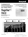
PROGRAMMABLE
THERMOSTAT
Honeywell
Thermostat patents pending.
Printed in Mexico • J.H. • ©Honeywell Inc. 1992
Weekday/Weekend
Programmable Heat and/or Cool
Thermostat and Mounting Plate
Model T8132
MagicStat
/
T8132
BY HONEYWELL
Rev. 9-92 • Form Number 69-0740B—1
PROGRAMMING AND INSTALLATION
INSTRUCTIONS
30%
28%
26%
24%
22%
20%
18%
16%
14%
12%
8%
6%
2%
10%
4%
Minneapolis
St. Paul
Montreal
Ottawa
Toronto
Buffalo
Cleveland
Milwaukee
Edmonton
Regina
Winnipeg
Calgary
Moncton
North Bay
Quebec
St. John's
Halifax Vancouver Denver
Des Moines
Omaha
Salt Lake
City
Boston
Chicago
Detroit
Pittsburgh
Indianapolis
Cincinnati
Kansas City
St. Louis
Columbus
New York
Philadelphia
Seattle
Louisville
Portland
Wash., D C
San
Francisco
Dallas
Atlanta
Los Angeles
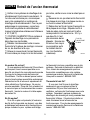
Approximate percentage of energy cost savings
Savings for Once-A-Day
10°F (5°C) decrease
Savings for Twice-A-Day
10°F (5°C) decrease*
Savings for 5°F (3°)
summer increase
TYPICAL ENERGY SAVINGS FOR REPRESENTATIVE CITIES IN THE U.S. AND CANADA
*Based on 10°F (5°C) decrease—(5°F (3°C) decrease
gives approximately 55 percent of these savings).
M2416A
San Diego

1
Welcome to the world of comfort and energy savings with your new Honeywell MagicStat
TM
programmable thermostat.
Your new thermostat will automatically control the temperature in your home, keeping you
comfortable while saving energy when programmed according to the instructions in this manual.
Any questions concerning the application of this thermostat should be directed to Honeywell
Customer Assistance at 1-800-468-1502, Monday-Friday 7:00 a.m.-5:30 p.m., Central time.
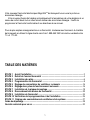
Table Of Contents
STEP 1 Prepare For Installation ............................................................................................... 2
STEP 2 Remove Old Thermostat .............................................................................................. 4
STEP 3 Install The Batteries ..................................................................................................... 6
STEP 4 Program The Thermostat ............................................................................................. 8
STEP 5 Adjust Fan Operation Switch, as Required .............................................................. 16
STEP 6 Adjust System On-Length as Required .................................................................... 16
STEP 7 Mount Thermostat Mounting Plate............................................................................ 18
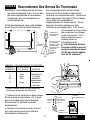
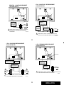
STEP 8 Wire Thermostat Terminals ....................................................................................... 20
STEP 9 Mount The Thermostat ............................................................................................... 24
STEP 10 Check Thermostat Operation After Programming and Installing ........................ 25
STEP 11 Set The Fan and System Switches ........................................................................ 27
Troubleshooting Guide............................................................................................................ 28
Limited One-Year Warranty ..................................................................................................... 33

1
Welcome to the world of comfort and energy savings with your new Honeywell MagicStat
TM
programmable thermostat.
Your new thermostat will automatically control the temperature in your home, keeping you
comfortable while saving energy when programmed according to the instructions in this manual.
Any questions concerning the application of this thermostat should be directed to Honeywell
Customer Assistance at 1-800-468-1502, Monday-Friday 7:00 a.m.-5:30 p.m., Central time.
Table Of Contents
STEP 1 Prepare For Installation ............................................................................................... 2
STEP 2 Remove Old Thermostat .............................................................................................. 4
STEP 3 Install The Batteries ..................................................................................................... 6
STEP 4 Program The Thermostat ............................................................................................. 8
STEP 5 Adjust Fan Operation Switch, as Required .............................................................. 16
STEP 6 Adjust System On-Length as Required .................................................................... 16
STEP 7 Mount Thermostat Mounting Plate............................................................................ 18
STEP 8 Wire Thermostat Terminals ....................................................................................... 20
STEP 9 Mount The Thermostat ............................................................................................... 24
STEP 10 Check Thermostat Operation After Programming and Installing ........................ 25
STEP 11 Set The Fan and System Switches ........................................................................ 27
Troubleshooting Guide............................................................................................................ 28
Limited One-Year Warranty ..................................................................................................... 33

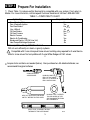
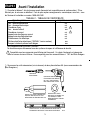
Prepare For Installation
■■ Check Table 1 to make sure this thermostat is compatible with your system. If not, return to
retailer. For more information, call Honeywell Customer Assistance, toll-free 1-800-468-1502.
TABLE 1—COMPATIBILITY CHART.
System Type Compatible With CT3200
Gas—Standing Pilot Yes
Gas—Electronic Ignition Yes
Gas-Fired Boilers Yes
1
Gas—Millivolt No
Oil-Fired Boilers Yes
1
Oil-Fired Furnace Yes
Electric Furnace Yes
Electric Air Conditioning Yes
Baseboard Electric (120/240 Line Volt) No
Heat Pumps/Multistage Equipment No
3
2
Not compatible with any 120/240 volt circuit.
Will not work efficiently on steam or gravity systems.
1
Compatible with 2-wire Honeywell zone valves. Isolating relay required for 3-wire thermo-
stats for zone valves. Not compatible with 2-wire White-Rodgers #1361 valves.
CROSS-RECESSED
SCREWDRIVER
HAND OR POWER
DRILL WITH 3/16 INCH
DRILL BIT, IF NEEDED TO
DRILL HOLES IN WALL
WIRE CUTTER/STRIPPER OR SHARP
KNIFE, IF NEEDED TO STRIP WIRES
MASKING TAPE, IF NEEDED
TO LABEL WIRES AS THEY
ARE DISCONNECTED FROM
OLD THERMOSTAT
SPIRIT LEVEL, IF NEEDED TO LEVEL
THERMOSTAT FOR APPEARANCE
M 878
■■ Acquire tools and items as needed (below). Also purchase two AA alkaline batteries; we
recommend Energizer batteries
STEP 1

4
5
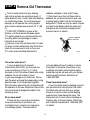
Remove Old Thermostat
not
compatible with such systems so return
the product to the place of purchase. If you
would like information about which program-
mable thermostats will work with your system,
call Honeywell Customer Assistance at
1-800-468-1502.
Three thermostat wires?
If you have three wires for heating only and
can operate the fan using the fan ON switch,
this thermostat will work with your system.
However, some hot water (zoned) heating
systems have three thermostat wires. The
thermostat will not work without installing an
isolating relay on these systems. Call Honey-
well Customer Assistance at 1-800-468-1502
for details.
■■ Test to make certain that your heating
and cooling systems are working properly. If
either does not work, contact your local heating/
air conditioning dealer. To avoid compressor
damage, do not operate the cooling system
when outdoor temperature is below 10° C [50°
F].
■■ TURN OFF POWER to system at the
furnace, or at the fuse/circuit breaker panel.
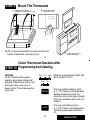
■■ Carefully unpack your new thermostat and
mounting plate; save package of screws,
instructions and receipt.
■■ Remove cover from old thermostat. If it does
not snap off when pulled firmly from the bottom,
check for a screw used to lock on the cover.
■■ Loosen screws holding thermostat to
subbase, wallplate or wall, and lift away.
■■ Disconnect wires from old thermostat or
subbase. As you disconnect each wire, use
masking tape to label it with the old terminal
designation. If there are only two wires, they do
not need to be labeled. Keep the wires from
falling back into the wall by wrapping them
around a pencil, as shown.
STEP 2
WIRES THROUGH
WALL OPENING
M5136
One or two extra wires?
If you are replacing a Honeywell
Chronotherm thermostat, you may find one
or two wires that go to the C or C1 clock
terminals on the Chronotherm thermostat wiring
wallplate. Do not allow them to touch,
or you may damage your transformer. Discon-
nect the wires and wrap them separately, using
electrical tape.
Do not wrap them together
.
Place the wires where they will not interfere with
the operation of the new thermostat. Record the
colors and terminal designation labels of the
remaining wires.
Six or more wires?
If there are six or more wires (excluding
clock wires attached to terminals), you
most likely have a variation of a heat pump
or multistage system. The thermostat is

4
5
Remove Old Thermostat
not
compatible with such systems so return
the product to the place of purchase. If you
would like information about which program-
mable thermostats will work with your system,
call Honeywell Customer Assistance at
1-800-468-1502.
Three thermostat wires?
If you have three wires for heating only and
can operate the fan using the fan ON switch,
this thermostat will work with your system.
However, some hot water (zoned) heating
systems have three thermostat wires. The
thermostat will not work without installing an
isolating relay on these systems. Call Honey-
well Customer Assistance at 1-800-468-1502
for details.
■■ Test to make certain that your heating
and cooling systems are working properly. If
either does not work, contact your local heating/
air conditioning dealer. To avoid compressor
damage, do not operate the cooling system
when outdoor temperature is below 10° C [50°
F].
■■ TURN OFF POWER to system at the
furnace, or at the fuse/circuit breaker panel.
■■ Carefully unpack your new thermostat and
mounting plate; save package of screws,
instructions and receipt.
■■ Remove cover from old thermostat. If it does
not snap off when pulled firmly from the bottom,
check for a screw used to lock on the cover.
■■ Loosen screws holding thermostat to
subbase, wallplate or wall, and lift away.
■■ Disconnect wires from old thermostat or
subbase. As you disconnect each wire, use
masking tape to label it with the old terminal
designation. If there are only two wires, they do
not need to be labeled. Keep the wires from
falling back into the wall by wrapping them
around a pencil, as shown.
STEP 2
WIRES THROUGH
WALL OPENING
M5136
One or two extra wires?
If you are replacing a Honeywell
Chronotherm thermostat, you may find one
or two wires that go to the C or C1 clock
terminals on the Chronotherm thermostat wiring
wallplate. Do not allow them to touch,
or you may damage your transformer. Discon-
nect the wires and wrap them separately, using
electrical tape.
Do not wrap them together
.
Place the wires where they will not interfere with
the operation of the new thermostat. Record the
colors and terminal designation labels of the
remaining wires.
Six or more wires?
If there are six or more wires (excluding
clock wires attached to terminals), you
most likely have a variation of a heat pump
or multistage system. The thermostat is

6
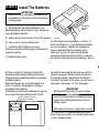
As the batteries are running low, a “bAt Lo” in-
dicator will flash for 1-2 months before batteries
run out completely. Replace the batteries as
soon as possible after the indicator starts
flashing. If you do not replace the batteries
sometime during the flashing “bAt Lo” indicator,
the indicator will eventually stop flashing. “bAt Lo”
will stay on without flashing to indicate the
thermostat and heating/cooling system have
stopped working when the batteries are almost
completely dead.
After the batteries are completely dead, the
“bAt Lo” indicator will disappear, leaving a
completely blank display.
Press down on left ends of batteries to remove.
If you insert the new batteries within 20-30
7
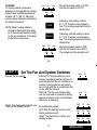
INSTALL TWO AA ALKALINE
BATTERIES AS SHOWN
M1713
STEP 3
M1719B
REMOVING
BATTERY
DOOR
Install The Batteries
IMPORTANT
Batteries must be installed for programming
and operation of the thermostat and heating/
cooling system.
■■ Purchase two AA alkaline batteries; non-
alkaline batteries will not last as long. We recom-
mend Energizer batteries.
■■ Make sure the thermostat is set in OFF position.
■■ Use a coin to remove battery door.
■■ Install the fresh batteries as shown,
making sure positive and negative terminals are
oriented correctly.
■■ Replace battery door.
seconds of removing the old ones, you will not
have to reprogram the thermostat. However, if
the display is blank, the batteries are dead or
incorrectly installed. In this case, you will have to
reprogram. See pages 12-13 to reprogram.
IMPORTANT
Although the thermostat has a low battery
indicator, replace the batteries once a year to
prevent the thermostat and heating/cooling
system from shutting down due to lack of
battery power.
When leaving home for longer than a month,
as a precaution, change batteries before you
leave to prevent system from shutting down due
to lack of battery power.

6
As the batteries are running low, a “bAt Lo” in-
dicator will flash for 1-2 months before batteries
run out completely. Replace the batteries as
soon as possible after the indicator starts
flashing. If you do not replace the batteries
sometime during the flashing “bAt Lo” indicator,
the indicator will eventually stop flashing. “bAt Lo”
will stay on without flashing to indicate the
thermostat and heating/cooling system have
stopped working when the batteries are almost
completely dead.
After the batteries are completely dead, the
“bAt Lo” indicator will disappear, leaving a
completely blank display.
Press down on left ends of batteries to remove.
If you insert the new batteries within 20-30
7
INSTALL TWO AA ALKALINE
BATTERIES AS SHOWN
M1713
STEP 3
M1719B
REMOVING
BATTERY
DOOR
Install The Batteries
IMPORTANT
Batteries must be installed for programming
and operation of the thermostat and heating/
cooling system.
■■ Purchase two AA alkaline batteries; non-
alkaline batteries will not last as long. We recom-
mend Energizer batteries.
■■ Make sure the thermostat is set in OFF position.
■■ Use a coin to remove battery door.
■■ Install the fresh batteries as shown,
making sure positive and negative terminals are
oriented correctly.
■■ Replace battery door.
seconds of removing the old ones, you will not
have to reprogram the thermostat. However, if
the display is blank, the batteries are dead or
incorrectly installed. In this case, you will have to
reprogram. See pages 12-13 to reprogram.
IMPORTANT
Although the thermostat has a low battery
indicator, replace the batteries once a year to
prevent the thermostat and heating/cooling
system from shutting down due to lack of
battery power.
When leaving home for longer than a month,
as a precaution, change batteries before you
leave to prevent system from shutting down due
to lack of battery power.

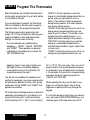
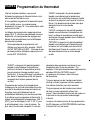
9
PROGRAMMING
STEP 4
Program The Thermostat
8
26° C [78° F], 24 hours a day. Also, you do not
need to enter a time and temperature program
for all periods if your schedule does not require
it. For example, a house that is occupied during
weekdays would not require programs for
“LEAVE” and “RETURN”.
When pressing the keys, use the ball of your
finger or a soft pencil eraser. Use of sharp
fingernails or pencil points may damage the
keypad.
If at any time during programming you make an
error, just press the RUN PROGRAM key, and
continue again at the step where you left off.
sleeping. (Again, lower heat or higher cool.
Although for more comfortable sleeping,
some people choose not to raise the cool
temperature during the night.)
You will set one schedule for weekdays and
another for weekends, since your requirements
will probably be different for each. Also, during
weekends only the “WAKE” and “SLEEP” time
periods are available.
Fill in the times and temperatures you desire for
weekdays and weekends. If you decide not to
program the thermostat, it will automatically
control heating at 20° C [68° F], and cooling at
After the batteries are installed, the thermostat
can be easily programmed in your hand, before
it is installed on the wall.
If you would prefer to program the thermostat
after it is installed on the wall, skip to page 16,
and return later to this programming section.
The following personal programming chart
(pages 10-11) may be helpful for planning your
program schedule of time and temperature
settings for various times of the day.
Four time periods are available during
weekdays — “WAKE”, “LEAVE”, “RETURN”,
and “SLEEP”. These periods can be seen
individually on the display as you press the
SET SCHEDULE key.
“WAKE” is the time period you want the
house at a comfortable temperature after you
get up, while you get ready for work or
school. (This will be a higher temperature
during heating season, or a lower tempera-
ture during cooling season.)
“LEAVE” is the time period you can set for an
energy-saving temperature while you are
away at work or school. (This will be a lower
temperature during heating season, or a
higher temperature during cooling season.)
“RETURN” is the time period you want the
house at a comfortable temperature for
activities before bedtime. (Again, higher heat
or lower cool.)
“SLEEP” is the time period you can set for an
energy-saving temperature while you are

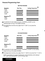
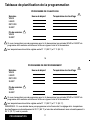
COOLING PROGRAM
Weekdays Start Time Cooling Temperature
WAKE
LEAVE
RETURN
SLEEP
Weekends
1
WAKE
SLEEP
1
If you decide not to enter weekend programs, the WAKE and SLEEP from the weekday
program will copy to the weekend schedule.
2
The temperatures cannot be set any higher than 31° C [88° F] or any lower than 7° C [45° F].
NOTE: If you decide not to program the thermostat, it will automatically control heating at
20° C [68° F], and cooling at 26° C [78° F], 24 hours a day.
11
PROGRAMMING
10
HEATING PROGRAM
Weekdays Start Time Heating Temperature
WAKE
LEAVE
RETURN
SLEEP
Weekends
1
WAKE
SLEEP
1
If you decide not to enter weekend programs, the WAKE and SLEEP from the
weekday program will copy to the weekend schedule.
2
The temperatures cannot be set any higher than 31° C [88° F] or any lower than
7° C [45° F].
Personal Programming Chart
2
2

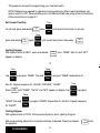
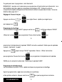
Heating Program
With system switch at HEAT, press and release once. “WAKE”, Mon-Fri and “SET”
appear on display.
Use to program “WAKE” time and to program “WAKE” temperature for
Mon-Fri. Repeat sequence for “LEAVE”, “RETURN”, “SLEEP”.
PROGRAMMING
This guide can be used for programming your new thermostat.
NOTE: Batteries are required for operation and programming. When inserting batteries, set
system switch to OFF. Remove battery door (on thermostat left side) using a coin at the bottom.
Follow instructions on pages 6-7.
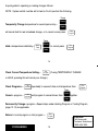
Set Current Time/Day
12
Warmer
Cooler
13
Run
Program
Ahead
Back
Time
Temp
To set time, press and release once, until current time shows; to set day,
press and release again, until current day shows; then press .
Set
Clock/Day
Ahead
Back
Time
Set
Clock/Day
Ahead
Back
Time
Run
Program
Set
Schedule
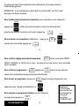
Cooling Program
With system switch at COOL, follow same instructions as for Heating Program.
After programming, adjust fan and system switches as desired. Press and release to start
the program.
Press until “WAKE”, “SA SU” and “SET” appear on display. Use to program
“WAKE” time and to program “WAKE” temperature for Sat-Sun. Repeat sequence
for “SLEEP”.
Set
Schedule
Warmer
Cooler
Temp
Ahead
Back
Time

Heating Program
With system switch at HEAT, press and release once. “WAKE”, Mon-Fri and “SET”
appear on display.
Use to program “WAKE” time and to program “WAKE” temperature for
Mon-Fri. Repeat sequence for “LEAVE”, “RETURN”, “SLEEP”.
PROGRAMMING
This guide can be used for programming your new thermostat.
NOTE: Batteries are required for operation and programming. When inserting batteries, set
system switch to OFF. Remove battery door (on thermostat left side) using a coin at the bottom.
Follow instructions on pages 6-7.
Set Current Time/Day
12
Warmer
Cooler
13
Run
Program
Ahead
Back
Time
Temp
To set time, press and release once, until current time shows; to set day,
press and release again, until current day shows; then press .
Set
Clock/Day
Ahead
Back
Time
Set
Clock/Day
Ahead
Back
Time
Run
Program
Set
Schedule
Cooling Program
With system switch at COOL, follow same instructions as for Heating Program.
After programming, adjust fan and system switches as desired. Press and release to start
the program.
Press until “WAKE”, “SA SU” and “SET” appear on display. Use to program
“WAKE” time and to program “WAKE” temperature for Sat-Sun. Repeat sequence
for “SLEEP”.
Set
Schedule
Warmer
Cooler
Temp
Ahead
Back
Time

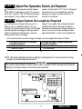
Check Current Temperature Setting— . (If using TEMPORARILY CHANGE
or HOLD, pressing this will cancel your change.)
Check Programs— repeatedly to see each time and temperature; then .
Cancel a program— until program to cancel shows; then together.
Permanently Change a program—Repeat steps under Heating Program or Cooling Program
(page 12-13) as applicable.
Return to normal program or start program — .
Temporarily Change temperature for current period only— ;
will cancel itself at next scheduled change, or to cancel sooner press .
Hold a temperature indefinitely— , ; to cancel press .
PROGRAMMING
A quick guide for operating or making changes follows:
NOTE: System switch must be set to Heat or Cool to perform the following.
14
Set
Schedule
Run
Program
Set
Schedule
Run
Program
Ahead
Back
Time
Hold
Temp
Warmer
Cooler
Temp
Warmer
Cooler
Temp
Run
Program
Run
Program
Run
Program
15
Questions?
Call Honeywell
Customer Assistance
1-800-468-1502.

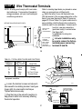
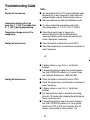
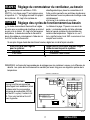
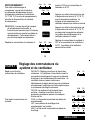
If on-length screws A,B are adjusted For longer on-length, readjust screws A,B
to match this system: to match this system:
electric furnace warm air furnace
warm air furnace hot water boiler
NOTE: This thermostat does not have a setting for steam/gravity air. Cycles would not be long
enough for accurate temperature control.
IMPORTANT
When using a high efficiency furnace such as a 90% or greater AFUE (Average Fuel Utilization
Efficiency) unit, adjust screw A out one turn and screw B in.
INSTALLATION
16
17
Adjust System On-Length As Required
STEP 5
STEP 6
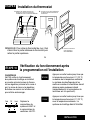
Adjust Fan Operation Switch, As Required
■■ The thermostat fan operation switch, labeled
FUEL SWITCH (see figure on page 17) is factory-
set in the “F” position. This is the correct setting for
most systems. If your system is an electric heat
system, set the switch to “E”. The “E” setting will
allow the fan to turn on immediately with the
heating or cooling in a system where the “G”
terminal is connected.
■■ The thermostat on-length is factory-set for a
warm air, gas or oil heating system. If you are
installing it on another type of system, the on-length
must be adjusted accordingly by setting screws A
and B on the back of the thermostat, using the
heating system table in the figure
(page 17) as a guide. The on-length should be
optimized according to the type of system to
minimize room temperature swings. Setting the
screw “out one turn” means turning the screw
approximately 360°, or about one complete turn.
In the rare event that you want a longer on-length, you may readjust the screws as follows:
R
Rc
W Y G
B D
A C
THERMOSTAT BACK
DISPLAY °F
DISPLAY °C
C–IN
C–OUT
1 TURN
FOR HIGH EFFICIENCY FURNACE (90%+ AFUE)
ADJUST: SCREW A–OUT 1 TURN
SCREW B–IN
FUEL SWITCH – F POSITION
F
E
FUEL SWITCH
WARM AIR
FURNACE
HOT WATER
BOILER
ELECTRIC
FURNACE
A–IN
A–OUT
1 TURN
A–IN
ADJUST SCREWS THROUGH HOLES
TO SELECT OPERATION DESIRED
B–IN
B–IN
B–OUT
1 TURN
FUEL SWITCH
POSITION
F
F
E
HEATING SYSTEM

If on-length screws A,B are adjusted For longer on-length, readjust screws A,B
to match this system: to match this system:
electric furnace warm air furnace
warm air furnace hot water boiler
NOTE: This thermostat does not have a setting for steam/gravity air. Cycles would not be long
enough for accurate temperature control.
IMPORTANT
When using a high efficiency furnace such as a 90% or greater AFUE (Average Fuel Utilization
Efficiency) unit, adjust screw A out one turn and screw B in.
INSTALLATION
16
17
Adjust System On-Length As Required
STEP 5
STEP 6
Adjust Fan Operation Switch, As Required
■■ The thermostat fan operation switch, labeled
FUEL SWITCH (see figure on page 17) is factory-
set in the “F” position. This is the correct setting for
most systems. If your system is an electric heat
system, set the switch to “E”. The “E” setting will
allow the fan to turn on immediately with the
heating or cooling in a system where the “G”
terminal is connected.
■■ The thermostat on-length is factory-set for a
warm air, gas or oil heating system. If you are
installing it on another type of system, the on-length
must be adjusted accordingly by setting screws A
and B on the back of the thermostat, using the
heating system table in the figure
(page 17) as a guide. The on-length should be
optimized according to the type of system to
minimize room temperature swings. Setting the
screw “out one turn” means turning the screw
approximately 360°, or about one complete turn.
In the rare event that you want a longer on-length, you may readjust the screws as follows:
R
Rc
W Y G
B D
A C
THERMOSTAT BACK
DISPLAY °F
DISPLAY °C
C–IN
C–OUT
1 TURN
FOR HIGH EFFICIENCY FURNACE (90%+ AFUE)
ADJUST: SCREW A–OUT 1 TURN
SCREW B–IN
FUEL SWITCH – F POSITION
F
E
FUEL SWITCH
WARM AIR
FURNACE
HOT WATER
BOILER
ELECTRIC
FURNACE
A–IN
A–OUT
1 TURN
A–IN
ADJUST SCREWS THROUGH HOLES
TO SELECT OPERATION DESIRED
B–IN
B–IN
B–OUT
1 TURN
FUEL SWITCH
POSITION
F
F
E
HEATING SYSTEM

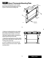
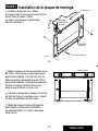
Mount Thermostat Mounting Plate
19
18
INSTALLATION
STEP 7
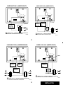
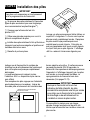
■■ Position mounting plate on wall. Use spirit
level to make sure mounting plate is level. Use
a pencil to mark the two mounting holes.
■■ Remove mounting plate from wall, and drill
3/16" holes in wall (if drywall) as marked. For
firmer material such as plaster or wood, drill
7/32" holes. Gently tap anchors (provided) into
drilled holes until flush with the wall.
■■ Reposition mounting plate over holes, pulling
wires through wiring opening. Loosely insert two
mounting screws into holes.
■■ Level for appearance only; thermostat will
function properly even when not level. Tighten
mounting screws.
WALL
WIRES THROUGH
WALL OPENING
WALL
ANCHORS (2)
MOUNTING
PLATE
MOUNTING
SCREWS
(
2
)
M1718
SPIRIT LEVEL
M1714
La page est en cours de chargement...
La page est en cours de chargement...
La page est en cours de chargement...
La page est en cours de chargement...
La page est en cours de chargement...
La page est en cours de chargement...
La page est en cours de chargement...
La page est en cours de chargement...
La page est en cours de chargement...
La page est en cours de chargement...
La page est en cours de chargement...
La page est en cours de chargement...
La page est en cours de chargement...
La page est en cours de chargement...
La page est en cours de chargement...
La page est en cours de chargement...
La page est en cours de chargement...
La page est en cours de chargement...
La page est en cours de chargement...
La page est en cours de chargement...
La page est en cours de chargement...
La page est en cours de chargement...
La page est en cours de chargement...
La page est en cours de chargement...
La page est en cours de chargement...
La page est en cours de chargement...
La page est en cours de chargement...
La page est en cours de chargement...
La page est en cours de chargement...
La page est en cours de chargement...
La page est en cours de chargement...
La page est en cours de chargement...
La page est en cours de chargement...
La page est en cours de chargement...
La page est en cours de chargement...
La page est en cours de chargement...
La page est en cours de chargement...
La page est en cours de chargement...
La page est en cours de chargement...
La page est en cours de chargement...
La page est en cours de chargement...
La page est en cours de chargement...
La page est en cours de chargement...
La page est en cours de chargement...
La page est en cours de chargement...
La page est en cours de chargement...
La page est en cours de chargement...
La page est en cours de chargement...
La page est en cours de chargement...
La page est en cours de chargement...
La page est en cours de chargement...
La page est en cours de chargement...
-
 1
1
-
 2
2
-
 3
3
-
 4
4
-
 5
5
-
 6
6
-
 7
7
-
 8
8
-
 9
9
-
 10
10
-
 11
11
-
 12
12
-
 13
13
-
 14
14
-
 15
15
-
 16
16
-
 17
17
-
 18
18
-
 19
19
-
 20
20
-
 21
21
-
 22
22
-
 23
23
-
 24
24
-
 25
25
-
 26
26
-
 27
27
-
 28
28
-
 29
29
-
 30
30
-
 31
31
-
 32
32
-
 33
33
-
 34
34
-
 35
35
-
 36
36
-
 37
37
-
 38
38
-
 39
39
-
 40
40
-
 41
41
-
 42
42
-
 43
43
-
 44
44
-
 45
45
-
 46
46
-
 47
47
-
 48
48
-
 49
49
-
 50
50
-
 51
51
-
 52
52
-
 53
53
-
 54
54
-
 55
55
-
 56
56
-
 57
57
-
 58
58
-
 59
59
-
 60
60
-
 61
61
-
 62
62
-
 63
63
-
 64
64
-
 65
65
-
 66
66
-
 67
67
-
 68
68
-
 69
69
-
 70
70
-
 71
71
-
 72
72


Honeywell T8132 Le manuel du propriétaire
- Catégorie
- Thermostats
- Taper
- Le manuel du propriétaire
dans d''autres langues
- English: Honeywell T8132 Owner's manual
Documents connexes
-
Honeywell TH4000 Le manuel du propriétaire
-
Honeywell RTHL221 series Manuel utilisateur
-
-
Honeywell RTHL2410 series Le manuel du propriétaire
-
Honeywell RTH4300B Le manuel du propriétaire
-
Honeywell TH2000 Manuel utilisateur
-
-
-
Honeywell FocusPRO TH6320U Manuel utilisateur
-

