Waterford JSAL210D Le manuel du propriétaire
- Catégorie
- Accessoires de piscine hors terre
- Taper
- Le manuel du propriétaire

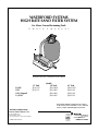
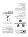
WATERFORD SYSTEMS
HIGH RATE SAND FILTER SYSTEM
For Above Ground Swimming Pools
O W N E R ’ S M A N U A L
INSTALLATION, OPERATION & PARTS
Sta-Rite Pool/Spa Group
293 Wright Street, Delavan, WI 53115
International: 262-728-5551, FAX: 262-728-7550
www.starite.com
Union City, TN • Delavan, WI • Mississauga, ON
© 2006, Sta-Rite Industries
S260 (Rev. 4/26/06)
839 0494
Models
15" Tank 18" Tank 21" Tank
3/4 HP JSAL15D JSAL180D JSAL210D
1 HP JSAL15E JSAL180E JSAL210E
1 HP (2-Speed) JSAL180E JSAL210E
1-1/2 HP JSAL180F JSAL210F
This manual should be furnished to the end user
of this system; its use will reduce service calls and
chance of injury and will lengthen system life.
P
entair P
ool Pr
oducts,
Inc.
1620 Ha
wkins Ave.
Sanf
ord, NC 27330
Tel 919-774-4151 • Fax 919-774-4841
S260 (Re
v
.
B 6/28/06)

2
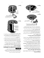
HIGH-RATE SAND FILTER SYSTEM
To avoid unneeded service calls, prevent possible injuries, and get the most out
of your filter, READ THIS MANUAL CAREFULLY!
The High Rate Sand Filter System:
• Is designed to circulate and filter water in above ground swimming pools.
• Offers quiet, efficient performance and is durable, reliable.
• With a 3’ cord or no cord, use with permanently installed pools ONLY
(see CAUTION #7, below).
• With a 25’ cord, use with storable pools ONLY (see CAUTION #8, below).
Table of Contents
Safety Instructions.......................................................................................................3
Specifications/Dimensional Data...............................................................................4
General Information..................................................................................................5
Installation.............................................................................................................5-7
Filter Mount/Piping ................................................................................................5
Filter Set-up ...........................................................................................................6
Loading Sand Media ..............................................................................................6
Valve Installation................................................................................................6-7
Electrical ..................................................................................................................7
Startup/Operation/Backwash..................................................................................8-9
Maintenance.............................................................................................................9
Storage/Winterizing ................................................................................................10
Multi-Port Valve Service .........................................................................................11
Valve Removal .......................................................................................................11
Pump Service ....................................................................................................11-12
Troubleshooting Guide ...........................................................................................13
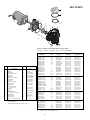
Repair Parts List .................................................................................................14-17
Warranty ................................................................................................................18
IMPORTANT SAFETY INSTRUCTIONS
When installing and using electrical equipment, basic safety precautions should always be followed,
including the following:
SAVE THESE INSTRUCTIONS
1. READ AND FOLLOW ALL SAFETY INSTRUCTIONS.
2. To reduce the risk of injury, do not permit
children to use this product unless they are closely super-
vised at all times.
3. Risk of electrical shock. Connect only to a
grounding type receptacle protected by a ground-fault cir-
cuit-interrupter (GFCI). Contact a qualified electrician if you
cannot verify that the receptacle is protected by a GFCI.
4. Do not bury cord. Locate cord to minimize abuse from
lawn mowers, hedge trimmers, and other equipment.
5. To reduce the risk of electrical shock,
replace a damaged cord immediately.
6.
To reduce the risk of electrical shock, do
not use an extension cord to connect unit to electrical sup-
ply; provide a properly located outlet.
7. Permanent pumps are for use with perma-
nently installed pools and may also be used with hot tubs
and spas if so marked. Do not use with storable pools. A
permanently installed pool is constructed in or on the
ground or in a building such that it cannot be readily dis-
assembled for storage. A storable pool is constructed so that
it may be readily disassembled for storage and reassembled
to its original integrity.
8. Storable pool pumps are for use with
storable pools only. Do not use with permanently installed
pools. A storable pool is constructed so that it is capable
of being readily disassembled for storage and reassembled
to its original integrity. A permanently installed pool is
constructed in or on the ground, or in a building, such that
it cannot be readily disassembled for storage.

3
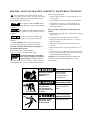
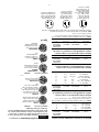
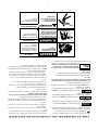
This is the safety-alert symbol. When you see
this symbol on your valve or in this manual, look
for one of the following signal words and be alert to
the potential for personal injury.
warns about hazards that will cause se-
rious personal injury, death or major property damage
if ignored.
warns about hazards that can cause seri-
ous personal injury, death or major property damage
if ignored.
warns about hazards that will or can
cause minor personal injury or property damage if
ignored.
The label NOTICE indicates special instructions
which are important but not related to hazards.
Carefully read and follow all safety instructions in
this manual and on system.
Keep safety labels in good condition.
Replace missing or damaged safety labels.
Incorrectly installed or tested equip-
ment may fail, causing severe injury or
property damage. Read and follow in-
structions in owner's manual when installing and op-
erating equipment. Have a trained pool professional
perform all pressure tests.
1. Do not connect system to a high pressure or city
water system.
2
. Use equipment only in a pool or spa installation.
3. Trapped air in system can cause explosion. BE
SURE all air is out of system before operating or
testing equipment.
Before pressure testing, make the following safety
checks:
• Check all clamps, bolts, lids, and system accessories
before testing.
• BE SURE all air is out of system before testing.
• Tighten Sta-Rite trap lids to 30 ft. lbs. (4.1 kg-cm)
torque for testing.
• Water pressure for test must be less than 25 PSI
(172 kPa).
• Water temperature for test must be less than 95˚ F.
(35˚ C).
• Limit test to 24 hours. After test, visually check sys-
tem to be sure it is ready for operation. Remove trap
lid and retighten hand tight only.
NOTICE: These parameters apply to Sta-Rite equip-
ment only. For non-Sta-Rite equipment, consult
manufacturer.
Hazardous Pressure!
Can cause tank
explosion.
WHEN USING SYSTEM:
Do not test with
compressed air
or operate above
rated pressure.
Hazardous voltage.
Can shock, burn,
or cause death.
BEFORE WORKING
ON PUMP OR MOTOR:
Unplug pump motor.
Hazardous suction.
Can trap or tear
hair or body parts,
causing severe injury
or death.
WHEN USING SYSTEM:
Do not block pump
suction or pool main
drain.
READ AND FOLLOW SAFETY INSTRUCTIONS!

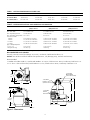
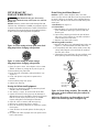
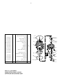
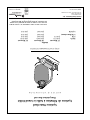
1-1/2" NPT
Return to Pool
(Union Connection)
1-1/2" NPT
Suction
Connection
1-1/2" NPT
Waste Outlet
(Union Connection)
23
2-13/16
A
B
7
11
1278 0994
Drain
(To Tank
Flange)
D
2-5/16
9-1/16
11-1/4
Tank
Dia.
C
E
1279 0994
4
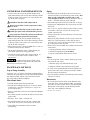
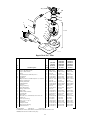
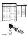
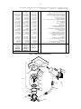
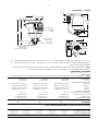
TABLE I - OUTLINE DIMENSIONS IN INCHES (mm)
Filter Model A B C D E
15”(406mm) Filters 24 (610) 30-7/8 (784) 15-3/4 (400) 21-11/16 (551) 26-1/16 (662)
18”(457mm) Filters 26-9/16 (675) 33-5/16 (846) 17-3/4 (451) 24-1/4 (616) 27-1/16 (692)
21” (508mm) Filters 28-11/16 (729) 34-7/16 (875) 20-3/4 (527) 26-3/8 (670) 28-9/16 (725)
TABLE ll - FILTER SPECIFICATIONS AND OPERATING INFORMATION
FILTER MODEL: 15” 18” 21”
(JSAL15 Series) (JSAL180 Series) (JSAL210 Series)
Effective Filter Area 1.26 Ft.
2
(.117M
2
) 1.57 Ft.
2
(.223M
2
) 2.18 Ft.
2
(.203M
2
)
Max. Flow Rate 25.2 GPM(95 L/m) 31.5 GPM(123 L/m) 43.6 GPM(165 L/m)
Max. Operating Pressure 50 PSI(345 kPa) 50 PSI(345 kPa) 50 PSI(345 kPa)
M
ax. Operating Temperature 95° F(35°C) 95° F(35°C) 95° F(35°C)
Turnover in Hours:
6 Hours 9,070 Gal.(34 330 liters) 11,340 Gal.(42 922 liters) 15,700 Gal.(59 424 liters)
8 Hours 12,100 Gal.(45 799 liters) 15,120 Gal.(57 229 liters) 20,930 Gal.(79 220 liters)
10 Hours 15,120 Gal.(57 229 liters) 18,900 Gal.(71 536 liters) 26,160 Gal.(99 016 liters)
12 Hours 18,144 Gal.(68 675 liters) 22,680 Gal.(85 844 liters) 31,390 Gal.(118 811 liters)
Qty. of Media Required:
Cu. Ft. (cm
3
) 1(28 320cm
3
) 1.5(42 255cm
3
) 2(56 923cm
3
)
Weight in lbs.(kg) 100(45,4 kg) 150(68 kg) 200(90,7 kg)
NOTE: 1 cubic foot (28 320 cm
3
) of sand weighs approximately 100 lbs. (45,4kg). DO NOT use a finer grade of sand than recommended.
RECOMMENDED SAND GRADES:
Use only: #20 Silica Sand, Size Range .40-.55mm., Uniformity Coefficient less than 1.75.
NOTICE: Use of other sands will reduce filter performance, may damage pump, and will void warranty.
Recommended:
1. Wedron Silica/Best Sand Co., Sand Grade: Wedron .45-.55mm., Effective Size .46mm, Uniformity Coefficient 1.22.
2. U.S. Silica - Silurian Filter Sand, Sand Grade.45-.55 mm., Effective Size .48mm, Uniformity Coefficient 1.18.
Figure 1: Dimensions

5
GENERAL INFORMATION
• Clean a new pool as well as possible before filling
pool and operating filter. Excess dirt and large particles
of foreign matter in the system can cause serious dam-
age to the filter and pump.
NEVER test this filter with compressed air.
Do not operate filter at water temperatures above
95°F (35°C).
NEVER operate this filter system at more than 50
pounds per square inch (50 PSI/345 kPa) pressure!
Plug system into electrically isolated, Ground Fault
Circuit Interrupter protected circuit ONLY!
• Clean a new pool as well as possible before filling
pool and operating filter. Excess dirt and large particles
of foreign matter in the system can cause serious dam-
age to the filter and pump.
• Keep pool water pH at recommended level (7.2 to 7.6)
to avoid irritation to eyes and skin.
• The Hi-Rate Sand Filter System is designed for use
with above ground swimming pools only.
• Use only #20 Silica sand with a screen mesh of .45
to .55mm. Use of other sands will reduce filter
performance.
To reduce risk of electric shock, install
pump at least 10 feet from the inside wall of the pool.
Do not use an extension cord.
INSTALLATION
Trap to Pump Assembly:
Using four 5/16” cap screws, flat washers and lockwashers,
mount trap to pump body; be sure to install gasket between
trap and pump body. Tighten cap screws to 80 inch-lbs
(92 cm-kg) torque; do not overtighten.
Filter Mount Must:
• Provide weather and freezing protection.
• Provide space and lighting for easy access for routine
maintenance. (See Table I and Figure 1, Page 4, for
space requirements.)
• Be on a reasonably level surface and provide adequate
drainage.
• Be as close to pool as possible to reduce line loss from
pipe friction.
• Be solid – level– rigid – vibration free.
• Be installed so that trap suction inlet is below pool
water level at all times. This allows pump to prime.
• Have adequate ventilation to prevent motor
overheating.
Piping:
• Use teflon tape or Plasto-Joint Stik
1
on all male con-
nections of plastic pipe and fittings except unions. DO
NOT use pipe compounds on plastic pipe; it will
cause the pipe to crack. Do not use sealant or tape on
u
nions – assemble them dry and hand tight.
• Do not damage union sealing surfaces and “O” Rings.
• Support pipe independently to prevent strains on filter
and valve.
• Use 1-1/2 or 2" pipe to reduce pressure losses as much
as possible. If flex hose is used, use the type with
smooth internal walls.
• Fittings restrict flow; for best efficiency use fewest pos-
sible fittings.
• Keep piping tight and free of leaks: pump suction line
leaks may cause trapped air in filter tank or loss of
prime at pump; pump discharge line leaks may show
up as dampness or jets of water.
• When unions are provided, use as follows for leak free
connections:
1. O-Ring and sealing surfaces must be clean.
2. Assemble hand tight only (no wrenches).
3. No pipe compound or teflon tape on unions.
Valves:
• For servicing filter system and for cleaning pump trap,
install ball or gate valves
A. Between pump trap and pool skimmer, and
B. Between selector valve and return pipe to pool.
• A check valve installed between filter and heater will
prevent hot water from backing up into filter and de-
forming internal components.
• Use care before assembly not to damage union sealing
surfaces or O Ring.
Wastewater:
• Be sure all provisions for waste water disposal meet
applicable local, state or national codes. 100 gallons
(379 liters) or more of pool water will be discharged
during filter backwashing. Do not discharge where
water will cause flooding or damage.
1
Lake Chemical Co., Chicago, IL

6
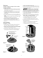
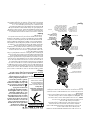
Filter Setup
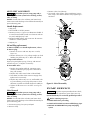
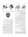
Assembly: See Figures 2 through 5 for filter assembly.
Loading Sand Media
1. To keep sand out of collector assembly, place plastic
s
and shield over top of collector tube before pouring
sand into filter (See Figure 5).
2. To support laterals and prevent lateral breakage dur-
ing loading, fill tank about half full of water before
loading sand.
3. Pour sand into filter tank. See “Recommended Sand
Grades”, Page 4, for correct type and quantity of sand
to use.
NOTICE: Make sure gasket area on top of tank is free
of sand before installing valve and clamp.
4. Before installing valve, double-check that correct
quantity of sand has been loaded (see Page 4).
5. Remove plastic sand loading shield and keep for fu-
ture use.
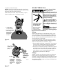
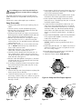
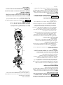
Valve Installation:
See Figures 6, 7, and 8
1. Install O-Ring on valve flange; make sure O-Ring is
clean, dry, and has no nicks, tears, or scrapes.
2. Make sure tank and valve flanges are clean and free of
sand; put valve on top of tank. Vertical pipe of collec-
tor assembly inserts into base of valve.
3. Install clamp; make sure knob is positioned for easy
access for filter maintenance. Valve port labeled
“
PUMP” should point toward pump.
4
. Tighten clamp knob until clamp ends (under bolt) are
1/4" (6mm) apart. Tap around outside of clamp with a
mallet to help seat clamp.
Hazardous pressure. Clamp will not
hold unless it is seated properly! DO NOT START
PUMP until clamp ends are 1/4" (6mm) apart or less.
5. If clamp will not pull up to 1/4" (6mm) gap, wait
15-30 minutes and retighten. Tap clamp gently with
mallet to help seat clamp.
6. Connect pipe from pump discharge to valve port la-
beled “PUMP”; use union half provided. Assemble
union as follows for leakfree operation:
A. O-Ring and sealing surfaces must be clean.
B. Assemble hand tight only (no wrenches).
C. NO pipe compound or teflon tape on unions.
7. Complete all plumbing connections (see Page 5 for
piping requirements).
A. Pipe from valve RETURN port to pool return.
B. Pipe from valve WASTE port to waste.
C. Suction piping from pool to trap inlet on pump.
B. Insert assembly
into top of
filter tank.
A. Insert first lateral into socket;
twist clockwise 1/4 turn
to lock lateral into hub.
Lateral is correctly installed
when slots face down.
731 0294
C. Hold assembly up
near top of tank and
add remaining
laterals.
732 0294
D. After all
laterals are
securely in
sockets,
position
assembly on
centering
boss in
bottom of
tank.
733 0294
S
A
N
D
::::
::::
::::
::::
::::
::::
::::
::::
::::
::::
::::
::::
::::
::::
::::
::::
::::
::::
::::
::::
::::
::::
::::
::::
::::
::::
::::
::::
::::
::::
::::
::::
::::
::::
::::
::::
::::
::::
::::
::::
::::
::::
::::
::::
::::
::::
::::
::::
::::
::::
::::
::::
::::
::::
::::
::::
::::
::::
::::
::::
::::
::::
::::
::::
::::
::::
::::
::::
::::
::::
::::
::::
::::
::::
::::
::::
::::
::::
::::
::::
::::
::::
::::
::::
::::
::::
::::
::::
::::
::::
::::
::::
::::
::::
::::
::::
::::
::::
::::
::::
::::
::::
::::
::::
::::
::::
::::
::::
::::
::::
::::
::::
::::
::::
::::
::::
::::
::::
::::
::::
::::
::::
::::
::::
::::
::::
::::
::::
::::
::::
::::
::::
::::
::::
::::
::::
::::
::::
::::
::::
::::
::::
::::
::::
::::
::::
::::
::::
::::
::::
::::
::::
::::
::::
::::
::::
::::
::::
::::
::::
::::
::::
::::
::::
::::
::::
::::
::::
::::
::::
::::
::::
::::
::::
::::
::::
::::
::::
::::
::::
::::
::::
::::
Fill tank
about
half full
of water
before
adding
sand.
Sand Shield
keeps collector
hub assembly
clean when
loading filter.
734 0294
Figure 2
Figure 3
Figure 4
Figure 5

7
8. System is ready for startup.
NOTICE: If there are leaks from beneath valve/clamp
area, STOP PUMP, release all pressure, remove clamp
and valve and clean sealing surfaces.
Follow directions under “Valve Installation”, Page 6,
when reinstalling valve. See Figures 6 and 7.
ELECTRICAL
Risk of electrical shock.
Plug pump into a
grounded, GFCI-protected 115
Volt circuit only. Incorrect volt-
age can cause fire or seriously
damage motor and voids war-
ranty. Protect cord from water
and physical damage.
GFCI tripping indicates
an electrical problem. If
GFCI trips and will not reset,
have a qualified electrician in-
spect and repair electrical sys-
tem.
Risk of electrical
shock. Unplug motor before
servicing or repairing pump or
motor.
Wiring:
Install a Ground Fault Circuit Interrupter (GFCI) in cir-
cuit; it will sense a short-circuit to ground and discon-
nect power before it becomes dangerous to pool users.
For size of GFCI required and test procedures for GFCI,
see manufacturer’s instruction.
In case of power outage, check GFCI for tripping (which
will prevent normal water circulation). Reset if necessary.
Match circuit breaker size to Table III, Page 8.
• Do not modify cord, plug, or receptacle. If an existing
circuit must be used and the receptacle and plug do
not match exactly, consult a licensed electrician.
• Do not use an extension or drop cord with this system;
it could cause a fire hazard or low voltage problems.
Wet cords cause shock hazards. Extension cords can
easily become cut or frayed and dangerous when
placed across yard areas or walkways.
Voltage:
Voltage at motor must be not more than 10% above or
below motor nameplate rated voltage or motor may
overheat, causing overload tripping and reduced compo-
nent life. If voltage is less than 90% or more than 110%
of rated voltage when motor is running at full load, con-
sult power company.
RR
EE
CC
II
R
R
C
C
U
U
L
L
AA
TT
EE
BB
AA
CC
KK
W
W
A
A
SS
H
H
EE
WW
A
A
S
S
T
T
E
E
FF
I
I
LL
TT
EE
R
R
1. Install O-Ring
on valve flange.
2. Install valve on tank.
Tank flange must
be clean; insert
collector pipe
into bottom
of valve.
Delavan, WI.
53115
USA
1/4" Max.
Port labeled
"PUMP" should
point toward
pump.
Install clamp
and tighten
until clamp
ends (under
bolt) are 1/4"
apart.
If unable to
close gap
to 1/4" or less,
wait 15-30
minutes and
retighten.
Tap around
clamp while
tightening to
help seat
clamp.
.WATERFORD, WI.
53185
U
SA
736 0294
R
R
EE
CC
I
I
RR
C
C
U
U
LL
AA
TT
EE
B
B
AA
C
C
KK
W
W
AA
SS
H
H
EE
WW
AA
S
S
TT
E
E
FF
I
I
LL
T
T
EE
R
R
Figure 6
Figure 7
Hazardous voltage.
Can shock, burn,
or cause death.
Disconnect power
before working
on pump or motor.

8
Table III–Recommended Fusing Data, 115 Volt 60 Hz Motors.
B
ranch
Pump Motor Full Load Circuit Breaker
M
odel No. H.P. Amps Rating (Amps)
JWPA5DC-2A3 3/4 9.4 15
JWPA5EC-2A3 1 11.9 15
J
WPS5FC-2A3 1-1/2SPL 11.9 15
1
7290-J1002 (2-Speed) 1 – 1/6 11.6/3.3 15
NOTICE: Values given are for pump motor only. Do not put
any other accessories on this circuit.
Table IV–Recommended Fusing Data, 115 Volt 60 Hz Single
Speed Motors.
Branch
Pump Motor Full Load Circuit Breaker
Model No. H.P. Amps Rating (Amps)
ABGS4EL-A2 1SPL 9.0 15
JWPA5DL-2A1, -2A2 3/4 9.0 15
JWPS5EL-A2 1SPL 9.0 15
JWPA5EL-2A1, -2A2 1 12.0 15
JWPAS5F-2A4U 1-1/2 SPL 12.0 15
JWPS5FL-A2 1-1/2 SPL 12.0 15
JWPA5FL-2A1, -2A2 1-1/2 16.0 20
Table V–Recommended Fusing Data, 230 Volt 60 Hz Motors.
Branch
Pump Motor Full Load Circuit Breaker
Model No. H.P. Amps Rating (Amps)
JWPA5E-230A2 1 6.1 15
Table VI–Recommended Fusing Data, 115 Volt 60 Hz 2-Speed
Motors.
Branch
Pump Motor Full Load Circuit Breaker
Model No. H.P. Amps Rating (Amps)
JWPA5YEL 1 / 1/8 11.7/3.39 15
JWPA5YFL 1-1/2 / 1/6 16.6/3.6 25
NOTICE Values given are for pump motor only. Do not put any
other accessories on this circuit.
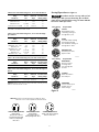
Startup/Operation
(
See Figure 9)
Hazardous suction. Can trap and tear hair
or body parts and can cause drowning. Do not block
pump suction. Small children using pool must ALWAYS
h
ave close adult supervision.
R
E
C
I
R
C
U
L
A
T
E
B
A
C
K
W
A
S
H
C
L
O
S
E
D
W
I
N
T
E
R
I
Z
E
W
A
S
T
E
F
I
L
T
E
R
R
I
N
S
E
Valve Setting
P
urpose/Flow
FILTER
Normal filtration and
v
acuuming; water goes
t
hrough filter to pool.
RINSE
F
or initial startup cleaning
and sand bed leveling
after backwash; water goes
through filter to waste.
RECIRCULATE
Circulates pool water;
bypasses filter.
R
E
C
I
R
C
U
L
A
T
E
B
A
C
K
W
A
S
H
C
L
O
S
E
D
W
I
N
T
E
R
I
Z
E
W
A
S
T
E
F
I
L
T
E
R
R
I
N
S
E
R
E
C
I
R
C
U
L
A
T
E
B
A
C
K
W
A
S
H
C
L
O
S
E
D
W
I
N
T
E
R
I
Z
E
W
A
S
T
E
F
I
L
T
E
R
R
I
N
S
E
737 0294
BACKWASH
Reverses flow for
cleaning; water
goes through filter
to waste.
CLOSED
Shuts off all flow to
filter and pool.
WINTERIZE
Leaves all valve ports
partially open for
winter storage.
R
E
C
I
R
C
U
L
A
T
E
B
A
C
K
W
A
S
H
C
L
O
S
E
D
W
I
N
T
E
R
I
Z
E
W
A
S
T
E
F
I
L
T
E
R
R
I
N
S
E
Valve Setting
Purpose/Flow
R
E
C
I
R
C
U
L
A
T
E
B
A
C
K
W
A
S
H
C
L
O
S
E
D
W
I
N
T
E
R
I
Z
E
W
A
S
T
E
F
I
L
T
E
R
R
I
N
S
E
R
E
C
I
R
C
U
L
A
T
E
B
A
C
K
W
A
S
H
C
L
O
S
E
D
W
I
N
T
E
R
I
Z
E
W
A
S
T
E
F
I
L
T
E
R
R
I
N
S
E
738 0294
Figure 8
3/4 and 1 HP Models with
–A2 suffix use15-amp
straight outlet, above.
1-1/2 HP Models with
–2A2 suffix use 20-amp
straight outlet, above.
All models with –A1 or
–2A1 suffix use 20-amp
twist-lock outlet, above.
NOTICE: Determine circuit breaker rating from Table III, above.
Determine correct outlet required from illustration below.
“ABG” and “JWP” 3/4 and 1 HP
Models with A2,
-2A2 and -A2U suffix and
1-1/2 HP Models with -2A4U
suffix use 15-amp straight
outlet, above.
“ABG” and “JWP” 1-1/2 HP
Models with A2,
-2A2 and A2U suffix use
20-amp straight outlet, above.
All “ABG” and “JWP” Models
with A2, -2A1 suffix use 20-amp
twist-lock outlet, above.

9
Hazardous pressure. To avoid explosion
a
nd possible severe or fatal injury, filter system pressure
m
ust not exceed 50 PSI (345 kPa) under any circum-
stances. NEVER test this filter system with compressed
air; never operate system with water temperature above
95° F (35° C).
To prevent equipment damage and possible
injury, turn pump OFF before changing valve position.
NOTICE: Do not add chemicals directly into the pool
skimmer. Adding undiluted chemicals may damage
equipment and void warranty.
1. Open system valves and make sure pump is filled
with water.
Make sure pool water level is above skimmer or the
suction outlet.
2. With pump OFF, set valve to ‘BACKWASH’ position.
3. Start pump, circulating water backwards through fil-
ter to waste.
4. Backwash until water runs clear (3-5 minutes).
5. Stop pump; set valve to ‘RINSE’ position.
6. Start pump; run pump for one minute.
7. Stop pump; set valve to ‘FILTER’ position.
8. Filter is now ready for service.
9. Record clean starting filter pressure gage reading as a
reference.
10. When pool is first filled, backwash once a day until
pool water is sparkling clear. After that, backwash
when pressure gage shows 5 to 7 PSI (34.5 to 48
kPa) higher than starting pressure.
MAINTENANCE
General:
•
Wash outside of filter with a mild detergent and water.
R
inse off with hose.
NOTICE: DO NOT use solvents to clean filter; solvents
may damage plastic components in system.
• Inspect sand bed at least once a year to remove for-
eign material which has not been backwashed out of
system.
NOTICE: When the sand bed gets hard and crusty on
top, remove all the old sand and replace it with new
sand.
Weekly Pool Equipment Inspection:
1. Check pressure during operation. When pressure is 5
to 7 PSI (34.5 to 48 kPa) higher than initial operating
pressure, backwash filter (see instructions under
“Startup/Operation”).
2. Except during hot weather with heavy swimmer loads,
operating filter 6 to 12 hours per day should be suffi-
cient. Carefully monitor water chemical balance and fol-
low recommendations of your local pool professional.
Water Maintenance
• Keep water level at least two inches above bottom of
skimmer opening when system is not in operation.
Failure to do so can allow air to enter system, causing
pump to lose prime and filter to entrap air.
• Maintain pH at 7.2 to 7.6 in pool.
To prevent damage to system components, keep
water temperature below 95° F (35° C) at all times.
Vacuum Pool:
1. Fill vacuum hose by submerging in water from one
end to the other.
2. To vacuum, insert hose into skimmer suction manifold
or into vacuum line in pool wall. See instructions pro-
vided by pool builder or pool manufacturer. Start
pump, making sure it is primed and pumping.
3. After vacuuming, clean pump trap to remove accumu-
lated debris, then check filter pressure gage. If reading
is 5 to 7 PSI (34.5 to 48 kPa) higher than initial oper-
ating pressure, backwash filter
Lower or Drain Pool
(See Figure 10, Page 10)
1. Turn pump ‘OFF’; set valve handle to ‘WASTE’.
2. Use vacuum cleaner hose and head.
3. Start pump; run until pool is lowered to desired level.
4. Turn pump ‘OFF’; set valve handle to ‘FILTER’.
5. Start pump.
R
E
C
I
R
C
U
L
A
T
E
B
A
C
K
W
A
S
H
C
L
O
S
E
D
W
I
N
T
E
R
I
Z
E
W
A
S
T
E
F
I
L
T
E
R
R
I
N
S
E
R
E
C
I
R
C
U
L
A
T
E
B
A
C
K
W
A
S
H
C
L
O
S
E
D
W
I
N
T
E
R
I
Z
E
W
A
S
T
E
F
I
L
T
E
R
R
I
N
S
E
R
E
C
I
R
C
U
L
A
T
E
B
A
C
K
W
A
S
H
C
L
O
S
E
D
W
I
N
T
E
R
I
Z
E
W
A
S
T
E
F
I
L
T
E
R
R
I
N
S
E
Figure 9: Valve settings for startup. Stop
pump before changing valve position.
WASTE
Lowers pool level or
drains pool; water
bypasses filter,
goes to waste.
Valve Setting
Purpose/Flow
R
E
C
I
R
C
U
L
A
T
E
B
A
C
K
W
A
S
H
C
L
O
S
E
D
W
I
N
T
E
R
I
Z
E
W
A
S
T
E
F
I
L
T
E
R
R
I
N
S
E
743 0294

10
STORAGE/
WINTERIZING
P
ool chemicals may give off corrosive
f
umes. Store chemicals away from system in a well ven-
tilated area.
NOTICE: Allowing water to freeze will damage filter and
void warranty. If antifreeze is needed, use propylene glycol;
it’s plastic compatible and non-toxic. Follow manufacturers
instructions. Do not use ethylene glycol based anti-freeze –
it’s toxic and it may damage plastic components.
1. Open all system valves. Set multiport valve at ‘WIN-
TERIZE’ to allow air passage to all ports (Figure 11).
2. Remove drain plug from filter.
3. Drain filter tank completely and replace drain cap
(Figure 12).
4. Cover with plastic or tarpaulin to protect from
weather.
5. Remove drain plugs from pump.
6. Protect from freezing.
Startup for Winterized Equipment:
1. Remove any temporary weather protection placed
around system for shutdown.
2. See “Startup”, Page 8, for reactivation of the filter.
3. Inspect all electrical wiring to pump for damage or
deterioration over the shutdown period. Have a quali-
fied serviceman repair/replace wiring as needed.
Inspect and tighten all watertight connections.
4. Open all valves in suction and return piping.
5. Remove any winterizing plugs in system.
6. Drain all winterizing chemicals (if used) from system;
flush system.
7. Close all drain valves and replace all drain plugs in
system.
8. Fill pool with water to proper level (see pool maufac-
turer’s instructions).
Drain Fitting Installation/Removal
NOTICE: If pool is above height of filter, first close
valves in pump suction and return lines to prevent drain-
ing pool. If there are no shutoff valves installed, discon-
nect suction and return lines and raise ends above pool
w
ater level.
1. Installation: See Figure 12.
2. To Drain Filter:
A. Remove drain cap. Lateral tube should remain in
place inside drain opening to prevent sand from
draining out.
B. Open union coupling on backwash port of Multi-
Port valve. This will allow air into filter and allow
water to drain from filter tank.
C. Replace cap when tank is empty.
3. Removing Sand From Filter:
A. Remove both drain cap and slotted lateral tube (see
Figure 12). Sand and water will drain from tank.
B. To completely flush filter tank of sand, remove top
clamp and multiport valve and flush the inside of
the tank with a hose.
C. Thoroughly clean sand from all parts and from tank
drain opening before reassembling drain fitting.
R
E
C
I
R
C
U
L
A
T
E
B
A
C
K
W
A
S
H
C
L
O
S
E
D
W
I
N
T
E
R
I
Z
E
W
A
S
T
E
F
I
L
T
E
R
R
I
N
S
E
R
E
C
I
R
C
U
L
A
T
E
B
A
C
K
W
A
S
H
C
L
O
S
E
D
W
I
N
T
E
R
I
Z
E
W
A
S
T
E
F
I
L
T
E
R
R
I
N
S
E
Figure 10: Valve settings to lower pool water level.
Stop pump before changing valve position.
R
E
C
I
R
C
U
L
A
T
E
B
A
C
K
W
A
S
H
C
L
O
S
E
D
W
I
N
T
E
R
I
Z
E
W
A
S
T
E
F
I
L
T
E
R
R
I
N
S
E
Figure 11: Valve setting for winter storage.
Stop pump before changing valve position.
About 1"
Small
O-Ring
Open end
of lateral
Seat small
O-Ring
Large
O-Ring
End of lateral is
flush with end of
drain fitting
746 0294
Figure 12: Drain Fitting Assembly. This assembly al-
lows water to drain without losing the sand out of
the filter tank.
Make sure all surfaces are clean and free of sand.
Don’t cross thread cap; don’t overtighten cap.

11
MULTI-PORT VALVE SERVICE
Hazardous pressure. Stop pump and re-
lease all pressure from system before working on filter,
valve, or clamp.
NOTICE: If Multi-Port valve is below pool water level,
close suction and discharge valves before disassembly to
prevent draining pool.
Handle Replacement:
1. Stop pump.
2. Place handle in ‘FILTER’ position.
3. Remove pin (Key 1, Figure 13) to disconnect handle. If
it cannot be removed by hand, use a hammer and cen-
ter punch and lightly tap it out.
4. Remove handle; replace with a new one. Be sure new
handle is in ‘FILTER’ position.
5. Replace pin.
Lid and Plug replacement:
A. Remove Handle (see ‘Handle Replacement’, above).
B. Remove plug:
1. Remove all screws and nuts (Key Nos. 2 and 6,
Figure 13).
2. Remove lid (Key No. 3) by pulling straight up while
holding plug shaft (Key No. 5) down with thumb.
C. Inspect Internal Parts:
Inspect plug and gasket spring, O-Rings, and internal
washers (Key No. 4). Replace if necessary.
D. Reassemble Valve:
1. Replace plug gasket and shaft, mounting spring,
washers, and O-Ring on plug shaft. Lubricate O-
Ring with Amojel.
2. Replace lid; match screw holes in lid and body.
3. Press down on lid to allow screws to engage nuts;
tighten each nut securely.
4. Replace top washer (Key No. 1A) and handle, mak-
ing sure indexing pin on plug shaft points in same
direction as pointer on handle. Replace handle pin.
5. Tighten all lid screws to 55 inch-lbs. (63.4 kg-cm)
torque.
Valve Removal
Hazardous pressure. Stop pump and re-
lease all pressure from system before working on filter,
valve, or clamp.
NOTICE: If multi-Port Valve is below pool water level,
close suction and discharge valves before disassembly to
prevent draining pool.
1. Disconnect piping from pump and pool.
2. Remove clamp.
3
. Remove valve from filter top.
4. To reinstall valve, follow “Valve installation” instruc-
t
ions, Page 6. BE SURE to follow clamp tightening in-
s
tructions.
PUMP SERVICE
To protect against possible electric shock,
use only identical replacement parts when servicing.
System should only be serviced by qualified personnel.
Before removing trap cover:
1. STOP PUMP before proceeding.
2. CLOSE GATE VALVES in suction and discharge pipes.
3. RELEASE ALL PRESSURE from pump and piping
system.
R
E
C
I
R
C
U
L
A
T
E
B
A
C
K
W
A
S
H
C
L
O
S
E
D
W
I
N
T
E
R
I
Z
E
W
A
S
T
E
F
I
L
T
E
R
R
I
N
S
E
1
1A
2
3
4
5
6
Aquatools
.
WATERFORD, WI.
5
3185
U
SA
744 0294
Figure 13: Valve Disassembly

12
To avoid dangerous or fatal electrical shock haz-
a
rd, turn OFF power to motor before working on
p
ump or motor.
Trap needs no lubrication or regular maintenance be-
y
ond reasonable care and periodic cleaning of strainer
basket.
If shaft seal is worn or damaged, repair as follows:
Pump Disassembly:
1.Unplug motor before servicing or repairing pump or
motor.
2.Close all valves in suction and discharge piping.
3.Remove drain plugs from the bottom of pump and
trap; drain pump completely.
4.Disconnect pipe unions (or clamps) on suction and
discharge piping. Remove hold down bolts and with-
draw complete pump/motor/trap assembly.
5.Remove cap screws (Key No. 16, Pages 15 and 16)
from front plate (Key No. 13). Remove front plate
with trap (Key No. 20) attached. Remove and inspect
O-Ring (Key No. 12).
6.Remove end cap (Key No. 2) from motor cover (Key
No. 7). NOTICE: JWP Series pump motors do not
have a motor cover or switch.
7.Hold motor shaft with 7/16” wrench on flats on
motor shaft; unscrew impeller (Key No. 11).
8.Carefully remove rotating half of seal (Key No. 10)
from impeller sleeve. Twist as you pull; make sure
you do not damage surface of sleeve where seal both
seats and seals. See Figure 14.
9.Remove motor throughbolts (see Figure 15). Remove
seal plate (Key No. 9). Tap stationary half of seal out
of seal plate (see Figure 16).
10. If necessary, disconnect electrical wiring from motor
terminal board and remove motor (Key No. 6) from
motor cover (Key No. 7).
Pump Assembly:
1. Examine seal cup and O-Rings. Replace anything that
shows signs of wear or damage.
2. Check the shaft seal (Key No. 10, Pages 15 and 16)
for scoring, scratches, chips, etc., and for any signs of
damage to spring or retainer. Replace if any wear or
damage is visible.
3.Press stationary half of seal into seal plate (Key No. 9)
using finger pressure only (see Figure 17). Make sure
s
eal is firmly and evenly seated.
4.Install rotating half of seal on impeller sleeve. Push it
onto sleeve until it butts against back of impeller.
5.Insert impeller sleeve through center hole in seal
plate (Key No. 9). Thread slinger (Key No. 8) over the
end of the impeller sleeve.
6.If motor has been removed from motor cover, rein-
stall it now. Set up seal plate (Key No. 9) in front of
motor cover; hold motor shaft with 7/16” wrench on
shaft flats (under cap) and thread impeller through
center hole in seal plate onto shaft). Make sure that
slinger is in place on impeller sleeve – not loose on
shaft.
7.Install motor throughbolts; make sure seal plate butts
firmly against motor endbell. If necessary, install
motor cover and switch.
8.Install wear ring on back of front plate.
NOTICE: Teeth on wear ring interlock with ribs in
front plate.
9.Install front plate (Key No. 13). Tighten cap screws in
sequence as shown in Figure 18; tighten to 30 inch-
lbs. (34.5 cm-kg.) torque.
10.Reinstall drain plugs; reinstall pump and motor on
base and tighten hold-down bolts.
11. Reconnect unions; tighten hand tight only.
Figure 14 Figure 15 Figure 16 Figure 17
#1
#6
#2
#5 #3
#4
Start
Here
Figure 18: Pump front Plate Torque Sequence.

13
TROUBLESHOOTING
GUIDE – PUMP
Read and understand safety and operating instruc-
tions in this manual before doing any work on
pump.
A. Pump does not operate:
1. Check GFCI (Ground Fault Circuit Interrupter) for
proper operation according to GFCI manufac-
turer’s instructions.
2. Check for blown fuses, circuit breakers, or discon-
nected electrical wiring.
3. Check for sand locked impeller. Disconnect power
to motor; follow “Pump Disassembly” instructions,
Page 12. Clean out sand from impeller and from
wear ring in front plate. Reassemble according to
instructions, Page 12.
4. Consult dealer/installer or service representative.
B. Motor runs, but does not pump water or pressurize
system:
1. Check to make sure all valves are open.
2. Check skimmer, trap basket, and piping for debris
or obstructions.
3. Check pump impeller for obstructions such as
hair, leaves, grass, or stones. Follow “Pump
Disassembly” instructions, under “Pump Service”
on Page 12.
4. Consult with dealer/installer or service
representative.
C. Excessive air in system – pump loses prime:
1. Make sure water level in skimmer is at least 2”
above bottom of skimmer throat with system not
operating.
2. Make sure that there are no leaves in suction
piping.
3. Make sure there is no vortex (whirlpool) at the
suction; add water to pool if necessary.
4. Consult dealer/installer or service representative.
D. Circuit breaker in home panel trips repeatedly:
1. Breaker must be of adequate capacity.
2. If breaker is a GFCI breaker, test according to
GFCI manufacturer’s instructions.
3. Be sure no other lights and appliances are on cir-
cuit.
4. Check wiring size leading to pump. Inadequate
size wiring will cause overheating of pump and
excessive amp draw leading to circuit breaker
tripping.
5. Consult dealer/installer or service representative
TROUBLESHOOTING
GUIDE – FILTER
A. Short Cycle between backwashes:
N
OTICE: Time between backwashes will vary with each
installation and between different areas of the country.
Ask installer about normal backwash interval in your
area. The following causes and remedies are for cycle
times shorter than normal for your area.
1. Flow rate too high or filter too small; consult dealer
for system sizing recommendations.
2. Water is chemically out of balance; consult pool
serviceman.
3. Excess dirt/dust in pool; vacuum pool directly to
waste.
4. Body oil/lotion build-up in filter; consult dealer for
chemical filter cleaners and follow cleaner manu-
facturer’s instructions.
5. Filter inadequately backwashed. See instructions
under “Startup/Operation”, Page 8.
6. Algae in pool. Consult pool professional about
proper chemical maintenance.
7. Residual chlorine level too low. Consult pool pro-
fessional about proper chemical maintenance.
8. Inspect filter sand for solidification caused by dust,
calcium, skin oils, of suntan lotions.
B. Low Flow:
1. Pipe blocked downstream from filter; remove ob-
struction.
2. Piping too small; use larger pipe (consult dealer for
sizing).
3. Plugged pump; plugged hair and lint trap or skim-
mer basket. Clean thoroughly.
C. Pool Water Not Clear:
1. Water is chemically out of balance; consult pool
professional.
2. Filter is too small; consult dealer about equipment
sizing.
3. Sand in pool means broken lateral. Drain both
water and sand out of tank. Remove valve; follow
procedure under “Filter Setup”, Page 6, and in-
structions with new lateral to replace broken part.
To avoid severe injury or major property
damage, follow instructions under 'Valve Installation',
Figures 6, 7 and 8, Pages 6, 7 and 8).
1. Follow “Valve Removal” procedure, Page 11.
2. Replace lateral according to instructions supplied
with new lateral.
3. Reassemble filter according to instructions under
“Filter Setup”, Page 6

14
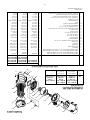
MODELS
JSAL180D JSAL210D
JSAL180E JSAL210E
JSAL15D JSAL180E JSAL210E
JSAL15E JSALS180E JSAL210F
Key No. JSALS15E JSAL180F JSALS210F
No. Part Description Used
15” Filter 18” Filter 21” Filter
1 Pump* (Models with -06, -09 suffix) 1 JWP Series JWP Series JWP Series
1 Pump** (All other suffixes) 1 JWP Series JWP Series JWP Series
1 Pump+ (“ABG” Series) 1 “ABG” Series “ABG” Series “ABG” Series
2 O-Ring 2 U9-226 U9-226 U9-226
3 Hose Assembly (Includes Key No. 2) 1 24203-0036 24203-0033 24203-0034
4A Hose Adapter 2 11201-0002 11201-0002 11201-0002
4B Sight Glass 1 14962-0012 14962-0012 14962-0012
5 Multiport Valve** (Includes Key Nos. 6, 7 and 16) 1 WC112-148A WC112-148A WC112-148A
6 O-Ring, Tank Flange 1 U9-369 U9-369 U9-369
7 V-Clamp with Knob 1 WC119-87A WC119-87A WC119-87A
8 Pedestal Platform 1 24201-0055P 24201-0055P 24201-0055P
9 Drain Cap 1 14965-0025 14965-0025 14965-0025
10 O-Ring, Drain Cap 1 U9-371 U9-371 U9-371
11 Drain Lateral Tube 1 24201-0058 24201-0058 24201-0058
12 O-Ring, Lateral Tube 1 U9-370 U9-370 U9-370
13 Lateral Tube 8 24600-0003 24600-0003 24600-0003
14 Collector Hub Assembly 1 24200-0110 WC137-516P WC137-517P
15 Tank Assembly 1 24200-0100 24201-0100 24203-0100
16 Clamp Knob 1 WC36-22 WC36-22 WC36-22
17 Filter Tank Ass’y (Includes Key Nos. 8 thru 15) 1 24200-9100S 24201-9100S 24203-9100S
18 Washer 1/4" 2 U43-60SS U43-60SS U43-60SS
19 Screw 1/4-20x3/4" Lg. 2 U30-52SS U30-52SS U30-52SS
• Hose, 1-1/2" x 6’ Lg.*** 2 34055-7038 34055-7038 34055-7038
• Sand Shield 1 24201-0043 24201-0043 24201-0043
• Nameplate Decal 1 32155-4115A 32155-4115B 32155-4115C
• Clamp Decal, Warning 1 32165-4030 32165-4030 32165-4030
• Information Decal 1 32155-4112 32155-4112 32155-4112
• Not illustrated. *See Page 15. **See Page 16.
*** Models JSAL15D-59, JSAL180F-05, and JSAL210F-05 do not include 6’ hose.
+ Model JSALS15E uses an “ABG” series pump.
7
8
17
1
6
1
5
14
13
12
11
10
9
1
3
2
18
19
4
A
4B
5
6
1277 0994
Repair Parts List - Filter

15
• Not illustrated.
* Not available separately.
Model Motor No. Impeller No.
No. HP (Key No. 6) (Key No. 11)
Single Speed
JWPA5DC-2A3 3/4 AS901DL C105-228PWBS
JWPA5EC-2A3 1 AS901EL C105-228PWS
JWPS5FC-2A3 1-1/2SPL AS901SFL C105-228PWS
Dual Speed
17290-J1002 1 – 1/6 17182-0090 C105-228PWS
Model Cord & Cap Assembly
No. HP (Key No. 2)
JWPA5DC-2A3 3/4 17190-0026-S
JWPA5EC-2A3 1 17190-0026-S
JWPS5FC-2A3 1-1/2SPL 17190-0026-S
Dual Speed
17290-J1002 1 – 1/6 17190-0028-S
Parts are common to all models listed except as noted;
Key Nos. 2, Cord & Cap Assembly; 6, Motor; and 11,
Impeller, are listed below.
Order PKG. 115 for 5" Trap complete (includes
Key Nos. 17 through 25).
1
2
3
4
5
6
7
8
9
10
1
3
13B
13A
12
11
14
20
21
22
23
19
24
2
5
26
9
A
15
1
6
17
18
19
NOTICE:
AT23 series models use the
same front plate and
seal plate as other models;
however, they are rotated
90° counter-clockwise
when installed.
782 0294
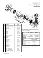
Key Part
No. Description Qty. Number
1 End Cap Screw 3 37337-0085
2 End Cap and Cord Assembly 1 Chart at Right
3 Toggle Switch 1 16920-0511
4 Toggle Switch Boot 1 32800-0107
5 Baffle Ring 1 17290-0004
6 Motor 1 Chart at Right
7 Motor Cover 1 17190-0021
8 Slinger 1 17351-0009
9 Seal Plate 1 C1-260P
10 Shaft Seal 1 37400-0027S
11 Impeller 1 Chart at Right
12 O-Ring 1 U9-357
13 Front Plate (Includes
Key Nos. 13A, 13B, 19) 1 C101-272PS
13A Wear Ring* 1
13B Pipe Plug 2 WC78-40T
14 Cap Screw 4 30387-0005
15 Trap Lid 1 C3-139P1
16 Trap Lid Gasket 1 U9-229
17 Trap Basket 1 C108-33P
18 Trap Body 1 C153-53P
19 Drain Plug w/O-Ring 2 U178-920P
20 Cap Screw 4 U30-64SS
21 Lock Washer 4 U43-11SS
22 Plain Washer 4 U43-41SS
23 Trap Outlet Gasket 1 C20-123
24 Mounting Foot 1 17190-0023
25 Plain Washer 4 U43-117SS
26 Cap Screw 4 U30-52SS
• Nameplate 1 32155-4073
• Decal – GFCI Required 1 U27-558
• Decal – Insulated Wet End 1 U27-584
• Tag – Do Not Use Pipe Dope 1 61002-0002
• Tag – Caution 1 61002-0004
REPAIR PARTS LIST
POOL PUMPS
3/4 thru 1-1/2 HP Single Speed
1 Hp Dual Speed

16
6
8
9
10
11
12
13A
13
14
19
21
22
23
1
3B
15
17
16
1
8
19
20
3
81 1293
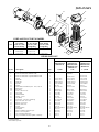
Model Number
Key No. Description Qty. 3/4 HP 1 HP 1- 1/2 HP
6 Motor 115/60H/1Ph (Without Cord) 1 AS920DLL AS920ELL AS920FLL
6 Motor 230/60H/1Ph (Without Cord) 1 – AS923EL –
6 Motor 115/60H/1Ph 1-Speed (Without Cord) 1 – – 62003-2031
6 Motor 115/60H/1Ph 2-Speed (Without Cord) 1 – 62003-2021 62003-2032
8 Slinger 1 17351-0009 17351-0009 17351-0009
9 Seal Plate 1 17301-0150 17301-0150 17301-0150
10 Shaft Seal 1 37400-0027S 37400-0027S 37400-0027S
11 Impeller 1 C105-228PH C105-228PG C105-228PG
12 O-Ring 1 U9-357 U9-357 U9-357
13 Front Plate (Includes Key Nos. 13A, 13B, 19) 1 C101-272PS C101-272PS C101-272PS
13A Wear Ring* 1
13B Pipe Plug 2 WC78-40T WC78-40T WC78-40T
14 Screw, 1/4-20x1-3/4 6 30787-0005 30787-0005 30787-0005
15 Trap Cover 1 C3-139P1 C3-139P1 C3-139P1
16 Strainer Basket 1 C108-33P C108-33P C108-33P
17 O-Ring - Cover 1 U9-229 U9-229 U9-229
18 Trap Body 1 C153-53P1 C153-53P1 C153-53P1
19 Drain Plug - 1/4" NPT (w/O-Ring) 2 U178-920P U178-920P U178-920P
20 Capscrew 5/16-18x1-1/4" 4 U30-64SS U30-64SS U30-64SS
21 Washer, Lock 5/16" 4 U43-11SS U43-11SS U43-11SS
22 Washer, Flat 5/16" 4 U43-41SS U43-41SS U43-41SS
23 Gasket 1 C20-123 C20-123 C20-123
• Cord Assembly 1 See Chart Above See Chart Above See Chart Above
• Nameplate 1 U33-155 U33-155 U33-155
• Decal “Tested for Pools & Spas” 1 U27-635 U37-635 U27-635
• Decal - GFCI required 1 U27-558 U27-558 U27-558
• Tag - bonding instructions 1 C63-12 C63-12 C63-12
• Tag - CAUTION Securely Tighten…Warning… 1 C63-13 C63-13 C63-13
REPAIR PARTS LIST
JWPA PUMPS
• Not illustrated.
* Not available separately.
-2A2 Models
-2A1 Models 2A, -A2U Models -2A4U Models
HP Cord Ass’y with Cord Ass’y with Cord Ass’y with
Twist-lock Plug Straight Plug Straight Plug
3/4 31953-0101 U117-1117 –
1 31953-0101 U117-1117 –
1-1/2 31953-0101 U117-1118 31953-0116
CORD AND PLUG PART NUMBERS
JWPA5DL-2A1
JWPA5DL-2A2
JWPS5EL-A2
JWPA5EL-2A1
JWPA5EL-2A2
JWPA5E-230A2
JWPA5YFL-A2U
JWPS5FL-A2
JWPA5FL-2A1
JWPA5FL-2A2
JWPAS5F-2A4U
JWPS5FL-A2

17
ABG PUMPS
• Not illustrated.
* Included with top discharge pumps only.
8
9
1
2
6
7
4
3
10
11
12
5
D
O N
O
T
O
V
E
R
T
IG
HT
E
N
13
14
15
3345 1198
Key Part Part
No. Description Qty. No.
1 Motor 1 Chart at Right
2 Slinger 1 C69-2
3 Seal Plate 1 17500-0001
4 Seal Plate O-Ring 1 35505-1438
5 Shaft Seal 1 U109-358SS
6 Impeller 1 Chart at Right
7 Floating Wear Ring 1 17500-0004
8 Trap Body 1 17500-0002
9 Trap Lid 1 17500-0003
10 Trap Lid O-Ring 1 35505-1437
11 Trap Basket 1 17350-0100
12 Drain Plug 1 U178-920P
13 Hex Head Bolt,
1/4-20x1-3/4" 4 30787-0005
14 Hex Nut 4 35402-0071
15 Cord 1 Chart at Right
• Hardware Kit*
(2 Bolts, 2 Washers) 1 17290-0001
• Nameplate 1 U33-155
• Warning Tag 1 61002-0013
• Caution Tag 1 C63-12
• Decal - “GFCI Required” 1 U27-558
Parts are common to all models listed except as noted:
Key Nos. 1, Motor; 6, Impeller; and 15 Cord are listed below.
For complete suction trap order Pkg. 115.
Motor No. Impeller No. Cord No.
Model No. HP Key No. 1 Key No. 6 Key No. 15
115 Volt/1-Speed, Top Discharge
ABG4C-3A4 1/2 62003-2034 17301-0114 31953-0116
ABG4C7-3A4 1/2 62003-2034 17301-0114 31953-0116
ABG4DL-2A1 3/4 AS920DLL 17301-0113 31953-0101
ABG4D-2A4 3/4 AS920DLL 17301-0113 31953-0116
ABGS4D-3A4 3/4 62003-2035 17301-0114 31953-0116
ABGS4DL-A2 3/4 62003-2035 17301-0114 U117-1117
ABGS4EL-A2 1 AS920DLL 17301-0113 U117-1117
ABG4EL-2A1 1 AS920ELL 17301-0112 31953-0101
ABG4EL-2A2 1 AS920ELL 17301-0112 U117-1117
ABG4E-2A4 1 AS920ELL 17301-0112 31953-0116
ABG4E-2A4SP 1 AS920ELL 17301-0112 31953-0116
ABGS4E-3A4 1 62003-2037 17301-0113 31953-0116
ABG4FL-2A1 1-1/2 AS920FLL 17301-0111 31953-0101
ABGS4FL-A2 1-1/2 62003-2031 17301-0112 U117-1117
ABGS4F-2A4 1-1/2 62003-2031 17301-0112 31953-0116
115 Volt/1-Speed, Side Discharge
ABG4D7L-2A1 3/4 AS920DLL 17301-0113 31953-0101
ABG4D7-2A4 3/4 AS920DLL 17301-0113 31953-0116
ABGS4D7-3A4 3/4 62003-2035 17301-0114 31953-0116
ABG4E7L-2A1 1 AS920ELL 17301-0112 31953-0101
ABG4E7L-2A2 1 AS920ELL 17301-0112 U117-1117
ABG4E7-2A4 1 AS920ELL 17301-0112 31953-0116
ABG4E7-2A4SP 1 AS920ELL 17301-0116 31953-0116
ABG4E7-2A4SPH 1 AS920ELL 17301-0113 31953-0116
ABGS4E7-3A4 1 62003-2037 17301-0113 31953-0116
ABG4F7L-2A1 1-1/2 AS920FLL 17301-0011 31953-0101
ABGS4F7-2A4 1-1/2 62003-2031 17301-0112 31953-0116
115 Volt/2-Speed, Top Discharge
ABG4YD-A1 3/4 AS900DLL-Y 17301-0113 31953-0101
ABG4YD-A2 3/4 AS900DLL-Y 17301-0113 U117-1117
ABG4YE-2A4 1 62003-2021 17301-0112 31953-0116
ABG4YF-A2 1-1/2 62003-2032 17301-0111 U117-1117
ABGS4YG-A1 2 62003-2023 17301-0111 31953-0101
ABGS4YG-A2 2 62003-2023 17301-0111 U117-1117
115 Volt/2-Speed, Side Discharge
ABG4YE7-2A4 1 62003-2021 17301-0112 31953-0116
ABGS4YE7-A1 1 AS900DLL-Y 17301-0113 31953-0101
ABGS4YE7-A2 1 AS900DLL-Y 17301-0113 U117-1117
ABG4YF7-A2 1-1/2 62003-2032 17301-0111 U117-1117
ABGS4YF7-A1 1-1/2 62001-1035 17301-0112 31953-0101
ABGS4YF7-A2 1-1/2 62001-1035 17301-0112 U117-1117

18
R
E
C
I
R
C
U
L
A
T
E
B
A
C
K
W
A
S
H
C
L
O
S
E
D
W
I
N
T
E
R
I
Z
E
W
A
S
T
E
F
I
L
T
E
R
R
I
N
S
E
1
2
3
4
5
6
7
8
9A
10
11
9B
12
13
14
15
16
Aquatools
.WATERFORD, WI.
53185
USA
762 0294
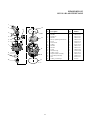
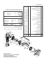
Key Part
No. Description Qty. Number
1
Decal, Valve Handle 1 32145-4016
2 Handle 1 14962-0032
3 Dowel Pin 1 35857-0021
4 Washer 1 14965-0007
5 Decal, Operating Instructions 1 14965-0020
6 Screw 7 37067-0714
7 Valve Cover 1 14965-0011
8 O-Ring 1 35505-1228
9A Washer 2 14965-0007
9B Washer 1 14965-0007
10 Spring 1 14965-0006
11 Pressure Gage 1 15060-0000T
12 O-Ring, Cover 1 35505-1275
13 Plug & Gasket Assembly 1 14965-0028
14 Valve Body Assembly 1 14965-0013
15 Nut 7 35407-0071
16 O-Ring, Tank Flange 1 U9-369
REPAIR PARTS LIST
WC112-148A MULTIPORT VALVE

19

CREATE A RECORD OF YOUR WARRANTY AT STA-RITE:
• Complete a warranty registration at www.staritepool.com by clicking on “Register Products” and selecting Sta-Rite Pool
OR
• Complete bottom portion completely and mail within 10 days of installation to Sta-Rite, Attn.: Pool Warranty Dept., 293 Wright St., Delavan , WI 53115
Warranty Registration Card
Name
Address
City State Zip
Installation (or Purchase) Date
Product Purchased
Model Number
■■ New installation ■■ Replacement
Years pool has been in service ■■ less than 1 ■■ 1-3 ■■ 3-5 ■■ 5-10
This product was purchased from:
Company name
Address
City State Zip
STA-RITE LIMITED WARRANTY
For technical information about this product, contact the installer or call Sta-Rite at 262-728-9181.
Visit www.staritepool.com
• for more information about Sta-Rite products listed above
• to locate a Sta-Rite dealer near you
Product Specific Warranties
(from date of installation)
Product Limited
Family Warranty Exceptions
Filters 1 Year System 3 Tank Bodies - 10 Yrs
Filter Valves 1 Year
Pumps 1 Year
Heaters 2 Years *Commercial Application - 1 Yr
Controls 1 Year
Above Ground Systems 1 Year
Lights and Niches 1 Year Lamps and Bulbs - 90 Days
White Goods 1 Year
Maintenance Equipment 90 Days
Drainer/Utility Pumps 90 Days
Replacement Parts 90 Days
Cleaners: Lil Shark 1 Year
Cleaners: Calypso 1 Year
Cleaners: Pool Shark 2 Years Footpad and Seal Flaps - 1 Yr
Cleaners: Great White 2 Years
* Commercial and multi-family application.
Retain this warranty certificate in a
safe and convenient location for your records.
Pumps, filters, skimmers, underwater lights (excluding bulbs), ac-
c
essories and fittings manufactured by Sta-Rite are warranted to
be free of defects in material and/or workmanship for one (1) year
from the original date of installation.
The foregoing warranties relate to the original consumer purchaser
(“Purchaser”) only. Sta-Rite Industries shall have the option to re-
pair or replace the defective product, at its sole discretion.
Purchasers must pay all labor and shipping charges necessary to
replace the product covered by this warranty. Requests for war-
ranty service must be made through the installing dealer. This war-
ranty shall not apply to any product that has been subject to
negligence, misapplication, improper installation or maintenance,
or other circumstances which are not in Sta-Rite’s direct control.
F
ailure to have product installed by a professional in compliance
with local codes will void any and all manufacturers warranty.
This warranty sets forth Sta-Rite’s obligation and Purchaser’s ex-
clusive remedy for defective products.
STA-RITE SHALL NOT BE LIABLE FOR ANY CONSEQUENTIAL,
INCIDENTAL OR CONTINGENT DAMAGES WHATSOEVER.
THE FOREGOING WARRANTIES ARE EXCLUSIVE AND IN
LIEU OF ALL OTHER EXPRESS WARRANTIES. IMPLIED WAR-
RANTIES, INCLUDING BUT NOT LIMITED TO THE IMPLIED
WARRANTIES OF MERCHANTABILITY AND FITNESS FOR A
PARTICULAR PURPOSE, SHALL NOT EXTEND BEYOND THE
DURATION OF THE APPLICABLE EXPRESS WARRANTIES
PROVIDED HEREIN.
Some states do not allow the exclusion or limitation of incidental or
consequential damages or limitations on how long an implied war-
ranty lasts, so the above limitations or exclusion may not apply to
you. This warranty gives you specific legal rights and you may also
have other rights which vary from state to state.
Supersedes all previous publications.
S4877PS (Rev. 7/21/04)
La page est en cours de chargement...
La page est en cours de chargement...
La page est en cours de chargement...
La page est en cours de chargement...
La page est en cours de chargement...
La page est en cours de chargement...
La page est en cours de chargement...
La page est en cours de chargement...
La page est en cours de chargement...
La page est en cours de chargement...
La page est en cours de chargement...
La page est en cours de chargement...
La page est en cours de chargement...
La page est en cours de chargement...
La page est en cours de chargement...
La page est en cours de chargement...
La page est en cours de chargement...
La page est en cours de chargement...
La page est en cours de chargement...
La page est en cours de chargement...
-
 1
1
-
 2
2
-
 3
3
-
 4
4
-
 5
5
-
 6
6
-
 7
7
-
 8
8
-
 9
9
-
 10
10
-
 11
11
-
 12
12
-
 13
13
-
 14
14
-
 15
15
-
 16
16
-
 17
17
-
 18
18
-
 19
19
-
 20
20
-
 21
21
-
 22
22
-
 23
23
-
 24
24
-
 25
25
-
 26
26
-
 27
27
-
 28
28
-
 29
29
-
 30
30
-
 31
31
-
 32
32
-
 33
33
-
 34
34
-
 35
35
-
 36
36
-
 37
37
-
 38
38
-
 39
39
-
 40
40


Waterford JSAL210D Le manuel du propriétaire
- Catégorie
- Accessoires de piscine hors terre
- Taper
- Le manuel du propriétaire
dans d''autres langues
- English: Waterford JSAL210D Owner's manual
Autres documents
-
Pulsar 79214 1 HP Le manuel du propriétaire
-
Pentair CRISTAL-FLO II Mode d'emploi
-
-
Flotec FPT20515 Le manuel du propriétaire
-
-
Pentair System 2 PLM300 Le manuel du propriétaire
-
ELICA NikolaTesla Alpha BL/A/78 Cooker Hoods Manuel utilisateur
-
 FLOTIDE MFV17 Filter S Max Series Top Mount Sand Filter Manuel utilisateur
-
Blue Wave NE6161 Manuel utilisateur
-
Bluewave NE4488 Manuel utilisateur
