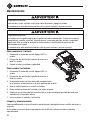
Greenlee DM-860A Manuel utilisateur
- Catégorie
- Mesure, test
- Taper
- Manuel utilisateur
Ce manuel convient également à

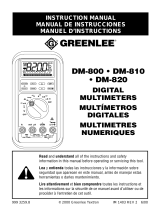
INSTRUCTION MANUAL
MANUAL DE INSTRUCCIONES
MANUEL D’INSTRUCTIONS
Read and understand all of the instructions and safety information in this
manual before operating or servicing this tool.
Lea y entienda todas las instrucciones y la información sobre seguridad
que aparecen en este manual, antes de manejar estas herramientas o
darles mantenimiento.
Lire attentivement et bien comprendre toutes les instructions et les
informations sur la sécurité de ce manuel avant d’utiliser ou de procéder à
l’entretien de cet outil.
Register this product at www.greenlee.com / Registre este producto en www.greenlee.com
Enregistrez votre produit en ligne, www.greenlee.com
DM-860A
Digital
Multimeter
Multímetro
digital
Multimètre
numérique
52056270 REV 2 © 2019 Greenlee Tools, Inc. 9/19

2
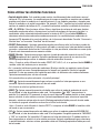
Description
The Greenlee DM-860A Digital Multimeter is a hand-held testing device with the following measure-
ment capabilities: AC and DC voltage, AC and DC current, percent of loop current, two channels of
temperature (K-type thermocouples), frequency, duty cycle, resistance, conductance, and capacitance.
It also checks diodes and verifies continuity.
The DM-860A features a bar graph display that responds more quickly than the numeric display—
useful for detecting faulty contacts, potentiometer clicks, and signal spikes. An optional optically
isolated computer interface with software facilitates the recording of readings from the meter to a
computer.
Other specialized functions and capabilities include:
• Dual display shows two measurements, such as AC voltage and frequency, at the same time.
• Beep-Jack™ audible warning alerts the user with a beep and an error message on the LCD if the
test lead is plugged into the mAµA or A input terminal while the selector switch is not in the mAµA
or A position.
• AC bandwidth to 100 kHz for voltage or 20 kHz for current.
• MAX/MIN function which stores the maximum, minimum, and average.
• Crest capture mode to capture voltage or current signal peaks.
• Selectable between 50,000 or 500,000 counts resolution when measuring DC voltage.
• Relative zero mode.
• Automatic or manual ranging.
• Intelligent automatic power off.
• Backlighted LCD for reading in dim conditions.
Safety
Safety is essential in the use and maintenance of Greenlee tools and equipment. This instruction
manual and any markings on the tool provide information for avoiding hazards and unsafe practices
related to the use of this tool. Observe all of the safety information provided.
Purpose of This Manual
This instruction manual is intended to familiarize all personnel with the safe operation and maintenance
procedures for the Greenlee DM-860A Digital Multimeter.
Keep this manual available to all personnel. Replacement manuals are available upon request at no
charge at www.greenlee.com.
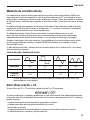
Do not discard this product or throw away!
For recycling information, go to www.greenlee.com.

DM-860A
3
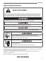
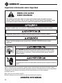
SAFETY ALERT SYMBOL
This symbol is used to call your attention to hazards or unsafe practices which could result in an
injury or property damage. The signal word, defined below, indicates the severity of the hazard.
The message after the signal word provides information for preventing or avoiding the hazard.
Immediate hazards which, if not avoided, WILL result in severe injury or death.
Hazards which, if not avoided, COULD result in severe injury or death.
Hazards or unsafe practices which, if not avoided, MAY result in injury or property damage.
Read and understand this material before operating or servicing this
equipment. Failure to understand how to safely operate this tool could result in
an accident causing serious injury or death.
Electric shock hazard:
Contact with live circuits could result in severe injury or death.
Important Safety Information
All specifications are nominal and may change as design improvements occur. Greenlee Tools, Inc. shall not be liable
for damages resulting from misapplication or misuse of its products.
® Registered: The color green for electrical test instruments is a registered trademark of Greenlee Tools, Inc.
Beep-Jack is a trademark of BTC.
Microsoft and Windows are registered trademarks of Microsoft Corporation.
KEEP THIS MANUAL

4
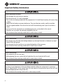
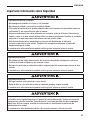
Important Safety Information
Electric shock and fire hazard:
• Do not expose this unit to rain or moisture.
• Do not use the unit if it is wet or damaged.
• Only use the test leads provided with the equipment or UL Listed Probe Assembly with same rating
or better.
• Inspect the test leads or accessory before use. They must be clean and dry, and the insulation
must be in good condition. Do not use the test lead if the contrasting inner layer of insulation is
visible.
• Use this unit for the manufacturer’s intended purpose only, as described in this manual.
Anyotheruse can impair the protection provided by the unit.
Failure to observe these warnings could result in severe injury or death.
Electric shock hazard:
• Do not apply more than the rated voltage between any two input terminals, or between any input
terminal and earth ground.
• Do not contact the test lead tips or any uninsulated portion of the accessory.
Failure to observe these warnings could result in severe injury or death.
Electric shock hazard:
• Do not operate with the case open.
• Before opening the case, remove the test leads from the circuit and shut off the unit.
Failure to observe these warnings could result in severe injury or death.
Electric shock hazard:
The fuses are an integral part of the overvoltage protection. When fuse replacement is necessary,
refer to “Specifications” for the correct type, size, and capacity. Using any other type of fuse will void
the overvoltage protection rating of the unit.
Failure to observe this warning could result in severe injury or death.

DM-860A
5
Important Safety Information
Electric shock hazard:
• Unless measuring voltage, current, or frequency, shut off and lock out power. Make sure that all
capacitors are discharged. Voltage must not be present.
• Set the selector and connect the test leads so that they correspond to the intended measurement.
Incorrect settings or connections can result in a blown fuse.
• Using this unit near equipment that generates electromagnetic interference can result in unstable
or inaccurate readings.
Failure to observe these warnings could result in severe injury or death.
Electric shock hazard:
Do not change the measurement function while the test leads are connected to a component or
circuit.
Failure to observe this precaution may result in injury and can damage the unit.
Electric shock hazard:
• Do not attempt to repair this unit. It contains no user-serviceable parts.
• Do not expose the unit to extremes in temperature or high humidity. Refer to “Specifications.”
Failure to observe these precautions may result in injury and can damage the unit.

6
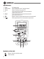
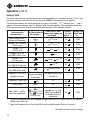
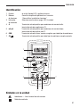
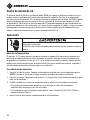
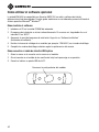
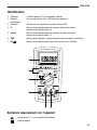
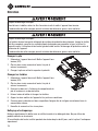
Identification
1. Display LCD and bar graph
2. Feature Buttons Refer to explanations under “Using the Features”
3. Selector Selects a function or turns power OFF
4. A Positive input terminal for high current measurements;
negative input terminal for T2
5. mA µA Positive input terminal for low current measurements;
positive input terminal for T2
6. COM Negative, common, or ground input terminal for all measurements
7. ΩV Positive input terminal for all measurements except current
1
3
2
4 7
5 6
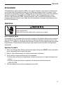
Symbols on the Unit
Warning—Read the instruction manual
Double insulation

DM-860A
7
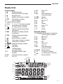
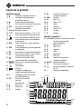
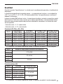
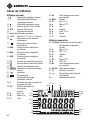
Primary Display
8.
Bar graph element
9. – Polarity indicator for bar graph
10. Bar graph scale
11. ∆ Relative zero function is enabled.
12. VFD VFD function is enabled.
13. – Polarity indicator
14. 8.8.8.8.88 Numeric display
15. T1-T2 T1, T2, or T1-T2 function is enabled.
16. AC measurement is selected.
17. DC measurement is selected.
18. MAX Maximum value being recorded
or displayed.
19. MIN Minimum value being recorded
or displayed.
20. AVG Average value being recorded
or displayed.
21. Record function is enabled.
22. Crest capture function is enabled.
23. Hold function is selected.
24. Automatic ranging is enabled.
25. Continuity
26. Low battery
27. } Overload symbol
(bar graph display)
28. 5 Bar graph maximum range
indicator
29. D% Duty cycle function is enabled.
30. k Kilo (10
3
)
31. M Mega (10
6
)
32. Ω Ohm
33. Hz Hertz (frequency in
cycles per second)
34. dBm Decibel
35. m Milli (10
-3
)
36. µ Micro (10
-6
)
37. V Volt
38. A Ampere
39. n Nano (10
-9
)
40. F Farad
41. S Siemen
Secondary Display
42. %4-20mA Industrial process control loop
current function is enabled.
43. µ Micro (10
-6
)
44. m Milli (10
-3
)
45. A Ampere
46. V Volt
47. M Mega (10
6
)
48. k Kilo (10
3
)
49. Hz Hertz (frequency in
cycles per second)
50. 8.8.8.8 Numeric display
51. T2 T2 function is enabled.
52. AC measurement is selected.
53. – Polarity indicator
Display Icons
24
21-23
18-20
16-17
15
12
11
10
8-9
13-14
47-49
43-46
42
29-41
27
28
2625
51-53
50

8
• Dual Digital Display: This meter can display two measurements, such as AC voltage and frequency,
at the same time. Display combinations are shown using large symbols to indicate the measurement
on the primary display and small, raised symbols to indicate the measurement on the secondary
display. For example, “VAC
Hz
” means the primary display contains the AC voltage measurement, and
the secondary display contains the frequency measurement.
• VFD ~V and VFD Hz: These functions use filtering and noise-rejection algorithms to make accurate
voltage and frequency measurements on most variable frequency drives. The voltage measure-
ment automatically selects the 500 volt range. Use the RANGE button to select other ranges only
when needed. The sensitivity for VFD frequency measurements depends on voltage range and input
frequency. Refer to “Frequency – Line Level” in the “Accuracy” section of this manual.
• SELECT: Press momentarily to toggle between functions, measurement modes, or display modes.
The last used setting becomes the default when that function is selected again. To change the
default, select a new setting. The setting will be stored in nonvolatile memory.
• RANGE: Press once to enter the manual ranging mode. The icon will disappear from the
display. Press repeatedly to step through the ranges. Press and hold to return to the automatic
ranging mode.
Note: When using CREST, REC, HOLD, or ∆ mode, pressing RANGE will cause the meter to exit that
mode.
• ∆: Finds the difference between two measurements. While taking a measurement, press ∆ to set the
display to zero. The ∆ icon will appear on the display. Take the second measurement. The value on
the display will be the difference between the two measurements. Press again to exit this mode.
This feature applies to the main display only.
• HOLD : Press momentarily to hold the present value on the display. Press again to exit this mode.
This feature does not affect the bar graph.
• CREST : Press momentarily to activate the crest recording mode.The input value is measured
every 1 ms in this mode. and “MAX” will appear on the display. The LCD will display the maximum
crest value. The meter will beep whenever the maximum or minimum is updated. Press repeatedly to
select the desired display: maximum or minimum crest value. Press and hold to exit this mode.
The automatic power off feature is disabled when using this function.
Note: When using the CREST function, pressing RANGE will cause the meter to exit this mode.
• REC : Press momentarily to activate the MAX/MIN/AVG recording mode. The input value is
measured every 50 ms in this mode. “MAX MIN” and “AVG” will appear on the display. The LCD will
display the actual input value. The meter will beep whenever the maximum or minimum is updated.
Press repeatedly to select the desired display: maximum, minimum, average, or actual input. Press
and hold to exit this mode.
The automatic power off feature is disabled when using this function.
Note: When using the REC function, pressing RANGE will cause the meter to exit this mode.
• : Press and hold until backlight illuminates. Press and hold again to turn off. The backlight
automatically turns off after approximately 30 seconds to extend battery life.
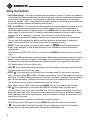
Using the Features

DM-860A
9
Using the Features (cont’d)
• dBm-Ω: The reference impedance is displayed for 1 second after selecting the dBm function.
Momentarily press dBm-Ω to change the reference impedance. Refer to the “Specifications” section
for the available values.
Note: This is an AC voltage measurement calculated according to the formula
dBm = 20 x log (measured voltage / reference voltage
The reference voltage is the voltage that causes 1 mW of power to be dissipated in the selected
reference impedance.
• T1-T2: Press momentarily to select the desired temperature display: T1, T2, T1
T2
, or T1-T2
T2
.
• 500000: Press and hold to toggle between 50,000 counts fast mode and the 500,000 counts high
resolution mode for DC voltage measurements.
• Intelligent Automatic Power Off (APO): To extend battery life, the meter shuts itself off after
approximately 17 minutes of inactivity. Inactivity occurs when buttons are not pressed or the selector
is not turned. The meter will not enter APO when there are significant readings of over 10% of the
range or non-OL readings for resistance and continuity. To restore power, press SELECT, RANGE, ∆,
or HOLD or turn the selector to OFF and back on again. To disable this feature, press SELECT while
turning the meter on.
• Disabling the Beeper: Hold down the RANGE button while turning the meter on to temporarily
disable the beeper feature. Turn the selector to OFF and then back on to enable the beeper.
• Hz: Frequency can be measured in most voltage and current settings of the selector. Press SELECT
until “Hz” appears in the primary or secondary display, as desired. The sensitivity of the Line Level
Frequency function varies with measurement range. Refer to “Specifications.” Auto-ranging mea-
surements usually set the best trigger level. If the frequency reading becomes unstable or is blank,
press the RANGE button to select another trigger level.
• %4-20mA: This calculated value is one of three available options for the secondary display when
measuring DC milliamps. It is useful for 4-20 mA industrial process control loop applications. A
reading of 4 mA on the primary display gives a 0% reading on the secondary display, 12 mA gives
50%, 20 mA gives 100%, etc.

10
AC Measurement
AC measurements are usually displayed as RMS (root mean square) values. The RMS value is equal to
the value of a DC waveform, which would deliver the same power if it replaced the time-varying wave-
form. Two AC measurement methods are average-responding RMS calibrated and true RMS-reading.
The average-responding RMS calibrated method takes the average value of the input signal after full
wave rectification, multiplies it by 1.11, and displays the result. This method is accurate if the input
signal is a pure sine wave.
The true RMS-reading method uses internal circuitry to read the true RMS value. This method is accu-
rate, within the specified crest factor limitations, whether the input signal is a pure sine wave, square
wave, triangle wave, half wave, or signal with harmonics. The ability to read true RMS provides much
more measurement versatility. The Greenlee DM-860A is a true RMS meter.
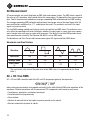
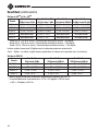
The Waveforms and Crest Factors table shows some typical AC signals and their RMS values.
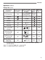
Waveforms and Crest Factors
Waveform
RMS Value 100 100 100 100
Average Value 90 100 87 64
Crest Factor*
(x)
1.414 1 1.73 2
* The crest factor is the ratio of the peak value to the RMS value; it is represented by the Greek
letter x.
AC + DC True RMS
AC + DC true RMS calculates both of the AC and DC components given by the expression
when making measurements and responds accurately to the total effective RMS value regardless of the
waveform. Distorted waveforms with the presence of DC components and harmonics may cause:
• Transformers, generators, and motors to overheat
• Circuit breakers to trip prematurely
• Fuses to blow
• Neutrals to overheat due to the triplen harmonics present on the neutral
• Bus bars and electrical panels to vibrate

DM-860A
11
AC Bandwith
AC bandwidth of a digital multimeter (DMM) is the range of frequencies over which AC measurements
can be made within the specified accuracy. It is the frequency response of the AC functions—not of
the frequency measurement functions. A DMM cannot accurately measure the AC value with frequency
spectrums beyond the AC bandwidth of the DMM. Therefore, wide AC bandwidth plays an impor-
tant role in high performance DMMs. Complex waveforms, noise, and distorted waveforms contain
frequency components that are much higher than the fundamental; for example, high frequency noise
on a 50/60 Hz power line.
Operation
Electric shock hazard:
Contact with live circuits could result in severe injury or death.
Self-Diagnostic Mode
The message “rE-O” may appear when the meter is turned on. This indicates that the meter is perform-
ing a routine self-diagnostic. Do not turn the meter off. Allow the diagnostic procedure to finish. If the
message “C_Er” appears on the display when the meter is turned on, some ranges may be well outside
of specification. To avoid incorrect measurements, stop using the meter and return it to Greenlee for
recalibration.
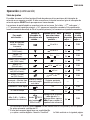
Operating Procedure
1. Refer to the Settings Table. Set the selector to the proper setting, press SELECT (when instructed to
do so), and connect the test leads to the meter.
2. Refer to “Typical Measurements” for specific measurement instructions.
3. Test the unit on a known functioning circuit or component.
• If the unit does not function as expected on a known functioning circuit, replace the battery and/
or fuses.
• If the unit still does not function as expected, call Greenlee for technical assistance
at 800-435-0786.
4. Take the reading from the circuit or component to be tested.

12
Operation (cont’d)
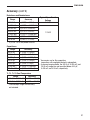
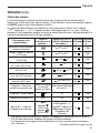
Settings Table
The meter stores the last used function of each selector position in its nonvolatile memory. If this is not
the correct function when you turn the selector, press SELECT until the desired icon appears.
The dual display options are shown along with the icons. In the table, “~V
Hz
” indicates that “~” and “V”
appear in the primary display, and “Hz” appears in the secondary display. This combination shows the
AC voltage measurement in the primary display and frequency in the secondary display.
To measure this
characteristic …
Set the selector to
this symbol…
Press SELECT until
these icons appear on
the display …
Connect
the red
lead to…
Connect the
black lead
to …
Variable Speed Drive—
Voltage and Frequency
V
Hz
or Hz
~V
ΩV
COM
Voltage—AC TrueRMS
(1000 V max)
V
Hz
or Hz
~V
ΩV
COM
*Voltage—DC
(1000 V max)
V or V
~V
ΩV
COM
Voltage—AC + DC
True RMS (1000 V max)
V
~V
ΩV
COM
Voltage—DC
(500 mV max)
mV or mV
~mV
ΩV
COM
Voltage—AC + DC
True RMS (500 mV max)
mV
~mV
ΩV
COM
Voltage—AC
True RMS (500 V max)
mV
Hz
or Hz
~mV
ΩV
COM
Frequency—Line Level
Voltage or Current
Set for voltage or
current according
to this table.
Any display option that
includes Hz
— —
**Frequency—Logic Level
Hz
Hz
ΩV
COM
% Duty Cycle D% D%
ΩV
COM
dBm (0 dB = 1 mW in
reference impedance)
dBm
( function 1000 V
max;
function
500 mV max.)
Reference impedance
and dBm for 1 s, then
dBm
Hz
(press dBm-Ω
to change reference
impedance)
ΩV
COM
* For precise measurements, press 500000 to toggle between 50,000 counts and 500,000 counts.
Applies to DC volts only.
** Logic level frequency has a fixed sensitivity and is for digital signals. Refer to “Accuracy”.
This table continues on the next page.

DM-860A
13
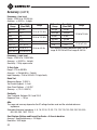
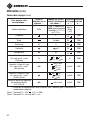
Settings Table (cont’d)
To measure this
characteristic …
Set the selector to
this symbol…
Press SELECT until
these icons appear on
the display …
Connect
the red
lead to…
Connect the
black lead
to …
Dual Temperature T1T2
°C or °F (press RANGE
for display options T1,
T2, T1
T2
or T1-T2
T2
)
See Notes
1 and 2
—
†Capacitance F
ΩV
COM
Diode V and diod
ΩV
COM
Resistance Ω Ω
ΩV
COM
Continuity
and Ω
ΩV
COM
Conductance nS nS
ΩV
COM
Current—AC, DC, or
AC + DC True RMS
(10 A max)
A
A, A
~A,
A
~A,
or A
Hz
A COM
Current—AC, DC, or
AC + DC True RMS
(600 mA max)
mA
mA
%4-20mA,
mA
~mA,
mA
~mA,
or mA
Hz
mA µA COM
Current—AC, DC, or
AC + DC True RMS
(6000 µA max)
µA
µA, µA
~µA,
µA
~µA,
or µA
Hz
mA µA COM
Industrial Process Control
Loop Current
% 4 to 20 mA
mA
mA
%4-20mA
mA µA COM
† Discharge capacitor before measurement. Refer to “Typical Measurements” regarding
polarized capacitors.
Note 1: T1+ connects to ΩV , and T1– connects to COM.
Note 2: T2+ connects to mA µA, and T2– connects to A.
Operation (cont’d)

14
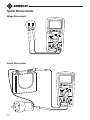
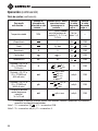
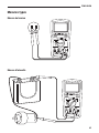
Typical Measurements
Voltage Measurement
Current Measurement

DM-860A
15
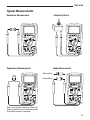
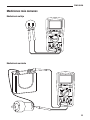
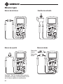
Typical Measurements
Continuity Check
Capacitance Measurement Diode Measurement
Resistance Measurement
Reverse Bias
Forward Bias
Note: For polarized capacitors, attach red
probe to positive terminal and black probe
to negative terminal of capacitor.

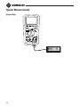
16
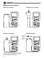
Typical Measurements
Temperature

DM-860A
17
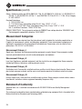
Using the Optional Software
The DM-860A is compatible with Greenlee DMSC-9U, an optically isolated computer interface cable
and software. It allows measurements to be logged to a personal computer using the Microsoft
®
Windows
®
operating system.
Installing the Software
1. Insert the CD into the computer’s CDROM drive.
2. The installation program should launch automatically. If it does not, double click on the CD icon in
“My Computer.”
3. The installation program menu will appear. Click on “Software Installation.”
4. Type your meter’s catalog number (for example, “DM-860A”) in the dialog box.
5. Complete the remaining dialog boxes according to user preferences.
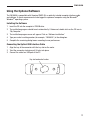
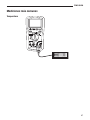
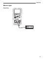
Connecting the Optical USB Interface Cable
1. Align the key of the connector with the key slot on the meter.
2. Twist the connector clockwise until it locks into place.
3. Connect the cable to a USB port of the PC.
Key slot on back of meter

18
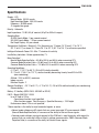
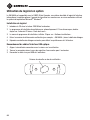
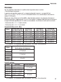
Accuracy
Refer to the “Specifications” section for operating conditions and temperature coefficient.
Accuracy is specified as follows: ± (a percentage of the reading + a fixed amount) at 23 °C ± 5 °C
(73.4 °F ± 9 °F), 0% to 75% relative humidity. Specifications are for 50,000 counts mode.
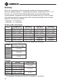
True RMS Readings: Voltage and current accuracies are specified from 5% to 100% of the range
unless otherwise specified. Frequency must be within the specified bandwidth for non-sinusoidal
waveforms. Crest factors are as follows:
• Crest factor < 2.1:1 at full scale
• Crest factor < 4.2:1 at half scale
AC, DC
AC
, and AC + DC
AC
Current
Range
Accuracy at DC
and 50 Hz to 60 Hz
Accuracy at
40 Hz to 1 kHz
Accuracy at
1kHz to 20 kHz
Accuracy at
20 kHz to 100 kHz
500.00 µA ± (0.5% + 0.5 µA) ± (0.7% + 0.5 µA) ± (2.0% + 0.5 µA) ± (5.0% + 0.5 µA)
5000.0 µA ± (0.5% + 5.0 µA) ± (0.7% + 5.0 µA) ± (2.0% + 5.0 µA) ± (5.0% + 5.0 µA)
50.000 mA ± (0.5% + 0.05 mA) ± (0.7% + 0.05 mA) ± (2.0% + 0.05 mA) ± (5.0% + 0.05 mA)
500.00 mA ± (0.5% + 0.5 mA) ± (0.7% + 0.5 mA) ± (2.0% + 0.5 mA) ± (5.0% + 0.5 mA)
5.0000 A ± (0.5% + 0.005 A) ± (0.7% + 0.005 A) Unspecified Unspecified
10.000 A* ± (0.5% + 0.05 A) ± (0.7% + 0.05 A) Unspecified Unspecified
*
10 A continuous; 20 A maximum (Duty Cycle: 30 seconds on, 5 minutes off).
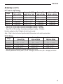
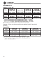
Range
Burden Voltage
(all frequency ranges)
500.00 µA
0.15 mV/µA
5000.0 µA
50.000 mA
3.3 mV/mA
500.00 mA
5.0000 A
45 mV/A
10.000 A
DC Current
Range Accuracy Burden Voltage
500.00 µA ± (0.15% + 0.2 µA)
0.15 mV/µA
5000.0 µA ± (0.1% + 2.0 µA)
50.000 mA ± (0.15% + 0.02 mA)
3.3 mV/mA
500.00 mA ± (0.15% + 0.3 mA)
5.0000 A ± (0.5% + 0.002 A)
45 mV/A
10.000 A* ± (0.5% + 0.02 A)
*
10 A continuous; 20 A maximum (Duty Cycle: 30 seconds on, 5 minutes off).

DM-860A
19
Accuracy (cont’d)
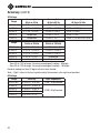
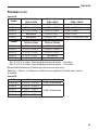
DC
AC
and AC + DC
AC
Voltage
Range
Accuracy* at
20 Hz to 45 Hz
Accuracy* at DC
and 45 Hz to 1 kHz
Accuracy* at
1 kHz to 20 kHz
Accuracy* at
20 kHz to 40 kHz
500.00 mV ± (1.5% + 0.4 mV) ± (0.5% + 0.4 mV) ± (1.0% + 0.4 mV) ± (3.5% + 0.4 mV)**
5.0000 V ± (1.5% + 0.004 V) ± (0.5% + 0.008 V) ± (1.2% + 0.004 V) ± (4.0% + 0.004 V)**
50.000 V ± (1.5% + 0.04 V) ± (0.5% + 0.08 V) ± (1.2% + 0.04 V) ± (4.0% + 0.04 V)**
500.00 V Unspecified ± (0.5% + 0.8 V) Unspecified Unspecified
1000.0 V Unspecified ± (0.5% + 8 V) Unspecified Unspecified
*
From 5% to 10% of range: Accuracy percentage of reading + 80 digits.
**
From 5% to 10% of range: Accuracy percentage of reading + 180 digits.
From 10% to 15% of range: Accuracy percentage of reading + 100 digits.
Residual reading less than 50 digits with test leads shorted.
Note: “Digits” refers to the least significant digit (the number in the right-most position).
VFD AC Voltage
Range
Accuracy* at
5 Hz to 20 Hz
Accuracy* at
20 Hz to 200 Hz
Accuracy* at
200 Hz to 440 Hz
5.0000 V ± (3% + 0.008 V) ± (2% + 0.005 V) ± (6% + 0.008 V)**
50.000 V ± (3% + 0.08 V) ± (2% + 0.05 V) ± (6% + 0.08 V)**
500.00 V ± (3% + 0.8 V) ± (2% + 0.5 V) ± (6% + 0.8 V)**
1000.0 V ± (3% + 8 V) ± (2% + 5 V) ± (6% + 8 V)**
*
Not specified for fundamental frequency greater than 440 Hz.
** Accuracy decreases linearly from ± (2.0% + 50 digits) at 200 Hz to ± (6% + 80 digits) at 440 Hz.

20
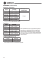
Accuracy (cont’d)
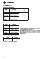
AC Voltage
Range
Accuracy* at
20 Hz to 45 Hz
Accuracy* at
45 Hz to 65 Hz
Accuracy* at
65 Hz to 10 kHz
500.00 mV ± (1.2% + 0.4 mV) ± (0.3% + 0.2 mV) ± (0.4% + 0.25 mV)
5.0000 V ± (1.2% + 0.004 V) ± (0.3% + 0.003 V) ± (0.3% + 0.004 V)
50.000 V ± (1.2% + 0.04 V) ± (0.3% + 0.03 V) ± (0.3% + 0.04 V)
500.00 V Unspecified ± (0.5% + 0.3 V) ± (0.5% + 0.4 V)
1000.0 V Unspecified ± (0.5% + 3 V) ± (0.8% + 4 V) (65 Hz to 1 kHz)
Range
Accuracy* at
10 kHz to 20 kHz
Accuracy* at
20 kHz to 100 kHz
500.00 mV ± (0.5% + 0.3 mV) ± (2.5% + 0.4 mV)**
5.0000 V ± (0.7% + 0.004 V) ± (3.5% + 0.004 V)**
50.000 V ± (0.7% + 0.04 V) ± (3.5% + 0.04 V)**
500.00 V ± (0.7% + 0.4 V) Unspecified
1000.0 V Unspecified Unspecified
*
From 5% to 10% of range: Accuracy percentage of reading + 80 digits.
**
From 5% to 10% of range: Accuracy percentage of reading + 180 digits.
Residual reading less than 50 digits with test leads shorted.
Note: “Digits” refers to the least significant digit (the number in the right-most position).
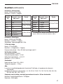
DC Voltage
Range Accuracy Input Impedance
500.00 mV ± (0.02% + 0.02 mV) 10 MΩ, 80 pF nominal
5.0000 V ± (0.02% + 0.0002 V)
10 MΩ, 60 pF nominal
50.000 V ± (0.03% + 0.002 V)
500.00 V ± (0.04% + 0.02 V)
1000.0 V ± (0.15% + 0.2 V)
La page est en cours de chargement...
La page est en cours de chargement...
La page est en cours de chargement...
La page est en cours de chargement...
La page est en cours de chargement...
La page est en cours de chargement...
La page est en cours de chargement...
La page est en cours de chargement...
La page est en cours de chargement...
La page est en cours de chargement...
La page est en cours de chargement...
La page est en cours de chargement...
La page est en cours de chargement...
La page est en cours de chargement...
La page est en cours de chargement...
La page est en cours de chargement...
La page est en cours de chargement...
La page est en cours de chargement...
La page est en cours de chargement...
La page est en cours de chargement...
La page est en cours de chargement...
La page est en cours de chargement...
La page est en cours de chargement...
La page est en cours de chargement...
La page est en cours de chargement...
La page est en cours de chargement...
La page est en cours de chargement...
La page est en cours de chargement...
La page est en cours de chargement...
La page est en cours de chargement...
La page est en cours de chargement...
La page est en cours de chargement...
La page est en cours de chargement...
La page est en cours de chargement...
La page est en cours de chargement...
La page est en cours de chargement...
La page est en cours de chargement...
La page est en cours de chargement...
La page est en cours de chargement...
La page est en cours de chargement...
La page est en cours de chargement...
La page est en cours de chargement...
La page est en cours de chargement...
La page est en cours de chargement...
La page est en cours de chargement...
La page est en cours de chargement...
La page est en cours de chargement...
La page est en cours de chargement...
La page est en cours de chargement...
La page est en cours de chargement...
La page est en cours de chargement...
La page est en cours de chargement...
La page est en cours de chargement...
La page est en cours de chargement...
La page est en cours de chargement...
La page est en cours de chargement...
-
 1
1
-
 2
2
-
 3
3
-
 4
4
-
 5
5
-
 6
6
-
 7
7
-
 8
8
-
 9
9
-
 10
10
-
 11
11
-
 12
12
-
 13
13
-
 14
14
-
 15
15
-
 16
16
-
 17
17
-
 18
18
-
 19
19
-
 20
20
-
 21
21
-
 22
22
-
 23
23
-
 24
24
-
 25
25
-
 26
26
-
 27
27
-
 28
28
-
 29
29
-
 30
30
-
 31
31
-
 32
32
-
 33
33
-
 34
34
-
 35
35
-
 36
36
-
 37
37
-
 38
38
-
 39
39
-
 40
40
-
 41
41
-
 42
42
-
 43
43
-
 44
44
-
 45
45
-
 46
46
-
 47
47
-
 48
48
-
 49
49
-
 50
50
-
 51
51
-
 52
52
-
 53
53
-
 54
54
-
 55
55
-
 56
56
-
 57
57
-
 58
58
-
 59
59
-
 60
60
-
 61
61
-
 62
62
-
 63
63
-
 64
64
-
 65
65
-
 66
66
-
 67
67
-
 68
68
-
 69
69
-
 70
70
-
 71
71
-
 72
72
-
 73
73
-
 74
74
-
 75
75
-
 76
76


Greenlee DM-860A Manuel utilisateur
- Catégorie
- Mesure, test
- Taper
- Manuel utilisateur
- Ce manuel convient également à
dans d''autres langues
- English: Greenlee DM-860A User manual
- español: Greenlee DM-860A Manual de usuario
Documents connexes
-
Greenlee DM-860A Digital Multimeter Manuel utilisateur
-
-
-
-
-
-
-
Greenlee DM-510A Manuel utilisateur
-
-
Autres documents
-
 Valor Fires 820 Manuel utilisateur
-
Metrix MX 200 Le manuel du propriétaire
-
Amprobe AM-52, AM-57 & AM-59 Digital Multimeters Manuel utilisateur
-
Extech Instruments MP530A Manuel utilisateur
-
-
Megger M8035 Manuel utilisateur
-
Chauvin-Arnoux C.A 5003 Manuel utilisateur
-
Promax MZ-805 Manuel utilisateur
