ESAB Powercut-1300/1600 Manuel utilisateur
- Catégorie
- Système de soudage
- Taper
- Manuel utilisateur
Ce manuel convient également à

Powercut-1300/1600
Manual & Mechanized Plasmarc Cutting Package
0558007595 11/2009
This manual provides complete instructions for MANUAL CONSOLES starting with Serial Number PxxJ824xxx, June 2008
This manual provides complete instructions for MECHANIZED CONSOLES starting with Serial Number PxxJ824xxx, June 2008
Instruction Manual (EN)
Manuel d’instructions (FR)

2
This equipment will perform in conformity with the description thereof contained in this manual and accompa-
nying labels and/or inserts when installed, operated, maintained and repaired in accordance with the instruc-
tions provided. This equipment must be checked periodically. Malfunctioning or poorly maintained equipment
should not be used. Parts that are broken, missing, worn, distorted or contaminated should be replaced imme-
diately. Should such repair or replacement become necessary, the manufacturer recommends that a telephone
or written request for service advice be made to the Authorized Distributor from whom it was purchased.
This equipment or any of its parts should not be altered without the prior written approval of the manufacturer.
The user of this equipment shall have the sole responsibility for any malfunction which results from improper
use, faulty maintenance, damage, improper repair or alteration by anyone other than the manufacturer or a ser-
vice facility designated by the manufacturer.
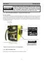
BE SURE THIS INFORMATION REACHES THE OPERATOR.
YOU CAN GET EXTRA COPIES THROUGH YOUR SUPPLIER.
These INSTRUCTIONS are for experienced operators. If you are not fully familiar with the
principles of operation and safe practices for arc welding and cutting equipment, we urge
you to read our booklet, “Precautions and Safe Practices for Arc Welding, Cutting, and
Gouging,” Form 52-529. Do NOT permit untrained persons to install, operate, or maintain
this equipment. Do NOT attempt to install or operate this equipment until you have read
and fully understand these instructions. If you do not fully understand these instructions,
contact your supplier for further information. Be sure to read the Safety Precautions be-
fore installing or operating this equipment.
CAUTION
USER RESPONSIBILITY
READ AND UNDERSTAND THE INSTRUCTION MANUAL BEFORE INSTALLING OR OPERATING.
PROTECT YOURSELF AND OTHERS!

3
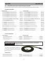
TABLE OF CONTENTS
SECTION PAGE
English ................................................................................................................................................................................5
French ..............................................................................................................................................................................51

4

5
Powercut-1300/1600
Manual & Mechanized Plasmarc Cutting Package
0558007595
Instruction Manual (EN)
This manual provides complete instructions for MANUAL CONSOLES starting with Serial Number PxxJ824xxx, June 2008
This manual provides complete instructions for MECHANIZED CONSOLES starting with Serial Number PxxJ824xxx, June 2008

6
This equipment will perform in conformity with the description thereof contained in this manual and accompa-
nying labels and/or inserts when installed, operated, maintained and repaired in accordance with the instruc-
tions provided. This equipment must be checked periodically. Malfunctioning or poorly maintained equipment
should not be used. Parts that are broken, missing, worn, distorted or contaminated should be replaced imme-
diately. Should such repair or replacement become necessary, the manufacturer recommends that a telephone
or written request for service advice be made to the Authorized Distributor from whom it was purchased.
This equipment or any of its parts should not be altered without the prior written approval of the manufacturer.
The user of this equipment shall have the sole responsibility for any malfunction which results from improper
use, faulty maintenance, damage, improper repair or alteration by anyone other than the manufacturer or a ser-
vice facility designated by the manufacturer.
BE SURE THIS INFORMATION REACHES THE OPERATOR.
YOU CAN GET EXTRA COPIES THROUGH YOUR SUPPLIER.
These INSTRUCTIONS are for experienced operators. If you are not fully familiar with the
principles of operation and safe practices for arc welding and cutting equipment, we urge
you to read our booklet, “Precautions and Safe Practices for Arc Welding, Cutting, and
Gouging,” Form 52-529. Do NOT permit untrained persons to install, operate, or maintain
this equipment. Do NOT attempt to install or operate this equipment until you have read
and fully understand these instructions. If you do not fully understand these instructions,
contact your supplier for further information. Be sure to read the Safety Precautions be-
fore installing or operating this equipment.
CAUTION
USER RESPONSIBILITY
READ AND UNDERSTAND THE INSTRUCTION MANUAL BEFORE INSTALLING OR OPERATING.
PROTECT YOURSELF AND OTHERS!

7
TABLE OF CONTENTS
SECTION TITLE .........................................................................................................................................PAGE
SECTION 1 Safety Precautions ............................................................................................................................................................ 9
Powercut-1300/1600 MANUAL PLASMARC CUTTING PACKAGE ................................... 11
SECTION 2 DESCRIPTION .................................................................................................................................................................... 13
2.0 General ............................................................................................................................................................................. 13
2.1 Scope................................................................................................................................................................................... 13
2.2 Powercut-1300/1600 Manual Plasma ....................................................................................................................... 14
2.3 Manual Package Ordering Information ..................................................................................................................15
2.4 PT-38 Torch Data ............................................................................................................................................................. 15
2.5 Optional Accessories .....................................................................................................................................................16
SECTION 3 INSTALLATION .................................................................................................................................................................. 17
3.0 Installation ......................................................................................................................................................................... 17
3.1 General ............................................................................................................................................................................. 17
3.2 Equipment Required ..................................................................................................................................................... 17
3.3 Location ............................................................................................................................................................................. 17
3.4 Inspection .......................................................................................................................................................................... 17
3.5 Primary Input Connections .........................................................................................................................................18
3.5.1 Input Voltage Changeover - 230/460 Voltage Units ONLY ..............................................................................20
3.5.2 Input Air Connection / Fuse Replacement ............................................................................................................20
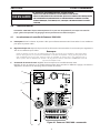
3.6 Provisions for Automation ........................................................................................................................................... 21
3.7 Secondary Output Connections for Manual Cutting.........................................................................................22
3.8 PT-38 Torch Installation ................................................................................................................................................22
SECTION 4 OPERATION .......................................................................................................................................................................25
4.0 Operation ..........................................................................................................................................................................25
4.1 Powercut-1300/1600 Controls .................................................................................................................................25
4.2 Cutting with the Powercut-1300/1600 using the PT-38 torch ........................................................................28
4.3 Stand-o Guide ...............................................................................................................................................................30
4.4 Drag Cutting 40 Amp ....................................................................................................................................................30
4.5 Gouging with the Powercut-1300/1600 using the PT-38 torch ......................................................................30
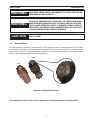
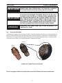
4.6 Electrode Wear ................................................................................................................................................................31

8
TABLE OF CONTENTS
SECTION 5 MAINTENANCE ................................................................................................................................................................97
5.0 General ...............................................................................................................................................................................99
5.1 Inspection and Cleaning ..............................................................................................................................................99
5.2 Common Cutting Problems ......................................................................................................................................100
5.3 IGBT Handling ................................................................................................................................................................101
5.4 Module Replacement ..................................................................................................................................................101
SECTION 6 TROUBLESHOOTING ....................................................................................................................................................103
6.0 Troubleshooting ............................................................................................................................................................103
6.1 List of Help Codes .........................................................................................................................................................104
SECTION 7 REPLACEMENT PARTS..................................................................................................................................................105
7.0 Replacement Parts .......................................................................................................................................................105
7.1 General .............................................................................................................................................................................105
7.2 Ordering ...........................................................................................................................................................................105
7.3 Torque Recommendations ........................................................................................................................................106
7.4 Selecting Air Pressure Units of Measure ...............................................................................................................107
7.5 Control/Display Board Assembly ........................................................................................................................... 107
7.6 Power Board Assembly ...............................................................................................................................................108
Diagrams and Parts List .................................................................................................................... attached packet
SECTION 2 DESCRIPTION ....................................................................................................................................................................35
2.0 General .............................................................................................................................................................................35
2.1 Scope...................................................................................................................................................................................35
2.2 Powercut-1300/1600 Mechanized Plasma .............................................................................................................36
2.3 Mechanized Package Ordering Information ........................................................................................................36
2.4 PT-37 Torch Data .............................................................................................................................................................37
2.5 Optional Accessories .....................................................................................................................................................38
SECTION 3 INSTALLATION ..................................................................................................................................................................39
3.0 Installation .........................................................................................................................................................................39
3.1 General .............................................................................................................................................................................39
3.2 Equipment Required .....................................................................................................................................................39
3.3 Location .............................................................................................................................................................................39
3.4 Inspection ..........................................................................................................................................................................35
3.5 Primary Input Connections .........................................................................................................................................40
3.5.1 Input Voltage Changeover - 230/460 Voltage Units ONLY ..............................................................................42
3.5.2 Input Air Connection / Fuse Replacement ............................................................................................................42
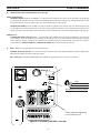
3.6 CNC Interface Connection ...........................................................................................................................................43
3.7 Voltage Divider Adjustment .......................................................................................................................................44
3.7.1 Output Voltage Sample ................................................................................................................................................44
3.8 Secondary Output Connections for Mechanized Cutting ...............................................................................45
3.9 PT-37 Torch Installation ................................................................................................................................................45
SECTION 4 OPERATION .......................................................................................................................................................................47
4.0 Operation ..........................................................................................................................................................................47
4.1 Powercut-1300/1600 Controls .................................................................................................................................47
4.2 Cutting with the Powercut-1300/1600 using the PT-37 torch .........................................................................50
4.3 Electrode Wear ................................................................................................................................................................50
Powercut-1300/1600 MECHANIZED PLASMARC CUTTING PACKAGE .......................33
MAINTENANCE, TROUBLESHOOTING, SCHEMATIC DIAGRAMS, REPLACEMENT PARTS ......... 97

9
SECTION 1 SAFETY PRECAUTIONS
1.0 Safety Precautions
Users of ESAB welding and plasma cutting equipment have the ultimate responsibility for ensuring that
anyone who works on or near the equipment observes all the relevant safety precautions. Safety precautions
must meet the requirements that apply to this type of welding or plasma cutting equipment. The following
recommendations should be observed in addition to the standard regulations that apply to the workplace.
All work must be carried out by trained personnel well acquainted with the operation of the welding or plasma
cutting equipment. Incorrect operation of the equipment may lead to hazardous situations which can result in
injury to the operator and damage to the equipment.
1. Anyone who uses welding or plasma cutting equipment must be familiar with:
- its operation
- location of emergency stops
- its function
- relevant safety precautions
- welding and / or plasma cutting
2. The operator must ensure that:
- no unauthorized person stationed within the working area of the equipment when it is started up.
- no one is unprotected when the arc is struck.
3. The workplace must:
- be suitable for the purpose
- be free from drafts
4. Personal safety equipment:
- Always wear recommended personal safety equipment, such as safety glasses, ame proof
clothing, safety gloves.
- Do not wear loose tting items, such as scarves, bracelets, rings, etc., which could become
trapped or cause burns.
5. General precautions:
- Make sure the return cable is connected securely.
- Work on high voltage equipment may only be carried out by a qualied electrician.
- Appropriate re extinquishing equipment must be clearly marked and close at hand.
- Lubrication and maintenance must not be carried out on the equipment during operation.
The following publication, which is available from the Canadian Standards Association, is recommended to you:
CSA - W117.2 - "Code for Safety in Welding and Cutting".

10
SECTION 1 SAFETY PRECAUTIONS
WELDING AND PLASMA CUTTING CAN BE INJURIOUS TO YOURSELF AND
OTHERS. TAKE PRECAUTIONS WHEN WELDING OR CUTTING. ASK FOR
YOUR EMPLOYER’S SAFETY PRACTICES WHICH SHOULD BE BASED ON
MANUFACTURERS’ HAZARD DATA.
ELECTRIC SHOCK - Can kill.
- Install and earth (ground) the welding or plasma cutting unit in accordance with applicable standards.
- Do not touch live electrical parts or electrodes with bare skin, wet gloves or wet clothing.
- Insulate yourself from earth and the workpiece.
- Ensure your working stance is safe.
FUMES AND GASES - Can be dangerous to health.
- Keep your head out of the fumes.
- Use ventilation, extraction at the arc, or both, to take fumes and gases away from your breathing zone
and the general area.
ARC RAYS - Can injure eyes and burn skin.
- Protect your eyes and body. Use the correct welding / plasma cutting screen and lter lens and wear
protective clothing.
- Protect bystanders with suitable screens or curtains.
FIRE HAZARD
- Sparks (spatter) can cause re. Make sure therefore that there are no inammable materials nearby.
NOISE - Excessive noise can damage hearing.
- Protect your ears. Use earmus or other hearing protection.
- Warn bystanders of the risk.
MALFUNCTION - Call for expert assistance in the event of malfunction.
READ AND UNDERSTAND THE INSTRUCTION MANUAL BEFORE INSTALLING OR OPERATING.
PROTECT YOURSELF AND OTHERS!
WARNING

11
MANUAL PLASMARC CUTTING PACKAGE
Powercut-1300/1600

12

13
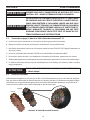
USE THE ESAB PT38 PLASMARC TORCH WITH MANUAL CONSOLES.
USE OF TORCHES NOT DESIGNED FOR USE WITH THIS CONSOLE COULD
CREATE AN ELECTRIC SHOCK HAZARD.
SECTION 2 DESCRIPTION
WARNING
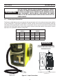
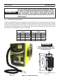
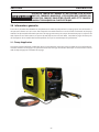
2.0 General
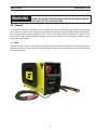
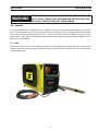
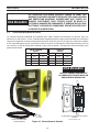
As shipped, the PowerCut 1300/1600 is fully assembled and ready to cut after being connected to input power
and a source of compressed air. The Powercut package uses the heavy-duty PT-38 (Manual Plasma) torch to de-
liver cutting power for severing materials up to 1-1/2 inch (38 mm) thick on the PC-1300 and 1-3/4 inch (45 mm)
thick on the PC-1600. Refer to the following pages for descriptions of the Powercut packages available as well as
performance specications.
2.1 Scope
The purpose of this manual is to provide the operator with all the information required to install and operate the
Powercut plasma arc cutting package. Technical reference material is also provided to assist in troubleshooting
the cutting package.

14
SECTION 2 DESCRIPTION
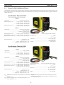
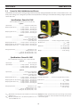
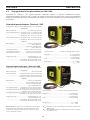
Specications: PowerCut 1300
Cuts 1-1/4 in. (32 mm); severs 1-1/2 in. (38 mm)
The PowerCut 1300/1600 plasma cutting package combines the newly redesigned PowerCut 1300/1600 console and PT-38 torch. The
PT-38 plasma cutting torch is designed to provide increased performance and longer consumable life resulting in higher production
rates at lower costs.
2.2 PowerCut 1300/1600 Manual Plasma
*S
sc min
: Minimum short circuit power on the network in accordance with
IEC61000-3-12.
*Z
max
: Maximum permissible line on the network impedance in accor-
dance with IEC61000-3-11.
Specications: PowerCut 1600
Cuts 1-1/2 in. (38 mm); severs 1-3/4 in. (45 mm)
Duty Cycle: The duty cycle refers to the time as a percentage of a ten-min-
ute period that you can cut at a certain load without overheating. The duty
cycle is valid for 40 degrees C.
1 phase
1 phase Input ............................................................................. 230 vac, 60 Hz, 79A
1 phase Output ...................................... 90 amps @ 125vdc - 40% duty cycle
....................................... 70 amps @ 125vdc - 60% duty cycle
.......................................60 amps @ 125vdc - 100% duty cycle
3 phase
3 phase Input ............................................................ 208/230 vac, 60 Hz, 44/47 A
............................................................................460 vac, 60 Hz, 23 A
......................................................380/400 vac, 50/60 Hz, 21/20 A
............................................................................575 vac, 60 Hz, 20 A
Output (3 phase 208 vac) ................... 90 amps @ 125vdc - 60% duty cycle
...................70 amps @ 125vdc - 100% duty cycle
Output (3 phase 230, 460, 575 vac) 90 amps @ 150vdc - 60% duty cycle
70 amps @ 150vdc - 100% duty cycle
Output (3 phase 380-400 vac) .......... 90 amps @ 115vdc - 60% duty cycle
..........70 amps @ 115vdc - 100% duty cycle
Voltage requirements ..........................................................Idle 208V, -2%, +10%
.................................................. Cutting 208V, -4%, +15%
..........................Idle 230, 380, 400, 460, 575V, +/- 10%
..................Cutting 230, 380, 400, 460, 575V, +/- 15%
1 phase
1 phase Input ............................................................ 208/230 vac, 60 Hz, 57/50 A
Output (1 phase 208 vac) .................. 70 amps @ 125vdc - 40% duty cycle
.................. 60 amps @ 125vdc - 60% duty cycle
..................50 amps @ 125vdc - 100% duty cycle
Output (1 phase 230 vac) .................. 70 amps @ 125vdc - 60% duty cycle
...................60 amps @ 125vdc - 100% duty cycle
3 phase
3 phase Input ........................................................... 208/230 vac, 60 Hz, 34/36 A
........................................................................... 460 vac, 60 Hz, 18 A
.....................................................380/400 vac, 50/60 Hz, 19/18 A
........................................................................... 575 vac, 60 Hz, 15 A
Output (3 phase 208 vac) ...................70 amps @ 125vdc - 100% duty cycle
Output (3 phase 230, 460, 575 vac) 70 amps @ 150vdc - 100% duty cycle
Output (3 phase 380-400 vac) ..........70 amps @ 115vdc - 100% duty cycle
Voltage requirements ..........................................................Idle 208V, -2%, +10%
...................................................Cutting 208V, -4%, +15%
...........................Idle 230, 380, 400, 460, 575V, +/- 10%
...................Cutting 230, 380, 400, 460, 575V, +/- 15%
Air Supply Requirements ..............500 cfh @ 90 psig (236 l/min @ 6.2 bars)
CE 380-400 vac .....................................................................................*S
sc min
4 MVA
.................................................................................... *Z
max
0.04
Dimensions ................................................................................W = 12.7” (322 mm)
................................................................................ H = 14.9” (379 mm)
................................................................................ D = 27.8” (706 mm)
Weight .................................................................................................90 lbs. (40.8 kg)
Air Supply Requirements ..............500 cfh @ 90 psig (236 l/min @ 6.2 bars)
CE 380-400 vac ....................................................................................*S
sc min
4 MVA
................................................................................... *Z
max
0.04
Dimensions ................................................................................W = 12.7” (322 mm)
................................................................................ H = 14.9” (379 mm)
................................................................................ D = 27.8” (706 mm)
Weight .................................................................................................90 lbs. (40.8 kg)

15
SECTION 2 DESCRIPTION
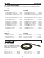
2.4 PT-38 Torch Data
Powercut-1300/1600 manual plasma cutting pack-
ages use the PT-38 torch. For dimensions and break-
down of parts, refer to torch manual.
2.3 Package Ordering Information
Powercut-1300:
208-230/460 V PT-38 25 ft (7.6 m) ...................................................................................................................................................... 0558007221
208-230/460 V PT-38 50 ft (15.2 m) .................................................................................................................................................... 0558007222
208-230/460 V PT-38 25 ft (7.6 m) BL .............................................................................................................................................. 0558007221F
380-400 V CE PT-38 25 ft (7.6 m) ........................................................................................................................................................ 0558007225
380-400 V CE PT-38 50 ft (15.2 m) ...................................................................................................................................................... 0558007226
400 V PT-38 25 ft (7.6 m) .........................................................................................................................................................................0558007635
460 V PT-38 25 ft (7.6 m) ........................................................................................................................................................................ 0558008321
460 V PT-38 50 ft (15.2 m) ..................................................................................................................................................................... 0558008322
575 V PT-38 25 ft (7.6 m) BL .................................................................................................................................................................. 0558007228
575 V PT-38 50 ft (15.2 m) BL ................................................................................................................................................................ 0558007229
Powercut-1600:
208-230/460 V PT-38 25 ft (7.6 m) .......................................................................................................................................................0558007231
208-230/460 V PT-38 50 ft (15.2 m) .................................................................................................................................................... 0558007232
208-230/460 V PT-38 25 ft (7.6 m) BL .............................................................................................................................................. 0558007231F
380-400 V CE PT-38 25 ft (7.6 m) ........................................................................................................................................................ 0558007235
380-400 V CE PT-38 50 ft (15.2 m) ...................................................................................................................................................... 0558007236
400 V PT-38 25 ft (7.6 m) .........................................................................................................................................................................0558007637
460 V PT-38 25 ft (7.6 m) BL .................................................................................................................................................................. 0558008324
460 V PT-38 50 ft (15.2 m) BL ............................................................................................................................................................... 0558008325
575 V PT-38 25 ft (7.6 m) BL .................................................................................................................................................................. 0558007238
575 V PT-38 50 ft (15.2 m) BL ................................................................................................................................................................ 0558007239
The components that are included in the Powercut-1300/1600 manual packages may be purchased separately by using the
appropriate P/N when placing orders. Individual part numbers are listed below:
Consoles:
Powercut-1300:
208-230/460 V Console..........................................................................................................................................................................0558007220
208-230/460 V Console BL ..................................................................................................................................................................0558007220F
380-400 V CE Console ............................................................................................................................................................................0558007224
400 V Console............................................................................................................................................................................................0558007634
460 V Console............................................................................................................................................................................................0558008320
575 V Console BL ...................................................................................................................................................................................... 0558007227
Powercut-1600:
208-230/460 V Console..........................................................................................................................................................................0558007230
208-230/460 V Console BL ..................................................................................................................................................................0558007230F
380-400 V CE Console ............................................................................................................................................................................0558007234
400 V Console............................................................................................................................................................................................0558007636
460 V Console............................................................................................................................................................................................0558008323
575 V Console BL ...................................................................................................................................................................................... 0558007237
PT-38 Torches:
PT-38 Torch, 25' (7.6 m) .......................................................................................................................................................................... 0558006786
PT-38 Torch, 50' (15.2 m) ....................................................................................................................................................................... 0558006787

16
SECTION 2 DESCRIPTION
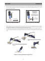
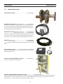
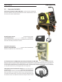
Powercut-1300/1600 Mechanized Conversion kit .....................................p/n 0558007885
Adds automated mechanized capability to an existing manual machine. Refer to mechanized section of this manual for
CNC Interface connection. Requires software version 1.04 or higher (displayed during power-up). Refer to Section 4,
Subsection 4.1.E1. Contact factory for any required software updates.
Gas Flow Measuring Kit .............p/n 19765 ("CE" units - 0558000739)
Valuable troubleshooting tool allows measurement of the actual air
ow through the torch.
Remote Hand Switch with 25 ft. (7.6m) lead ............... p/n 0558008349
Enables non-automated mechanized cutting using the PT-37 torch.
Can be used on machines equipped with or without CNC interface
connection pigtail. Connects to the torch cable receptacle through
the front panel access door strain relief.
2.5 Optional Accessories:
Powercut-900/1300/1600 Cart ....................................................p/n 0558007898
Enables operator to easily transport the power source , work cable and power
cord.
Powercut-900/1300/1600 Water Separator ...........p/n 0558007897
Improves air quality by removing water.

17
3.1 General
Proper installation is important for satisfactory and trouble-free operation of the Powercut cutting package. It is
suggested that each step in this section be studied carefully and followed closely.
3.2 Equipment Required
A source of clean, dry air that supplies 500 cfh (236 l/m) at 90 psig (6.2 bar) is required for the cutting operation.
The air supply should not exceed 150 psig (10.3 bar) (the maximum inlet pressure rating of the air lter-regulator
supplied with the package).
3.3 Location
Adequate ventilation is necessary to provide proper cooling of the Powercut. The amount of dirt, dust, and
excessive heat to which the equipment is exposed, should be minimized. There should be at least one foot of
clearance between the Powercut power source and wall or any other obstruction to allow freedom of air move-
ment through the power source.
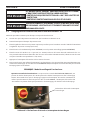
3.4 Inspection
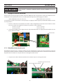
A. Remove the shipping container and all packing material and inspect for evidence of concealed damage
which may not have been apparent upon receipt of the Powercut. Notify the carrier of any defects or dam-
age at once.
B. Check container for any loose parts prior to disposing of shipping materials.
C. Check air louvers and any other openings to ensure that any obstruction is removed.
INSTALLING OR PLACING ANY TYPE OF FILTERING DEVICE WILL RE
STRICT THE VOLUME OF INTAKE AIR, THEREBY SUBJECTING THE
POWER SOURCE INTERNAL COMPONENTS TO OVERHEATING. THE
WARRANTY IS VOID IF ANY TYPE OF FILTER DEVICE IS USED.
3.0 Installation
SECTION 3 INSTALLATION
WARNING

18
ELECTRIC SHOCK CAN KILL! PRECAUTIONARY MEASURES SHOULD
BE TAKEN TO PROVIDE MAXIMUM PROTECTION AGAINST ELECTRI
CAL SHOCK. BE SURE THAT ALL POWER IS OFF BY OPENING THE LINE
WALL DISCONNECT SWITCH AND BY UNPLUGGING THE POWER
CORD TO THE UNIT WHEN CONNECTIONS ARE MADE INSIDE OF THE
POWER SOURCE.
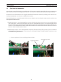
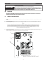
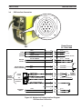
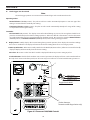
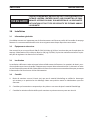
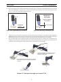
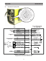
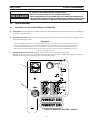
3.5 Primary Input Connections
The Powercut-1300/1600 consoles are equipped with approximately 10 ft. of 4-conductor input power cable for
3 phase connection. If single-phase connection is desired, cap the unused wire on the input power cable per
chart below. When operating this machine from a single-phase source, it must be connected to a dedicated 100
amp feed. Due to the higher input current requirements, the duty cycle of the machine is lower than in 3 phase
operation. See specication section or rating plate.
CUSTOMER FUSED LINE DISCONNECT SWITCH
(See Table 3-1)
PRIMARY INPUT
POWER CABLE
Figure 3-1. Input Connections
SECTION 3 INSTALLATION
WARNING
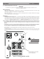
STANDARD UNITS
(NON-CE)
CE UNITS
(EUROPE)
PHASE 3 1 PHASE 3 1
L1 Black Black L1 Brown Brown
L2 Red - L2 Black -
L3 White White L3 Gray Gray
GND Green Green GND Green/Yel Green/Yel
INSULATE UNUSED POWER CORD
CONDUCTOR WHEN CONNECTING
FOR SINGLE PHASE.
WARNING

19
Before connecting to input power, make sure there is a line (wall) disconnect switch with fuses or circuit breakers
at the main power panel. You may either use the factory-installed input power cable (4/c, type SO (90 °C), 10 ft
(3.1 m) length) or provide your own input power leads. If you choose to provide your own, make sure they are
insulated copper conductors. You must have two (single-phase) or three (3 phase) power leads and one ground
wire. The wires may be heavy rubber covered cable or may be run in a solid or exible conduit. Refer to Table 3-1
for recommended input conductors and line fuse sizes.
BEFORE MAKING ANY CONNECTIONS TO THE POWER SOURCE OUT
PUT TERMINALS, MAKE SURE THAT ALL PRIMARY INPUT POWER TO
THE POWER SOURCE IS DEENERGIZED OFF AT THE MAIN DISCON
NECT SWITCH AND THAT THE INPUT POWER CABLE IS UNPLUGGED.
THE CHASSIS MUST BE CONNECTED TO AN APPROVED ELECTRICAL
GROUND. FAILURE TO DO SO MAY RESULT IN ELECTRICAL SHOCK, SE
VERE BURNS OR DEATH.
SECTION 3 INSTALLATION
WARNING
WARNING
WARNING
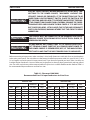
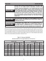
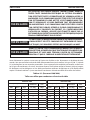
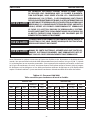
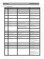
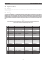
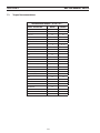
Table 3-1. (Powercut-1300/1600)
Recommended Sizes For Input Conductors and Line Fuses
ELECTRIC SHOCK CAN KILL! BEFORE MAKING ELECTRICAL INPUT CON
NECTIONS TO THE POWER SOURCE, "MACHINERY LOCKOUT PRO
CEDURES" SHOULD BE EMPLOYED. IF THE CONNECTIONS ARE TO BE
MADE FROM A LINE DISCONNECT SWITCH, PLACE THE SWITCH IN THE
OFF POSITION AND PADLOCK IT TO PREVENT INADVERTENT TRIPPING.
IF THE CONNECTION IS MADE FROM A FUSEBOX, REMOVE THE CORRE
SPONDING FUSES AND PADLOCK THE BOX COVER. IF IT IS NOT POSSI
BLE TO USE PADLOCKS, ATTACH A RED TAG TO THE LINE DISCONNECT
SWITCH OR FUSE BOX WARNING OTHERS THAT THE CIRCUIT IS BEING
WORKED ON.
PowerCut 1300
Input Requirements Input & Gnd
Conductors
Line
Fuse
Volts Phase Amps Cu / Awg Amps
208 1 57 6 75
208 3 34 6 45
230 1 50 6 70
230 3 36 6 50
400 3 18 10 25
380(CE) 3 19 6 mm
2
25
400(CE) 3 18 6 mm
2
25
460 3 18 10 25
575 3 15 10 20
PowerCut 1600
Input Requirements Input & Gnd
Conductors
Line
Fuse
Volts Phase Amps Cu / Awg Amps
208 3 44 6 60
230 1 79 6 100
230 3 47 6 60
400 3 20 10 30
380(CE) 3 21 6 mm
2
30
400(CE) 3 20 6 mm
2
30
460 3 23 10 30
575 3 20 10 30

20
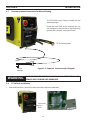
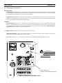
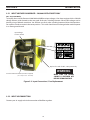
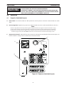
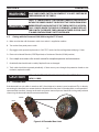
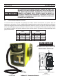
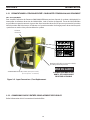
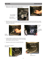
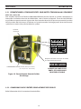
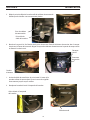
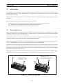
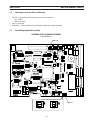
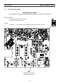
3.5.1 INPUT VOLTAGE CHANGEOVER - 230/460 VOLTAGE UNITS ONLY
208 - 230 or 460 Mode
To simplify the use of the Powercut-1300/1600 with dierent input voltages, it has been equipped with a 230/460
voltage selector switch located on the rear panel of the unit. Switching between 230 and 460 voltages can be
done by using a athead screwdriver. You will hear two clicks when switching between 230 and 460 positions.
Do not allow switch to remain in the center position. This switch should never be changed when machine power
is on. Damage could result.
Input Voltage
Selector Switch
SECTION 3 INSTALLATION
Figure 3-2. Input Connections / Fuse Replacement
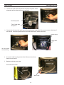
Connect your air supply to the inlet connection of the lter-regulator.
3.5.2 INPUT AIR CONNECTION
Replace fuse with Slo-Blo, 2 Amp, 600 V only
MAKE SURE THE POWER
SOURCE IS SWITCHED OFF
BEFORE REMOVING FUSE.
WARNING
Pre-ltered DRY AIR SUPPLY (Customer Supplied)
(90 - 150 psi / 6.2 - 10.3 bars)
ELECTRIC SHOCK CAN KILL! PRECAUTIONARY MEASURES SHOULD
BE TAKEN TO PROVIDE MAXIMUM PROTECTION AGAINST ELECTRI
CAL SHOCK. BE SURE THAT ALL POWER IS OFF BY OPENING THE LINE
WALL DISCONNECT SWITCH AND BY UNPLUGGING THE POWER
CORD TO THE UNIT WHEN RECONNECTING FOR 208 VAC INPUT.
WARNING
La page est en cours de chargement...
La page est en cours de chargement...
La page est en cours de chargement...
La page est en cours de chargement...
La page est en cours de chargement...
La page est en cours de chargement...
La page est en cours de chargement...
La page est en cours de chargement...
La page est en cours de chargement...
La page est en cours de chargement...
La page est en cours de chargement...
La page est en cours de chargement...
La page est en cours de chargement...
La page est en cours de chargement...
La page est en cours de chargement...
La page est en cours de chargement...
La page est en cours de chargement...
La page est en cours de chargement...
La page est en cours de chargement...
La page est en cours de chargement...
La page est en cours de chargement...
La page est en cours de chargement...
La page est en cours de chargement...
La page est en cours de chargement...
La page est en cours de chargement...
La page est en cours de chargement...
La page est en cours de chargement...
La page est en cours de chargement...
La page est en cours de chargement...
La page est en cours de chargement...
La page est en cours de chargement...
La page est en cours de chargement...
La page est en cours de chargement...
La page est en cours de chargement...
La page est en cours de chargement...
La page est en cours de chargement...
La page est en cours de chargement...
La page est en cours de chargement...
La page est en cours de chargement...
La page est en cours de chargement...
La page est en cours de chargement...
La page est en cours de chargement...
La page est en cours de chargement...
La page est en cours de chargement...
La page est en cours de chargement...
La page est en cours de chargement...
La page est en cours de chargement...
La page est en cours de chargement...
La page est en cours de chargement...
La page est en cours de chargement...
La page est en cours de chargement...
La page est en cours de chargement...
La page est en cours de chargement...
La page est en cours de chargement...
La page est en cours de chargement...
La page est en cours de chargement...
La page est en cours de chargement...
La page est en cours de chargement...
La page est en cours de chargement...
La page est en cours de chargement...
La page est en cours de chargement...
La page est en cours de chargement...
La page est en cours de chargement...
La page est en cours de chargement...
La page est en cours de chargement...
La page est en cours de chargement...
La page est en cours de chargement...
La page est en cours de chargement...
La page est en cours de chargement...
La page est en cours de chargement...
La page est en cours de chargement...
La page est en cours de chargement...
La page est en cours de chargement...
La page est en cours de chargement...
La page est en cours de chargement...
La page est en cours de chargement...
La page est en cours de chargement...
La page est en cours de chargement...
La page est en cours de chargement...
La page est en cours de chargement...
La page est en cours de chargement...
La page est en cours de chargement...
La page est en cours de chargement...
La page est en cours de chargement...
La page est en cours de chargement...
La page est en cours de chargement...
La page est en cours de chargement...
La page est en cours de chargement...
La page est en cours de chargement...
La page est en cours de chargement...
-
 1
1
-
 2
2
-
 3
3
-
 4
4
-
 5
5
-
 6
6
-
 7
7
-
 8
8
-
 9
9
-
 10
10
-
 11
11
-
 12
12
-
 13
13
-
 14
14
-
 15
15
-
 16
16
-
 17
17
-
 18
18
-
 19
19
-
 20
20
-
 21
21
-
 22
22
-
 23
23
-
 24
24
-
 25
25
-
 26
26
-
 27
27
-
 28
28
-
 29
29
-
 30
30
-
 31
31
-
 32
32
-
 33
33
-
 34
34
-
 35
35
-
 36
36
-
 37
37
-
 38
38
-
 39
39
-
 40
40
-
 41
41
-
 42
42
-
 43
43
-
 44
44
-
 45
45
-
 46
46
-
 47
47
-
 48
48
-
 49
49
-
 50
50
-
 51
51
-
 52
52
-
 53
53
-
 54
54
-
 55
55
-
 56
56
-
 57
57
-
 58
58
-
 59
59
-
 60
60
-
 61
61
-
 62
62
-
 63
63
-
 64
64
-
 65
65
-
 66
66
-
 67
67
-
 68
68
-
 69
69
-
 70
70
-
 71
71
-
 72
72
-
 73
73
-
 74
74
-
 75
75
-
 76
76
-
 77
77
-
 78
78
-
 79
79
-
 80
80
-
 81
81
-
 82
82
-
 83
83
-
 84
84
-
 85
85
-
 86
86
-
 87
87
-
 88
88
-
 89
89
-
 90
90
-
 91
91
-
 92
92
-
 93
93
-
 94
94
-
 95
95
-
 96
96
-
 97
97
-
 98
98
-
 99
99
-
 100
100
-
 101
101
-
 102
102
-
 103
103
-
 104
104
-
 105
105
-
 106
106
-
 107
107
-
 108
108
-
 109
109
-
 110
110


ESAB Powercut-1300/1600 Manuel utilisateur
- Catégorie
- Système de soudage
- Taper
- Manuel utilisateur
- Ce manuel convient également à
dans d''autres langues
- English: ESAB Powercut-1300/1600 User manual
Documents connexes
-
ESAB ESP-101 Manuel utilisateur
-
ESAB Precisionmaster Gas Saver "Accumulator" Manuel utilisateur
-
ESAB PT-38 Plasmarc Cutting Torches Manuel utilisateur
-
-
-
-
-
-
-