Fire Magic Aurora Built-In Grill Manuel utilisateur
- Catégorie
- Barbecues
- Taper
- Manuel utilisateur

1
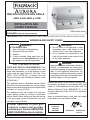
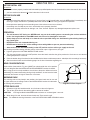
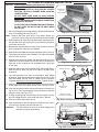
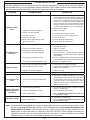
IMPORTANT: READ THESE INSTRUCTIONS CAREFULLY BEFORE STARTING INSTALLATION OR USE.
BUILT-IN OUTDOOR GAS GRILLS
DANGER:
IF YOU SMELL GAS:
1. Shut off the gas to the appliance.
2. Extinguish any open flame.
3. Open lid.
4. If odor continues, keep away from the
appliance and immediately call your
gas supplier or the fire department.
WARNING:
1. Do not store or use gasoline or other
flammable vapors and liquids in the
vicinity of this or any other appliance.
2. An LP cylinder not connected for use
shall not be stored in the vicinity of this
or any other appliance.
CODE AND SUPPLY REQUIREMENTS: This
grill must be installed in accordance with local
codes and ordinances, or, in the absence of local
codes, with the latest National Fuel Gas Code
(ANSI Z223.1/NFPA 54), or Natural Gas and
Propane Storage and Handling Installation Code
(CSA-B149.1).
This appliance and its dedicated manual shutoff
valve must be disconnected from the gas-supply
piping system when testing the system at pressures
in excess of ½ psig (3.5 kPa).
This appliance must be isolated from the gas-
supply piping system by closing its dedicated
manual shutoff valve during any pressure testing
of the gas-supply system at pressures up to and
including ½ psig (3.5 kPa).
All electrical outlets in the vicinity of the grill must
be properly grounded in accordance with local
codes, or, in the absence of local codes, with the
National Electrical Code, ANSI/NFPA 70, or the
Canadian Electrical Code, CSA C22.1, whichever
is applicable.
Keep all electrical-supply cords and fuel-supply
hoses away from any heated surface.
Robert H. Peterson Co. • 14724 East Proctor Avenue • City of Industry, CA 91746
INSTALLATION AND
OWNER’S MANUAL
INSTALLER: Leave these instructions with consumer.
CONSUMER: Retain for future reference.
WARNING:
Improper installation, adjustment, alteration,
service, or maintenance can cause injury
or property damage. For proper installation,
refer to the installation instructions. For
assistance or additional information, consult
a qualified professional service technician,
service agency, or the gas supplier.
WARNINGS AND SAFETY CODES
Proper operation of your grill
requires prompt and periodic
maintenance. See the SERVICING
AND CLEANING section for details.
Certified to: ANSI Z21.58
CSA 1.6
US
®
C
GETTING STARTED
ONLY TO BE USED OUTDOORS
Cooking Grid U.S.
Patent Nos.
D857,453
D862,984
REV 0 - B - 2006190710
L-C2-607
A790i model shown
A430i, A540i, A660i, & A790i

2
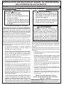
IMPORTANT: LISEZ CES INSTRUCTIONS SOIGNEUSEMENT AVANT DE COMMENCER L’INSTALLATION OU L’UTILISATION
GRIL EXTÉRIEUR DE GAZ DU BUILT-IN
DANGER:
SI VOUS SENTEZ LE GAZ :
1. Coupez le gaz à l’appareil.
2. Éteignez-vous n’importe quelle flamme nue.
3. Ouvrez le couvercle.
4. Si l’odeur continue, gardez loin de
l’appareil et appelez immédiatement
votre département de fournisseur ou de
feu de gaz.
AVERTISSEMENT:
1. Ne stockez pas ou n’employez pas
l’essence ou d’autres vapeurs et liquides
inflammables à proximité de ceci ou
d’aucun autre appareil.
2. Un cylindre de propane non relié pour
l’usage ne sera pas stocké à proximité
de ceci ou d’aucun autre appareil.
CONDITIONS DE CODE ET D’APPROVISIONNEMENT:
Ce gril doit être installé selon des codes et des ordonnances
locaux, ou, en l’absence des codes locaux, avec l’un ou l’autre
le plus défunt Code national de gaz de carburant (norme ANSI
Z223.1/NFPA 54), et Stockage de gaz naturel et de propane
et manipulation du code d’installation (CSA-B149.1).
Cet appareil et ses différents robinets d’isolement doivent être
démontés du gaz-fournissent le système sifflant en examinant
le système aux pressions au-dessus du ½ psig (kPa 3.5).
Cet appareil doit être isolé dans gaz-fournissent le système
sifflant par fermeture que ses différents robinets d’isolement
manuels pendant tous les essais sous pression du gaz-
fournissent le système aux pressions jusques et y compris
le ½ psig (kPa 3.5).
Toutes les sorties électriques à proximité du gril doivent être
correctement fondues selon des codes locaux, ou en l’absence
de local code, avec le code électrique national, ANSI/NFPA
70, ou le code électrique canadien, CSA C22.1, celui qui est
applicable.
Maintenez tout électrique-fournissent des cordes et carburant-
fournissent des tuyaux partis de n’importe quelle surface de
chauffage.
INSTALLATEUR : Laissez ces instructions avec le consommateur.
CONSOMMATEUR : Maintenez pour la future référence.
AVERTISSEMENT:
L’installation inexacte, l’ajustement, le
changement, le service, ou l’entretien
peuvent causer des dommages ou des
dégats matériels. Référez-vous à ce manuel.
Pour de l'aide ou des renseignements
supplémentaires, consulter un technicien
professionnel qualifié de service, une
agence de service ou le fournisseur de gaz.
SÛRETÉ ET CODES D’AVERTISSEMENT
• Ce gril est pour ultilisation à l’extérieur seulement.
Si l’appareil est entreposé à l’intérieur, enlever les
bouteilles et les laisser à l’extérieur.
• Ne pas ranger le gril immédiatement aprés l’avoir utilisé.
le laisser refroidir avant de le déplacer ou de la ranger.
Le non respect de cette mesure de sécurité pourrait
entraîner un incendie causant des dommages à la
propriété, des blessures ou la mort.
• Ne pas utiliser cet appareil sous une surface combustible.
• Ne pas utiliser cet appareil sous un auvent. Le non
respect de cette mesure de sécurité pourrait entraîner
un incendie ou des blessures.
• Dégagement minimal entre les parois latérales et l’arriére
de l’appareil et la construction combustible (45.7 cm à
partir des parois latérales et 45.7cm à partir de l’arriére).
• Le régulareur de pression de gaz prévu avec cet appareil
de cuisson à gaz pour l’extérieur doit être utilisé. Ce
régulateur est réglé pour une pression de sortie de 5
pouces de colonne de l’eau pour le gaz naturel, et 10
pouces pour le propane.
• LE RÉGULATEUR INCLUS D’APPAREILS EST ÉVALUÉ
POUR LE MAXIMUM DE 1/2 (LIVRES PAR POUCE
CARRÉ). SI VOTRE OFFRE DE GAZ EST 1/2 PLUS
GRAND QUE (LIVRES PAR POUCE CARRÉ), UN
RÉGULATEUR ADDITIONNEL DOIT ÊTRE INSTALLÉ
AVANT LE GRIL. VOIR LA SECTION DE CONDITIONS
D’OFFRE DE GAZ POUR LA PRESSION APPROPRIÉE
D’OFFRE DE GAZ.
• Ne couvrez jamais la surface entière de cuisine ou de
gril de gauffreuses ou de casseroles. La surchauffe se
produira et les brûleurs ne seront pas très performants
quand la chaleur de combustion est emprisonnée au-
dessous de la surface à cuire.
• Ne pulvérisez jamais l’eau sur une unité chaude de gaz,
comme ceci peut endommager des composants de
porcelaine ou de fer de fonte.
• Une fuite de GPL peut causer une incendie ou une
explosion si enflammée entraînant des blessures
corporelles graves ou la mort.
• Communiquez avec le fournisseur de GPL pour les
réparations ou pour disposer de qules bouteille ou du
GPL non utilisé.
INSTALLATION INSTRUCTIONS ET MANUEL DU PROPRIÉTAIRE
Certifié à la norme: ANSI Z21.58 / CSA 1.6
À UTILISER UNIQUEMENT À L'EXTÉRIEUR
Grille de cuisson Numéros de brevets américains:
D857,453 D862,984
REV 0 - B - 2006190710
L-C2-607

3
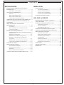
CONTENTS
REV 0 - B - 2006190710
L-C2-607
GETTING STARTED
INSTALLATION, OPERATION, AND SAFETY
INFORMATION �������������������������������������������������������������4
ELECTRICAL CONNECTIONS ������������������������������������4
GAS SAFETY INFORMATION ��������������������������������������5
WARNING ���������������������������������������������������������������5
WHEN USING PROPANE GAS ������������������������������������5
WHEN USING NATURAL GAS ������������������������������������5
INSTALLATION SAFETY GUIDELINES�������������������������5
OPERATING THE UNIT SAFELY AND CORRECTLY ���5
SAFE USE & MAINTENANCE OF PROPANE GAS
CYLINDERS ������������������������������������������������������������������7
GRILL ENCLOSURE / VENTILATION
REQUIREMENTS ����������������������������������������������������������8
ENCLOSURE �����������������������������������������������������������9
WHEN A PROPANE (L.P.) CYLINDER IS USED
IN THE ENCLOSURE
������������������������������������������������9
INSTALLATION REQUIREMENTS �����������������������������10
OVERHEAD CONSTRUCTION AND EXHAUST HOOD
REQUIREMENTS
����������������������������������������������������10
REAR WALL CLEARANCES ��������������������������������������11
BACKSPLASH CLEARANCE (if applicable) �����������������11
SIDE WALL / CORNER WALL CLEARANCES
(if applicable)
���������������������������������������������������������11
COMBUSTION AIR AND COOLING AIRFLOW ������������12
GAS-SUPPLY PLUMBING REQUIREMENTS ���������������12
ELECTRICAL SAFETY �����������������������������������������������13
MODEL SPECIFICATIONS ������������������������������������������14
COUNTERTOP OVERHANG �������������������������������������15
ENCLOSURE VENTILATION ������������������������������������15
SUBSTRATE ����������������������������������������������������������� 16
BUILT-IN GRILL WIRING DIAGRAM �������������������������17
AURORA GRILL REPLACEMENT PARTS LIST ����������18
INSTALLATION
INSTALLATION ����������������������������������������������������������20
COUNTER PREPARATION ���������������������������������������20
CONNECT THE GAS SUPPLY �����������������������������������20
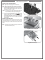
INSTALL THE FLAVOR GRIDS ����������������������������������21
INSTALL THE COOKING GRIDS �������������������������������22
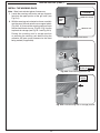
ELECTRICAL INSTALLATION �����������������������������������24
USE, CARE, & SERVICE
IDENTIFICATION OF GRILL CONTROLS ������������������25
USING THE GRILL �����������������������������������������������������26
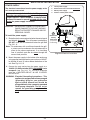
LIGHTING (IGNITION) INSTRUCTIONS ��������������������27
ELECTRONIC LIGHTING ����������������������������������������27
MANUAL LIGHTING �����������������������������������������������27
SHUTTING OFF THE UNIT �������������������������������������� 27
OPTIONAL ROTISSERIE INSTRUCTIONS �����������������29
OPTIONAL INFRARED BURNER OPERATION ����������30
SERVICING AND CLEANING �������������������������������������31
CLEANING YOUR GRILL ����������������������������������������� 31
REPLACING HALOGEN BULBS �������������������������������� 33
CONTROL PANEL REMOVAL �����������������������������������34
SYSTEM RESET ������������������������������������������������������35
BURNER(S) REMOVAL ��������������������������������������������35
CONVERT GAS TYPE / CHECK BURNER ORIFICES ����36
AIR SHUTTER ADJUSTMENT ����������������������������������� 38
NOTES PAGE ��������������������������������������������������������������40
TROUBLESHOOTING ������������������������������������������������� 41
WARRANTY ���������������������������������������������������������������42

4
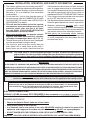
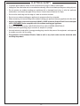
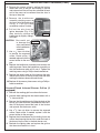
1. The outdoor appliance and surrounding area MUST
remain clear of flammable substances such as gasoline,
yard debris, wood, etc. Maintain a minimum horizontal
clearance of 18" (in all directions) from combustible
materials/items.
2. Do not block the 1" front air inlet along the bottom of
the control panel. See the COMBUSTION AIR AND
COOLING AIRFLOW section under INSTALLATION
REQUIREMENTS for details.
3. This unit must be installed so that the required
vent openings and surrounding area of the unit
enclosure remain clear and free at all times.
See the GRILL ENCLOSURE/VENTILATION
REQUIREMENTS section for details.
4. When using propane gas: the propane cylinder,
regulator, and rubber hose must be in a location
not subject to temperatures above 125° F (51° C).
5. The back burner cover or IR burner cover (if equipped)
must be removed before using the burner.
6. The flames on each burner burn evenly along the
entire burner with a steady flame (mostly blue). If
burner flames are not normal, check and clean the
orifice and burner/venturi tubes for insects and insect
nests. A clogged tube can lead to a fire beneath the
unit. A proper flame pattern will ensure safe operation
and optimal performance. Adjust the air shutter as
needed (see AIR SHUTTER ADJUSTMENT section).
7. The in-line gas valve or gas cylinder valve must always
be shut OFF when the unit is not in use.
8. The drip collector holes must be clear and unobstructed.
Excessive grease deposits can result in a grease fire.
9. Whenever reconnecting any wires, apply a small
amount of dielectric grease to the male connector,
then make the connection. This will ensure conductivity
and prevent moisture from affecting the contact.
10. Wear gloves and use extreme caution whenever
installing and handling this product and its accessories
as certain components have sharp edges that can
cause personal injury.
WARNING: NEVER cover more than 75% of the cooking or grill surface with griddles or pans. Overheating will occur,
and burners will not perform properly when combustion heat is trapped below the cooking surface.
IMPORTANT
IN THE EVENT OF A GREASE FIRE, IMMEDIATELY SHUT OFF THE MAIN GAS VALVE TO THE UNIT. KEEP THE LID
OPEN AND ALLOW THE FIRE TO EXTINGUISH ITSELF. KEEP AT A SAFE DISTANCE. A THOROUGH INSPECTION BY
A QUALIFIED PROFESSIONAL SERVICE TECHNICIAN SHOULD BE CONDUCTED BEFORE FUTURE USE OF YOUR
UNIT. THE SERVICE TECHNICIAN WILL CHECK THE SYSTEM FOR GAS LEAKS AND WILL CHECK ALL ELECTRICAL
WIRING FOR DAMAGE. ALL GAS LEAKS AND WIRING MUST BE REPAIRED PRIOR TO FUTURE USE.
ELECTRICAL CONNECTIONS
A 120VAC (15 AMP minimum) GFCI GROUNDED 3-wire receptacle (not included) is required within
the vicinity of the unit to provide power to it. The GFCI receptacle must be a WEATHER-PROOF IN-USE
COVERED RECEPTACLE.
• Observe the National Electric Code and all local codes.
• Verify proper polarity of the receptacle.
• If an extension cord is used, ensure it is a 3-wire GROUNDED cord that is rated for the power of the
equipment, and is approved for outdoor use with a W-A marking. DO NOT use 2-prong adapters.
• DO NOT TAMPER WITH THE EXTENSION CORD OR THE UNIT POWER-SUPPLY CORD.
Important: ONLY REPLACE THE INTERIOR OVEN LIGHTS WITH 12V / 10 WATT HALOGEN BULB(S).
CAUTION: FOR YOUR SAFETY, you must provide openings in the grill enclosure for replacement air
and ventilation (in case of possible leakage from gas connections or propane cylinders).
Failure to do so may result in a fire or explosion causing property damage, bodily injury,
or death. See the GRILL ENCLOSURE / VENTILATION REQUIREMENTS section for details.
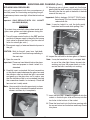
The unit serial number tag can be found affixed to the grill body behind the control panel (on an
aluminum tag) and on the underside of the drip tray handle (on a thermal label). It is recommended
that the drip tray first be removed and cleaned / emptied of its contents, then turned over to view.
The unit rating label is located inside of the control panel.
INSTALLATION, OPERATION, AND SAFETY INFORMATION

5
WARNING
This gas appliance, its enclosure, and the propane cylinder enclosure, if any, MUST be plumbed and vented
in accordance with local building and safety codes and should be approved by local code enforcement
officials. This appliance MUST be installed and operated according to the information below.
FAILURE TO PROPERLY VENT THE GRILL ENCLOSURE MAY RESULT IN A FIRE OR EXPLOSION CAUSING
PROPERTY DAMAGE, BODILY INJURY, OR DEATH.
A leaking gas connection or valve unintentionally left open will create a hazard.
WHEN USING PROPANE GAS
• Propane gas (also known as L.P. gas) is heavier than air and will accumulate or pool in an inadequately
vented enclosure or recessed area.
• If a pool of propane gas is ignited, an explosion will occur. Adequate venting at the floor level, or the lowest
point where gas could accumulate, will eliminate this danger.
Refer to the GRILL ENCLOSURE / VENTILATION REQUIREMENTS section.
Observe all local codes.
• DO NOT store a spare propane-gas cylinder under or near the grill enclosure.
WHEN USING NATURAL GAS
• Natural gas is lighter than air and will accumulate at the top of an inadequately vented enclosure.
• If an accumulation of natural gas is ignited, an explosion will occur. Adequate venting at the top of the
enclosure, or the highest point where gas could accumulate, will eliminate this danger.
Refer to the GRILL ENCLOSURE / VENTILATION REQUIREMENTS section.
Observe all local codes.
INSTALLATION SAFETY GUIDELINES
THIS UNIT MUST BE INSTALLED SO THAT THE REQUIRED VENT OPENINGS AND SURROUNDING AREA
OF THE GRILL ENCLOSURE REMAIN CLEAR AND FREE AT ALL TIMES. See the GRILL ENCLOSURE /
VENTILATION REQUIREMENTS section for details.
CAUTION: FOR YOUR SAFETY, you must provide openings in the grill enclosure for replacement air and
ventilation (in case of possible leakage from gas connections or propane cylinders). Failure
to do so may result in a fire or explosion causing property damage, bodily injury, or death.
See the GRILL ENCLOSURE / VENTILATION REQUIREMENTS section for details.
The gas cylinder, regulator, and rubber hose must be in a location not subject to temperatures above
125° F (51° C).
IF A PROPANE CYLINDER IS INSTALLED INSIDE OF THE GRILL ENCLOSURE, THE GUIDELINES FOUND
IN THE GRILL ENCLOSURE / VENTILATION REQUIREMENTS SECTION MUST BE FOLLOWED.
WHEN OPERATING THIS GAS APPLIANCE, ALL INSTRUCTIONS AND WARNINGS
MUST BE OBSERVED. FAILURE TO DO SO MAY RESULT IN A FIRE OR EXPLOSION
CAUSING PROPERTY DAMAGE, BODILY INJURY, OR DEATH.
Every time you use the unit, make sure that:
1. The area around the grill enclosure is clear and free from combustible materials, gasoline and flammable
vapors/liquids.
2. There is no blockage of the airflow through the vent openings located on the grill enclosure.
3. The hose is inspected (if applicable). See SAFE USE & MAINTENANCE OF PROPANE-GAS CYLINDERS section.
DO NOT store any combustible materials, gasoline, and any other flammable vapors/liquids in the vicinity of the
unit. Provide adequate clearance for servicing and operation.
GAS SAFETY INFORMATION
OPERATING THE UNIT SAFELY AND CORRECTLY

6
U
L
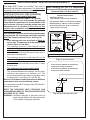
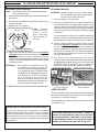
Fig. 6-1 type coupleur de fil de point culminant d’I
Valve
de
décompression
QCC
Type 1
Valve
Ajustage de précision
en laiton de fil de
point culminant
Indicateur
de niveau
de liquide
(facultatif)
Écrou de main avec le
fil de point culminant.
Régulateur
Passage
Tuyau
Volant de commande
main dans le sens des aiguilles d’une montre pour engager les
fils et pour serrer jusqu’à ce que douillettement. L’utilisation des
pinces ou de la clé ne devrait pas être nécessaire. Seulement
le propane marqué par cylindres doit être employé.
Pour débrancher: Tournez l’écrou de main dans le sens
contraire des aiguilles d’une montre jusqu’à isolé (fig. 6-1).
Important: Avant d’employer le unité, et ensuite chaque
fois que le cylindre est enlevé et rattaché,
examinez tous les raccordements pour
déceler les fuites. Arrêtez les valves de unité
et ouvrez la valve principale de cylindre, puis
vérifiez les raccordements avec de l’eau
savonneux. Réparez toutes les fuites avant
d’allumer le unité.
ATTENTION: Tournez toujours la valve principale de cylindre
de propane au loin après chaque utilisation,
et avant de déplacer le unité et le cylindre, ou
débrancher l’accouplement. Cette valve doit
rester fermée et le cylindre a débranché alors
que l’appareil n’est pas en service, quoique
l’écoulement de gaz soit arrêté par un dispositif
de sûreté quand le coupleur est débranché.
Inspectez soigneusement l’ensemble de tuyau chaque fois
avant que le gaz soit allumé. Un tuyau fissuré ou effiloché doit
être immédiatement remplacé.
Si l'appareil est stocké à l'intérieur, le cylindre doit être disconnected
et a enlevé. Des cylindres Disconnected doivent être stockés
dehors, hors de la portée des enfants, avec les prises de valve
filetées étroitement installées, et ne doivent pas être stockés dans
un bâtiment, le garage, ou n'importe quel autre secteur inclus.
POUR VOTRE SÛRETÉ
a. Ne stockez pas un cylindre de gaz disponible de propane
dessous ou ne vous approchez pas de cet appareil.
b. Ne remplissez jamais cylindre au delà de 80 pour cent de
plein.
c. SI L’INFORMATION DANS “A” ET “B” N’EST PAS SUIVIE
EXACTEMENT, UN FEU CAUSANT LA MORT OU DES
DOMMAGES SÉRIEUX PEUT SE PRODUIRE.
IMPORTANT POUR VOTRE SÛRETÉ
LISEZ ET SUIVEZ TOUS LES AVERTISSEMENTS ÉQUIPÉS DE VOTRE CYLINDRE DE GAZ DE PROPANE.
En actionnant cet appareil avec un cylindre de gaz de propane ON DOIT observer ces instructions et avertissements.
LE MANQUE DE FAIRE AINSI PEUT AVOIR COMME CONSÉQUENCE UNE INCENDIE OU UNE EXPLOSION SÉRIEUSE.
CYLINDRE ET CONDITIONS ET
CARACTÉRISTIQUES DE CONNECTEUR
a. Les bouteilles, les vannes et les tuyaux de propane doivent
être entretenus et inspectés avant chaque utilisation. Ils
doivent être remplacés en cas de dommages visibles. Si
le tuyau est coupé ou présente des signes d’abrasion ou
d’usure, il doit être remplacé avant utilisation (voir e.).
b. Cette unité, lorsqu'elle est utilisée avec une bouteille, doit
être connectée à une bouteille standard de gaz propane de
5 gallons (20 lb) équipée d'un dispositif anti-débordement
répertorié. L’appareil est obligatoire sur toutes les bouteilles
vendues depuis le 1er octobre 1998 afin d’empêcher tout
remplissage excessif.
c. Les dimensions du cylindre doivent être d'environ 12 "(30,5 cm)
de diamètre et 18" (45,7 cm) de hauteur. Les bouteilles doivent
être construites et marquées conformément aux spécifications
du ministère des Transports (DOT) pour les bouteilles à gaz LP
ou à la norme relative aux bouteilles, sphères et tubes pour le
transport des marchandises dangereuses et à la Commission,
CAN / CSA-B339, selon le cas.
d. Le cylindre doit inclure un collier pour protéger la valve
de cylindre et le circuit d’alimentation de cylindre doit être
assuré le retrait de vapeur.
e. Le montage du régulateur de pression et le flexible (Fig. 6-1)
fourni avec cet appareil au gaz en plein air (modèles au
propane seulement) doit être utilisé. Assemblées d'origine et
régulateur de pression et le tuyau de remplacement doivent
être ceux spécifiés par le fabricant pour le raccordement d'un
dispositif de cylindre de liaison identifiée comme de type I
par le ANSI Z 21.58/CGA 1.6 (voir liste des pièces pour les
informations de commande).
f. La valve de cylindre de gaz de propane doit être équipée
d’un dispositif d’accouplement de raccordement de
cylindre, décrit comme type I dans la norme définie dans le
e. de paragraphe ci-dessus. Ce dispositif est généralement
décrit comme coupleur de fil de point culminant.
g. Si votre cylindre de gaz de propane vient avec une prise
de la poussière, placez le bouchon anti-poussière sur la
sortie de valve de cylindre toutes les fois que le cylindre
n’est pas en service.
OPÉRATION DE COUPLEUR
Pour relier le regulator/hose à l’ajustage de précision de
valve de cylindre de gaz de propane: Serrez l’écrou de main
sur le régulateur au-dessus de l’ajustage de précision de fil
de point culminant sur la valve de cylindre. Tournez l’écrou de
1
2
3
4
e. Le régulateur de pression et l’ensemble de tuyau utilisé
doivent assortir les spécifications pour le type I par ANSI
Z 21.58/CGA 1.6 (voir la figue. 6-1).
Pour les besoins de ventilation et d'enceinte au propane,
Voir la section GRILL ENCLOSURE / VENTILATION REQUIREMENTS.
UTILISATION SÛRE ET ENTRETIEN DES CYLINDRES DE GAZ DE PROPANE

7
U
L
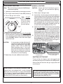
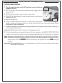
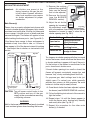
Fig. 7-1 Type I Acme thread coupler
Pressure
relief
valve
QCC
Type 1
valve
Brass Acme
thread fitting
Liquid level
indicator
(optional)
Hand nut with Acme
thread
Regulator
Vent
Hose
Hand wheel
The use of pliers or a wrench should not be necessary. Only
cylinders marked “propane” may be used.
To disconnect: Turn the hand nut counterclockwise until
detached (Fig. 7-1).
Important: Before using the unit, and after each time
the cylinder is removed and reattached,
check the hose for wear (see a.) and check
all connections for leaks. Turn off the unit
valves and open the main cylinder valve,
then check connections with soapy water.
Repair any leaks before lighting the unit.
CAUTION: Always turn the propane cylinder main valve
off after each use, and before moving the unit
and cylinder or disconnecting the coupling.
This valve must remain closed and the
cylinder disconnected while the appliance
is not in use, even though the gas flow is
stopped by a safety feature when the coupler
is disconnected.
Carefully inspect the hose assembly each time before the
gas is turned on. A cracked or frayed hose must be replaced
immediately.
If the appliance is stored indoors, the cylinder must be
disconnected and removed. Disconnected cylinders must be
stored outdoors, out of the reach of children, with threaded
valve plugs tightly installed, and must not be stored in a
building, garage, or any other enclosed area.
FOR YOUR SAFETY
a. DO NOT store a spare propane-gas cylinder under or
near this appliance.
b. NEVER fill the cylinder beyond 80-percent full.
c. IF THE INFORMATION IN a. AND b. IS NOT FOLLOWED
EXACTLY, A FIRE CAUSING DEATH OR SERIOUS
INJURY MAY OCCUR.
IMPORTANT FOR YOUR SAFETY
READ AND FOLLOW ALL WARNINGS PROVIDED WITH THE PROPANE-GAS CYLINDER.
When operating this appliance with a propane-gas cylinder, these instructions and warnings MUST be observed.
FAILURE TO DO SO MAY RESULT IN A SERIOUS FIRE OR EXPLOSION.
CYLINDER/CONNECTOR REQUIREMENTS
a. Propane-gas cylinders, valves, and hoses must be
maintained in good condition and inspected before each use
of appliance. They must be replaced if there is any visible
damage. If hose is cut or shows excessive abrasion or wear,
it must be replaced before using appliance (see e.).
b. This unit, when used with a cylinder, should be connected
to a standard 5-gallon (20 lb.) propane-gas cylinder
equipped with a listed overfilling prevention device. The
device has been required on all cylinders sold since
October 1,1998, to prevent overfilling.
c. Cylinder dimensions should be approximately 12" (30.5
cm) in diameter and 18" (45.7 cm) high. Cylinders must
be constructed and marked in accordance with the U.S.
Department of Transportation (D.O.T.) Specifications for
LP-Gas Cylinders, or the Standard for Cylinders, Spheres,
and Tubes for Transportation of Dangerous Goods and
Commission, CAN/CSA-B339, as applicable.
d. The cylinder used must include a collar to protect the
cylinder valve, and the cylinder supply system must be
arranged for vapor withdrawal.
e. The pressure regulator and hose assembly (Fig. 7-1)
supplied with this outdoor gas appliance (L.P. models
only) must be used. Original and replacement pressure
regulator and hose assemblies must be those specified by
the manufacturer for connection with a cylinder connecting
device identified as Type I by the ANSI Z 21.58/CGA 1.6
(see PARTS LIST for ordering information).
f. The propane-gas cylinder valve must be equipped with
a cylinder connection device, described as Type I in the
standard defined in paragraph e. above. This device is
commonly described as an Acme thread coupler.
g. If the propane-gas cylinder comes with a dust plug, place
the dust cap on the cylinder valve outlet whenever the
cylinder is not in use.
COUPLER OPERATION
To connect the regulator/hose assembly to the propane-
gas cylinder valve fitting: Press the hand nut on the regulator
over the Acme thread fitting on the cylinder valve. Turn the hand
nut clockwise to engage the threads and tighten until snug.
e. The pressure regulator and hose assembly used must
match the specification for Type I by ANSI Z 21.58/CGA
1.6 (see Fig. 7-1).
For propane ventilation and enclosure requirements,
see the GRILL ENCLOSURE / VENTILATION REQUIREMENTS section.
SAFE USE & MAINTENANCE OF PROPANE GAS CYLINDERS

8
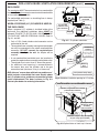
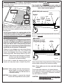
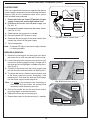
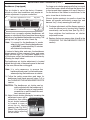
Fig. 8-1 Ventilation detail
Min.
90˚
Ventilation Requirements:
• Minimum 4 openings
(2 per side wall - spaced at min. 90 degrees)
• Top openings: within 5" of countertop (see below)
• Bottom openings: within 5" of floor (see below)
• Each vent opening: min. 10 sq. in. of free area
(Total = 40 sq. in. free area)
1"
max.
Keep surrounding
area and vent
openings clear and
free at all times.
5"
max.
1"
max.
5"
max.
Vent openings (4)
10 sq. in. of free
area min. (each)
(Total = 40 sq. in.)
Note: Vent openings example shown. Your design may vary.
• 6" min. clearance between all vent openings
and any items outside of enclosure
• 2" min. clearance between all vent openings
and any items within enclosure
Fig. 8-2 Vent openings clearance
2"
min.
(Side View)
6"
min.
Vent
opening
When installing this unit in a combustible
enclosure, an RHP insulating liner must be used.
Reference Table 1 for liner model #.
Fire Magic GFRC islands are available. They meet all
enclosure and ventilation requirements. For requirements
regarding custom-built enclosures, see below.
VENTILATION (ALL ENCLOSURES)
For All Piping Systems and All Gas Types:
(Natural Gas, Household Propane, L.P. Cylinder)
FOR YOUR SAFETY, you must provide the openings
listed below for replacement air and ventilation of the
grill enclosure (in case of possible leakage from gas
connections or L.P. cylinders). Failure to do so may
result in a fire or explosion causing property damage,
bodily injury, or death.
One side of the enclosure shall be left completely open
to the outside; OR 4 (minimum) ventilation openings
MUST be created (reference Fig. 8-1 and Fig. 8-2):
• Each opening must have a minimum of 10 sq. in.
of free area. The openings must be equally sized.
(Total of 40 sq. in. free area.)
• Two openings must be in the side walls of the
enclosure, at the top level, and spaced at a minimum
of 90 degrees. The openings must begin 1" or less
below the countertop level and end no more than 5"
below the countertop level.
• Two openings must be in the side walls of the
enclosure, at the floor level, and spaced at a minimum
of 90 degrees. The openings must begin 1" or less
above the floor level and end no more than 5" above
the floor level.
• The openings must remain unobstructed:
The clearance between the openings and any items
outside of the enclosure is a minimum of 6". The
clearance between the openings and any items within
the enclosure is a minimum of 2". See Fig. 8-2.
When an L.P. cylinder is used in the enclosure, additional
requirements exist, see the following section.
It is acceptable to use RHP venting panels (PN 5510-01).
Contact your dealer.
KEEP THE REQUIRED VENT OPENINGS AND
SURROUNDING AREA OF THE ENCLOSURE CLEAR
AND FREE AT ALL TIMES.
WARNING: Ventilation openings in side walls shall not
communicate directly with other enclosures
of the outdoor cooking gas appliance.
GRILL ENCLOSURE / VENTILATION REQUIREMENTS

9
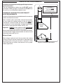
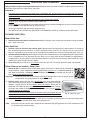
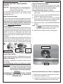
Fig. 9-3 Optional door w/ tank tray & louvers
Cylinder & regulator/hose assembly
protected by heatshield
Additional adapters may be required
for your setup (not included)
Equipped with
adapter for hose
assembly.
Flex connector
not included.
Fig. 9-2 Additional ventilation opening for L.P. cylinder
RHP DOOR MEETS ALL REQUIREMENTS ABOVE
Access
door
L.P.
cylinder
Ventilation
opening
(at cylinder gas
connection level,
min. 10 sq. in
free area)
(L.P. Cylinder setups only)
Louvers
Tray
ENCLOSURE
The countertop MUST be constructed of non-combustible
materials. The enclosure can be constructed of combustible
or non-combustible materials.
For combustible enclosures, an insulating liner is always
required (see Table 1).
WHEN A PROPANE (L.P.) CYLINDER IS USED IN
THE ENCLOSURE
When a propane (L.P.) cylinder is installed inside of the
enclosure, the additional guidelines below MUST be
followed. FAILURE TO DO SO MAY CAUSE DAMAGE
TO YOUR UNIT AND/OR PERSONAL INJURY. Refer to
Fig. 9-1 and 9-2.
• Only a C.S.A. listed stainless steel connector can be
connected to the unit.
• The regulator/hose assembly coming from the cylinder
can only be connected to the above mentioned flex
connector. DO NOT connect the regulator/hose
assembly directly to the unit. An adapter will be
required.
• A non-combustible heatshield must be installed to
protect the regulator/hose assembly and cylinder valve.
• The cylinder must rest at least 2" above the ground.
• An additional vent opening is recommended in
the access door near the cylinder and at the gas
connection level (minimum 10 sq. in. of free area).
RHP offers an "access door with tank tray and louvers"
which includes a heatshield that rests directly above
the L.P. cylinder, a tray, and louvers to meet the cylinder
install requirements. The door is shown in Fig. 9-3.
Contact your dealer for ordering information.
Adapter
C.S.A. listed
stainless steel
flex connector
Non-combustible
heatshield
Regulator/
hose
assembly
L.P.
cylinder
3" min.
2" min.
from ground
Fig. 9-1 L.P cylinder orientation
GRILL ENCLOSURE / VENTILATION REQUIREMENTS (cont.)

10
Installation must be performed by a qualified professional
service technician.
This unit is designed for outdoor use only. DO NOT use this
unit inside a building, garage, or enclosed area. DO NOT use
this unit in or on a recreational vehicle or boat.
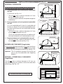
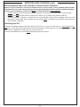
OVERHEAD CONSTRUCTION AND EXHAUST
HOOD REQUIREMENTS
A minimum 5 foot clearance is required between the countertop
and the overhead construction.
When installed under combustible overhead construction,
the area above the cooking surface of the unit must be
covered with an exhaust hood. The exhaust hood provides
the protection for the combustible overhead construction.
See exhaust hood information below and Fig. 10-1.
Important: DO NOT use this appliance under unprotected
combustible overhead construction.
When installed under overhead non-combustible construction,
an exhaust hood is highly recommended; see exhaust hood
information below and Fig. 10-1.
Exhaust Hood
When using an exhaust hood, the area above the cooking
surface of the grill must be covered with a hood larger than
the cooking area of the grill, and with a minimum of 1200
CFM (cubic feet per minute) rated exhaust fan for proper
outdoor application.
INSTALLATION REQUIREMENTS
Fig. 10-1 Overhead requirements
Min.
5'
OVERHEAD CONSTRUCTION
EXHAUST
HOOD
Combustible overhead
construction:
Exhaust hood required
Non-combustible
overhead construction:
Exhaust hood highly recommended
N
O
N
C
O
M
B
U
S
T
I
B
L
E
W
A
L
L

11
REAR WALL CLEARANCES
For the minimum clearances between the unit and rear walls,
your setup must fall within one (or more) of the following:
A. Clearance between unit and strictly non-combustible
rear wall
(i.e. brick wall, see Fig. 11-1)
• The unit must have a minimum clearance of 4" from
the non-combustible rear wall.
(To allow for proper ventilation and prevent dangerous
overheating.)
B. Clearance between unit and a protected combustible
rear wall
(i.e. a non-combustible wall in front of a combustible wall
to serve as a barrier. This can be accomplished by brick,
or a metal stud finished with non-combustible substrate,
see Fig. 11-2)
• The unit must have a minimum clearance of 14" from
the protected combustible rear wall.
(The 4" non-combustible material plus an additional 10"
clearance between the unit and protected rear wall.)
C. Clearance between unit and combustible rear wall
• The unit must have a minimum clearance of 18" from
the combustible rear wall (see Fig. 11-3).
BACKSPLASH CLEARANCE (if applicable)
If a non-combustible backsplash exists, it must have a minimum
of a 4" clearance from the rear of the unit (to allow for proper
ventilation and prevent dangerous overheating). See Fig. 11-4.
Important: This 4" backsplash clearance must first be met
prior to any non-combustible walls beginning
behind it.
SIDE WALL / CORNER WALL CLEARANCES
(if applicable)
The unit must have a minimum clearance of 24" from any
side walls (to account for variables in airflow that could affect
performance). See Fig. 11-5.
INSTALLATION REQUIREMENTS (Cont.)
Fig. 11-1 Clearance 'A' Diagram
Fig. 11-2 Clearance 'B' Diagram
Fig. 11-3 Clearance 'C' Diagram
Non-combustible
Min.
4"
Min.
14"
Non-combustible
substrate
Non-combustible 4"
Combustible
Min.
18"
Fig. 11-4 Backsplash clearance
Non-combustible
Backsplash
Min.
4"
Com-
bustible
(Clearance required
for rear wall)
(Clearance required
for rear wall)
(Clearance required
for rear wall)
Fig. 11-5 Side/corner wall clearance
Min.
24"
Clearances continued on following page

12
CONTROL PANEL CLEARANCES
• The control panel MUST have a minimum side
clearance of 6" from any obstructions/side walls. See
Fig. 12-1.
(To allow for access to light switch and control panel
removal.)
• The control panel MUST remain removable for
servicing (see CONTROL PANEL REMOVAL section).
Any adjacent countertops must not obstruct the panel
from being removed.
COMBUSTION AIR AND COOLING AIRFLOW
Proper airflow (front-to-back, Fig. 12-2) MUST be maintained
for the unit to perform as it was designed. If airflow is blocked,
overheating and poor combustion will result. Do not block the
1" front air inlet along the bottom of the control panel.
CAUTION: Wind blowing into or across the rear oven lid
vent (Fig. 12-4) can cause poor performance
and/or dangerous overheating. Install the grill
so that the prevailing wind blows toward the
front of the grill (Fig. 12-3). A wind deflector
is available for purchase to assist in proper
airflow during windy conditions. See Table
1 for model numbers. Follow the instructions
included with the wind deflector for installation.
GAS-SUPPLY PLUMBING REQUIREMENTS
For natural gas or a household propane system, rigid
1
/
2
" or
3
/
4
" black steel pipe or local code-approved pipe is required
to conduct the gas supply to the unit. Contact your local gas
supplier. Connect this pipe to the required C.S.A.-approved
stainless-steel flex connector (attached). An NPT adapter
has been provided for
1
/
2
" pipe. DO NOT use a rubber hose
within the unit enclosure. Apply only joint compounds that
are resistant to all gasses on all NPT pipe fittings except flare
fittings. Make sure to tighten all fittings securely.
Note: If
1
/
2
" pipe is used with natural gas, it should be
no longer than 20'.
Important: A shut-off valve (not included) in the gas
line is required. It provides for safety when
the unit is not in use and for convenient
maintenance and repair. It must be installed
within 6 feet of the unit. If it is located within
the enclosure, it must be easily accessible.
Use a pipe joint compound resistant to
all gasses on all male fittings except flare
fittings.
GAS SUPPLY AND MANIFOLD PRESSURES:
For natural gas - normal 7" water column (w.c.), minimum
5", maximum 10
1
/
2
". For propane gas - normal 11" w.c.,
minimum 10", maximum 13".
INSTALLATION REQUIREMENTS (Cont.)
CORRECT
PLACE GRILL SO PREVAILING
WIND BLOWS TOWARD FRONT
OF GRILL
Fig. 12-3 Airflow direction - CORRECT
(1" front air inlet)
Fig. 12-2 Airflow diagram
YOU MUST PROTECT
REAR OVEN VENT FROM
PREVAILING WIND
Rear oven lid vent
INCORRECT
Fig. 12-4 Airflow direction - INCORRECT
Fig. 12-1 Control panel clearances
Min.
6"
Min.
6"

13
• To protect against electric shock, do not immerse cord or plugs in water or other liquid.
• Unplug from the outlet when not in use and before cleaning. Allow to cool before putting on or taking off parts.
• Do not operate any outdoor cooking gas appliance with a damaged cord, plug, or after the appliance
malfunctions or has been damaged in any manner. Contact the manufacturer for repair.
• Do not let the cord hang over the edge of a table or touch hot surfaces.
• Do not use an outdoor cooking gas appliance for purposes other than intended.
• When connecting, first connect plug to the outdoor cooking gas appliance then plug appliance into the outlet.
• Use only a properly wired and inspected 120VAC (15 AMP minimum) Ground Fault Circuit Interrupter
(GFCI) GROUNDED 3-wire receptacle with this outdoor cooking gas appliance.
• The GFCI receptacle must be a WEATHER-PROOF IN-USE COVERED RECEPTACLE.
• Never remove the grounding plug or use with an adapter of 2 prongs.
• Use only extension cords with a 3 prong grounding plug, rated for the power of the equipment, and approved
for outdoor use with a W-A marking.
• The provisions of the National Electric Code as well as any local codes must be observed when
installing the product.
ELECTRICAL SAFETY

14
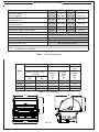
MODEL SPECIFICATIONS
A430i A540i A660i A790i
Main burner quantity
N/P orifice drill size
2
#42 / #54
3
#44 / #55
3
#42 / #54
3
#38 / #53
Backburner
▲
N/P orifice drill size
#52 / #59 #48 / #56 #48 / #56 #45 / #55
Infrared searing burner
▲
N/P orifice drill size
#49 / #56 #49 / #56 #45 / #55 #45 / #55
Aurora insulating liner model # (not included)* 23130-52 23150-52 3176-52 3186-52
Wind deflector model # (not included) 23728-19 23732-20 23732-20 23745-20
Burner maintenance kit model # (not included) MK-1
Grill complete maintenance kit model # (not included) MCK-1
Input electrical requirements 100~240 VAC / 1.90A max. / 50/60 Hz / GFCI outlet
Electrical output 13 VDC / 150 Watts
Interior oven lights rating 12V / 10 watt halogen bulb
▲
If equipped
* Note: If installing this grill in a combustible enclosure, the correct insulating liner must be used. Consult liner instructions for counter
cutout dimensions and installation.
Model
Height Width Depth
(Top to bottom) (Left to right) (Front to
back)
Bottom of hanger to top
(with oven)
Maximum
width
(C)
Control
panel
width
(D)
Maximum
depth
(E)
Open
(A)
Closed
(B)
A430i
21
1
/4" 13
3
/4" 27" 26" 26"
A540i
21
1
/4" 13
3
/4" 33
1
/2" 32
1
/2" 26"
A660i
24
1
/2" 15
1
/2" 33" 32
1
/2" 30
1
/2"
A790i
24
1
/2" 15
1
/2" 38
3
/4" 38
1
/4" 30
1
/2"
E
B
A
C
D
Fig. 14-3
Table 1 - Product Specifications
Table 2 - Grill Dimensions

15
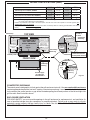
MODEL SPECIFICATIONS (cont.)
COUNTERTOP OVERHANG
The control panel is designed to sit flush against the grill enclosure front wall. If the non-combustible enclosure
countertop extends beyond the front wall, creating a countertop overhang, it must be cut flush with the front wall
for the width of the control panel or a gap will be created exposing the forward portions of the left and right side
grill fire walls. See illustrations above.
ENCLOSURE VENTILATION
FOR YOUR SAFETY, you must provide openings in the grill enclosure for replacement air and ventilation (in
case of possible leakage from gas connections or propane cylinders). Failure to do so may result in a fire or
explosion causing property damage, bodily injury, or death. See the GRILL ENCLOSURE / VENTILATION
REQUIREMENTS section for details.
TOP VIEW
Countertop
Lower
support
Countertop
overhang
Control panel
NON-COMBUSTIBLE
GRILL ENCLOSURE
CUTOUT DIMENSIONS
Fig. 15-1
FRONT VIEW
B
C
D
See next page
for substrate
considerations
Countertop
overhang
X
TOP VIEW
SIDE VIEW
Countertop
overhang
(Control
panel)
(Countertop)
Y
1
/
4
"
Clearance
(Overhang)
X= D-B÷2
Y= Total
Countertop
Overhang
A
Control
panel
Check clearance for
control panel removal
2
3
/4"
2
3
/4"
4"4"
1
1
/2" ø or 1
1
/2"
square hole for
electrical supply
1
1
/2" ø or
1
1
/2" square
hole for gas
supply
A430i A540i A660i A790i
A Countertop to unit bottom cutout* 11
1
/
2
" 11
1
/
2
" 11
1
/
2
" 11
1
/
2
"
B Side to side non-combustible cutout* 25
1
/
2
" 32" 31
1
/
4
" 37"
C Front to back non-combustible cutout*† 19
1
/
2
" 19
1
/
2
" 23
1
/
2
" 23
1
/
2
"
D Control panel width non-combustible cutout‡ 26
1
/
2
" 33" 33" 38
3
/
4
"
* Note: If installing this grill in a combustible enclosure, the correct insulating liner must be used. Consult liner instructions
for counter cutout dimensions and installation.
†
Includes any substrate at front wall of enclosure (in the area the rear of the control panel is to sit flush against). See
SUBSTRATE section on next page.
‡
Only applicable for non-combustible enclosures that have countertops with an overhang (see illustration and section
below).
Table 3 - Cutout Dimensions

16
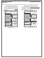
MODEL SPECIFICATIONS (cont.)
SUBSTRATE
When adding any substrate to the grill enclosure front wall (including tiles, stone, etc.), consider the following:
Substrate Behind Control Panel
Substrate Alongside Control Panel
C
C
Flush
(Control panel)
(Countertop)
(Countertop)
(Control panel)
Substrate
(includes tiles,
etc. at front of
enclosure)
Countertop
overhang
(if applicable)
Flush
Grill liner
Grill liner
Substrate
(includes tiles,
etc. at front of
enclosure)
1
/
4
"
Clearance
Any additional substrate alongside the control panel
does not need to be considered in Dim. C (see previous
page), however a
1
/4" clearance on each side (same as
overhang) and below is required.
Substrate
+
countertop "front to back" cutout
must equate to Dim. C (see previous page)
when the substrate sits flush behind the
control panel.
Fig. 16-1 Fig. 16-2
Countertop
overhang
(if applicable)
1
/
4
"
Clearance
TOP VIEW TOP VIEW

17
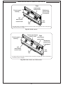
MODEL SPECIFICATIONS (cont.)
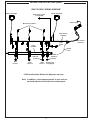
Note: In addition, a wire diagram specific to your unit can
be found affixed to the inside of the control panel.
Power supply
Wire harness
extension
Wire harness
assembly
Valve
manifold
Ground
wire
Main burner igniters
Back burner igniter
(if equipped)
Light
switch
Back burner
(if equipped)
Main
burner 1
Main
burner 2
Main
burner 3
*
A790i model shown. Model wire diagrams may vary.
BUILT-IN GRILL WIRING DIAGRAM
*
LED disk
(large)
LED disk
(small)
Interior oven light
Interior oven light

18
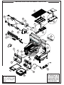
To order replacement
parts, contact your
local Fire Magic
®
dealer.
Some items shown
are optional, or are
not available for
certain models. Your
model may vary, refer
to parts list table.
1
2
3
6
9
10
11
12
16
19
23
27
8
20
18
17
7
14
13
22
41
28
15
5
4
47
21
25
24
AURORA GRILL REPLACEMENT PARTS LIST
36
37

19
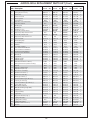
A430i A540i A660i A790i
Item Description
Part No. Qty. Part No. Qty. Part No. Qty. Part No. Qty.
1.
Stainless cooking grid (set of 2 or 3) 3542-DS-2 1 23543-DS-3 1 3544-DS-3 1 3539-DS-3 1
2.
Flavor grid (set of 2 or 3) 3063-S-2 1 3064-S-3 1 3070-S-3 1 3071-S-3 1
3.
Main burner 3042-50 2 3042-50 3 3041-50 3 3041-50 3
4.
Flame arrester kit 24177-05 2 24177-05 3 24177-05 3 24177-05 3
5.
Silicone gasket 24177-06 2 24177-06 3 24177-06 3 24177-06 3
6.
Infrared burner * 3065 1 3065 1 3056 1 3056 1
7.
Oven lid w/ oven thermometer 23729-60 1 23733-60 1 23738-60 1 23745-60 1
or
Oven lid w/ window N/A N/A 24170-56 1 24180-56 1
8.
Warming rack 3672S-B 1 3673S-B 1 3673S-B 1 3675S-B 1
9.
Backburner* 24130-11H 1 24170-11H 1 24170-11H 1 24180-11H 1
10.
Backburner cover* 24148-010 1 24739-010 1 24739-010 1 24745-010 1
11.
Heavy-duty rotisserie motor* 3600-02 1 3600-02 1 3600-02 1 3600-02 1
12.
Super heavy-duty rotisserie motor* N/A N/A 1 3600-05 1 3600-05 1
13.
Heavy-duty rotisserie rod* 3603-30 1 3606-30 1 3606-30 1 N/A
14.
Super heavy-duty rotisserie rod* N/A N/A 1 3606-40 1 3609-40 1
15.
Rotisserie knob* 24187-16 1 24187-16 1 24187-16 1 24187-16 1
16.
Meat holder (pair)* 3613 1 3613 1 3613 1 3613 1
17.
Counterbalance* 3620E 1 3620E 1 3620E 1 3620E 1
18.
Grid lifter 3519 1 3519 1 3519 1 3519 1
19.
Convertible regulator PR-4 1 PR-4 1 PR-4 1 PR-4 1
20.
Valve manifold w/ backburner 24130-22 1 24170-22 1 24170-22 1 24180-22 1
or
valve manifold w/o backburner 24130-28 1 24170-28 1 24170-28 1 24180-28
21.
Control panel w/ backburner 24130-49 1 24170-49 1 24170-49 1 24180-49 1
or
Control panel w/o backburner
24130-50 1 24170-50 1 24170-50 1 24180-50 1
22.
Small knob* 24182-42 1 24182-42 1 24182-42 1 24182-42 1
23.
Large knob 24182-41 2 24182-41 3 24182-41 3 24182-41 3
24.
LED disk (small)* 24182-64 1 24182-64 1 24182-64 1 24182-64 1
25.
LED disk (large) 24182-63 2 24182-63 3 24182-63 3 24182-63 3
26.
Oven lid thermometer w/ bezel † 23307 1 23307 1 23307 1 23307 1
or
Grill top thermometer (window models) † 3573 1 3573 1 3573 1 3573 1
27.
Drip tray 3084 1 3084 1 3084 1 3084 1
or
Drip tray w/ match holder 3085 1 3085 1 3085 1 3085 1
28.
Drip tray liner (set of 4) 3557 1 3557 1 3557 1 3557 1
29.
Wire harness assembly † 24177-29 1 24177-29 1 24177-29 1 24177-29 1
30.
Backburner electrode *† 4199-52 1 4199-52 1 4199-52 1 4199-52 1
31.
Main burner electrode † 3199-72 2 3199-72 3 3199-72 3 3199-72 3
32.
Natural gas orifice(s) † 3001-42-2 1 3001-44-3 1 3001-42-3 1 3001-38-3 1
33.
Natural backburner gas orifice(s) † 3001-52-1 1 3001-48-1 1 3001-48-1 1 3001-45-1 1
34.
Propane gas orifice(s) † 3001-54-2 1 3001-55-3 1 3001-54-3 1 3001-53-3 1
35.
Propane backburner gas orifice(s) † 3001-59-1 1 3001-56-1 1 3001-56-1 1 3001-55-1 1
36.
Power supply w/ cord 24182-18 1 24182-18 1 24182-18 1 24182-18 1
37.
Wire harness extension 24182-53 1 24182-53 1 24182-53 1 24182-53 1
38.
12V / 10 watt halogen light bulb † 24187-15 2 24187-15 2 24187-15 2 24187-15 2
39.
Light lens † 24187-26 2 24187-26 2 24187-26 2 24187-26 2
40.
Lamp assembly † 24187-28 2 24187-28 2 24187-28 2 24187-28 2
41.
Light switch 24182-48 1 24182-48 1 24182-48 1 24182-48 1
42.
Magic View window (only) *† N/A N/A 24187-45 1 24187-45 1
43.
Lighting tube (left) † 24187-29 1 24187-29 1 24187-65L 1 24187-65L 1
44.
Lighting tube (center) † N/A N/A 24187-65C 1 24187-65C 1
45.
Lighting tube (right) † 24187-35 1 24187-35 2 24187-65R 1 24187-65R 1
46.
Backburner flex connector *† 3030-01 1 3030-01 1 3030-08 1 3030-08 1
47.
Air baffle 24194-40 1 24194-40 1 24194-41 1 24194-41 1
*
If equipped † Not shown
AURORA GRILL REPLACEMENT PARTS LIST (Cont.)

20
It is not required to remove the control panel or knobs to
install this unit.
DO NOT lift the unit from the control panel when installing.
COUNTER PREPARATION
Consult Table 3 for non-combustible enclosure cutout dimensions.
An RHP insulating liner must be used if any supporting construction
is combustible. Consult the instructions that come with the liner for
dimensions and additional installation information before beginning
the installation.
This outdoor built-in grill must be supported by the stainless-steel
hanger extending from the upper portion of the grill. The hanger
rests on the left, right, and back of the countertop and on the two
front support adjustment screws located below the control panel on
the left and right sides (see adjustment screw on following page).
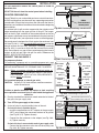
The control panel is designed to sit flush against the enclosure front
wall (see Fig. 20-1). If the non-combustible enclosure countertop
extends beyond the front wall, creating a countertop overhang
(see Fig. 20-2), it must be cut flush with the front wall for the width
of the control panel or a gap will be created exposing the forward
portions of the left and right side grill fire walls. Reference the
MODEL SPECIFICATIONS section.
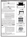
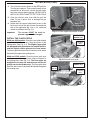
CONNECT THE GAS SUPPLY
For propane cylinders:
For connecting a propane unit to a portable propane tank, read
the safety warnings and follow the instructions in the section SAFE
USE AND MAINTENANCE OF PROPANE GAS CYLINDERS.
Note: When a propane cylinder is installed inside of
the enclosure, the guidelines found in the GRILL
ENCLOSURE / VENTILATION REQUIREMENTS
section MUST be followed.
For household propane or natural gas units:
CAUTION: Use only C.S.A. listed stainless-steel flex connectors
within the enclosure.
WARNING
A rubber or plastic connector will rupture or leak, resulting
in an explosion or serious injury if used inside the appliance
enclosure.
1. Run the attached flex connector routed under the left side of
the grill to the gas supply stub.
2. Turn OFF the gas supply at the source.
3. A shut-off valve is required within 6 feet of the unit.
If shut-off valve is installed in-line:
• Install the supplied flare-to-NPT adapter to the gas supply
(NPT) using a pipe joint compound resistant to all gasses
(see Fig. 20-3, A). Tighten securely.
• Connect the flex connector to the adapter (see Fig. 20-3,
A). Tighten securely.
If shut-off valve is connected to end of gas supply stub:
• Connect the flex connector to the shut-off valve (flare) (see
Fig. 20-3, B). Tighten securely.
INSTALLATION
IDEAL
Flush-mounted
control panel
Countertop
Overhang
Fig. 20-1 Countertop overhang - correct cutout
CORRECT
INSTALLATION
GAP CREATED
Proposed cut-
out in overhang
Countertop
Control panel
stops here
INCORRECT
Fig. 20-2 Countertop overhang - incorrect cutout
Fig. 20-3 Connecting to a gas line
Gas supply
(NPT)
Flex
connector
(from grill)
Flare-to-NPT
shut-off
valve*
(end of gas
supply)
NPT-to-NPT
shut-off
valve*
(in-line)
Gas supply
(NPT)
Flare-to-NPT
adapter
Flex
connector
(from grill)
* Shut-off valve: required, not included, must
be within 6 feet of unit
A B
-OR-
Fig. 20-4 Household LP & Nat. gas diagram
Hanger
Flex
connector
Flare-
to-NPT
adapter
gas supply
(NPT)
OFF
Gas supply
Shut-off valve (shown in-line)
must be within 6 feet of the unit
(Cutout)
La page est en cours de chargement...
La page est en cours de chargement...
La page est en cours de chargement...
La page est en cours de chargement...
La page est en cours de chargement...
La page est en cours de chargement...
La page est en cours de chargement...
La page est en cours de chargement...
La page est en cours de chargement...
La page est en cours de chargement...
La page est en cours de chargement...
La page est en cours de chargement...
La page est en cours de chargement...
La page est en cours de chargement...
La page est en cours de chargement...
La page est en cours de chargement...
La page est en cours de chargement...
La page est en cours de chargement...
La page est en cours de chargement...
La page est en cours de chargement...
La page est en cours de chargement...
La page est en cours de chargement...
-
 1
1
-
 2
2
-
 3
3
-
 4
4
-
 5
5
-
 6
6
-
 7
7
-
 8
8
-
 9
9
-
 10
10
-
 11
11
-
 12
12
-
 13
13
-
 14
14
-
 15
15
-
 16
16
-
 17
17
-
 18
18
-
 19
19
-
 20
20
-
 21
21
-
 22
22
-
 23
23
-
 24
24
-
 25
25
-
 26
26
-
 27
27
-
 28
28
-
 29
29
-
 30
30
-
 31
31
-
 32
32
-
 33
33
-
 34
34
-
 35
35
-
 36
36
-
 37
37
-
 38
38
-
 39
39
-
 40
40
-
 41
41
-
 42
42


Fire Magic Aurora Built-In Grill Manuel utilisateur
- Catégorie
- Barbecues
- Taper
- Manuel utilisateur
dans d''autres langues
Documents connexes
-
Fire Magic Aurora Portable Grill Manuel utilisateur
-
Fire Magic Choice Single and Double Sideburner Manuel utilisateur
-
-
-
-
Fire Magic Gourmet Single and Double Searing Station Manuel utilisateur
-
-
-
-
Fire Magic A660I6LANW Guide d'installation
Autres documents
-
AOG Post Patio Mount Grill Manuel utilisateur
-
-
-
-
-
Primo PGGXLH Le manuel du propriétaire
-
Primo 200 Le manuel du propriétaire
-
FireMagic 32874-1(P) Installation And Operating Insctruction Manual
-
Jackson Grills 2017/18 LUX 550 BI Manuel utilisateur
-