
V4.0 8536625
Please read and understand all instructions before use. Retain this manual for
future reference.
User Manual
Compact Floor
Metal Bender

8536625 Compact Floor Metal Bender V4.0
2 For technical questions call 1-800-665-8685
SPECIFICATIONS
Dies 1, 1-1/4, 1-1/2 (2), 1-3/4, 2, 2-1/2, 3 in.
Max. Stock Thickness 5/16 in.
Mild Steel Capacity (Thickness x Width) 5/16 x 1-1/4 or 1/4 x 2
Round or Square Solid Rod Capacity 5/8 in.
Handle Length 44 in.
Base 10 in. square with four 1/2 in. mounting holes
Overall Height 38 in.
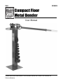
INTRODUCTION
The Compact Floor Metal Bender is designed for bending solid metal stock. Set
to an ideal height for manual bending, it can be used either as a portable or
stationary tool. There are eight different bending dies ranging from 1 to 3 inches
to help make standard or unique metal parts.
SAFETY
WARNING! Read and understand all instructions before using this tool. The
operator must follow basic precautions to reduce the risk of personal injury
and/or damage to the equipment.
Keep this manual for safety warnings, precautions, operating or inspection and
maintenance instructions.
HAZARD DEFINITIONS
Please familiarize yourself with the hazard notices found in this manual. A notice
is an alert that there is a possibility of property damage, injury or death if certain
instructions are not followed.
Compact Floor
Metal Bender

V4.0 Compact Floor Metal Bender 8536625
Visit www.princessauto.com for more information 3
DANGER! This notice indicates an immediate and specific hazard that will
result in severe personal injury or death if the proper precautions
are not taken.
WARNING! This notice indicates a specific hazard or unsafe practice that
could result in severe personal injury or death if the proper
precautions are not taken.
CAUTION! This notice indicates a potentially hazardous situation that may result
in minor or moderate injury if proper practices are not taken.
NOTICE! This notice indicates that a specific hazard or unsafe practice will
result in equipment or property damage, but not personal injury.
WORK AREA
1. Operate in a safe work environment. Keep your work area clean, well-lit
and free of distractions.
2. Keep anyone not wearing the appropriate safety equipment away from the
work area.
3. Store unused tools properly in a safe and dry location to prevent rust or
damage. Lock tools away and keep out of the reach of children.
PERSONAL SAFETY
WARNING! Wear personal protective equipment approved by the Canadian
Standards Association (CSA) or American National Standards Institute (ANSI).
PERSONAL PROTECTIVE EQUIPMENT
1. Always wear impact safety goggles that provide front and side protection
for the eyes. Eye protection equipment should comply with CSA Z94.3-07
or ANSI Z87.1 standards based on the type of work performed.
2. Wear the appropriate type of full-face shield in addition to safety googles,
as the work can create chips, abrasive or particulate matter.
3. Wear gloves that provide protection based on the work materials or to
reduce the effects of tool vibration.
4. Wear protective clothing designed for the work environment and tool.
5. Non-skid footwear is recommended to maintain footing and balance in the
work environment.

8536625 Compact Floor Metal Bender V4.0
4 For technical questions call 1-800-665-8685
6. Wear steel toe footwear or steel toe caps to prevent a foot injury from
falling objects.
PERSONAL PRECAUTIONS
Control the tool, personal movement and the work environment to avoid
personal injury or damage to tool.
1. Do not operate any tool when tired or under the influence of drugs, alcohol
or medications.
2. Avoid wearing clothes or jewelry that can become entangled with the
moving parts of a tool. Keep long hair covered or bound.
3. Do not overreach when operating a tool. Proper footing and balance
enables better control in unexpected situations.
4. Support the workpiece or clamp it to a stable platform. Holding the
workpiece by hand or against your body may lead to personal injury.
SPECIFIC SAFETY PRECAUTIONS
WARNING! DO NOT let comfort or familiarity with product (gained from
repeated use) replace strict adherence to the tool safety rules. If you use
this tool unsafely or incorrectly, you can suffer serious personal injury.
1. Use the correct tool for the job. This tool was designed for a specific
function. Do not modify or alter this tool or use it for an unintended purpose.
2. The workpiece edges may be sharp or have metal slivers protruding from it
after bending. Wear heavy duty gloves when handling the workpiece
.
3. Excessive pressure can damage the metal bender.
UNPACKING
WARNING! Do not operate the tool if any part is missing. Replace the
missing part before operating. Failure to do so could result in a malfunction
and personal injury.
Remove the parts and accessories from the packaging and inspect for damage.
Make sure that all items in the parts list are included.
Contents:
• Metal Bender • Eight Round Dies
• Right Angle Die • Square Stop Block

V4.0 Compact Floor Metal Bender 8536625
Visit www.princessauto.com for more information 5
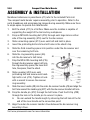
ASSEMBLY & INSTALLATION
Numbered references in parenthesis (#1) refer to the included Parts List.
The compact metal bender requires assembly prior to operation. Refer to the
parts breakdown and accompanying images during assembly. Make sure there
is ample space to operate the metal bender.
1. Bolt the stand (#11) to a flat floor. Make sure the location is capable of
supporting the weight of the tool and any workpieces.
2. Drop an M10x30 mounting bolt (#16) through each large hole on either
side of the ring assembly (#10) next to the die receiver.
3. Slide a mounting spacer (#13) over each bolt and hold in place.
4. Insert the protruding bolts into two bolt holes in the stand’s top.
5. Slide the third mounting spacer into position under the die receiver and
over the remaining bolt hole.
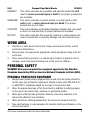
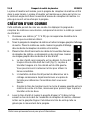
6. Slide the ring assembly spacer (#6)
into the die receiver’s bolt holes.
7. Drop the M10x120 mounting bolt (#15)
through the die receiver upper bolt hole,
the ring assembly spacer, the lower bolt
hole, the spacer, then the stand.
8. Slide a washer (#24) over each
protruding bolt and secure each hand-
tight with a nut (#14). Tighten all nuts
with a wrench to secure the receiver
ring assembly.
9. Slide the inner handle (#8) into the outer die receiver handle (#9) and align the
bolt hole nearest the handle grip (#27) with the die receiver handle bolt hole.
10. Drop the handle pin (#12) through the bolt holes. Push the R-Clip (#28)
through the hole in the handle pin to secure it in place.
A. You can extend the handle length by choosing the bolt hole at the far
end of the inner handle as the connection point.
11. Align the outer die receiver handle’s tines between the die receiver ring
assembly’s tines.
Fig. 1

8536625 Compact Floor Metal Bender V4.0
6 For technical questions call 1-800-665-8685
12. Drop the long hitch pin (#1) into the holes at the end of each set of tines so
both are connected at the center of the assembly ring.
OPERATION
WARNING! Keep fingers and hands away from moving parts at all times to
avoid a pinch or crushing injury.
The metal bender uses a combination of one or two dies and a stop block or
right angle die to create a curve or angle bend.
The workpiece is inserted, then the die receiver handle is pulled in a clockwise
direction. The workpiece is held in place by the block or right angle die in the die
receiver ring assembly. The part sticking out is bent by the handle.
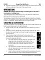
CREATING A CURVE BEND
This method creates a curve bend. Moving the die receiver handle clockwise will
bend the metal sticking out on the right-hand side.
1. Choose the die (#17 to 23) that matches the curve diameter you wish to
create.
2. Hold the die receiver handle and remove the center long hitch pin. Place
the die in the center. Drop the hitch pin through the die receiver
tines and the die.
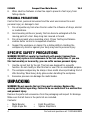
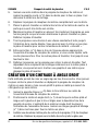
3. Place the square stop block between the die receiver ring
assembly tines, choosing one of the five holes. Drop a long pin
through the tines and stop block.
a. The square stop block has an offset hole. This hole must
always be on the right side of the tool (Fig. 2). The
workpiece will move if the offset hole is on the left side.
You may need to flip the block to obtain the correct
orientation.
b. The stop block’s orientation determines where the bend
will start. Experiment with scrap metal stock to learn what
orientation you will need.
c. Orient the block to provide the least amount of space between the center
die and the block, but enough to fit the workpiece between them.
Fig. 2

V4.0 Compact Floor Metal Bender 8536625
Visit www.princessauto.com for more information 7
4. Lift the stop block and drop the support pin (#5) into the next hole on the
bottom die receiver assembly tine. Lower the block onto the support pin.
This raises the block so it doesn’t interfere with the handle movement.
5. Insert another die into the die receiver handle and drop the short pin (#2)
through the tines to lock it into place. This will roll along the metal while
bending.
6. Move the die receiver handle all the way to the right.
7. Place the metal workpiece between the block and center die. The portion
that extends to the right will be bent.
8. Hold the workpiece and slowly pull the handle clockwise until tension holds
the workpiece in place. Release your grip on the workpiece.
9. Pull the handle clockwise at a slow and steady speed until you reach the
desired curve. You may need to bend the workpiece slightly more to
accommodate the metal’s tendency to ‘bounce back’.
10. Drop the stop (#4) into the appropriate outer ring hole in the die receiver
ring assembly, if you wish to repeat this curve bend multiple times. On
subsequent workpieces, pull until you hit the stop.
11. Release pressure on the handle to remove the workpiece. Depending on
the complexity of prior bends on the same workpiece, you may need to
remove a pin and die to free the workpiece.
CREATING AN ANGLE BEND
This method creates a sharp angle instead of a curve. You still bend the
workpiece by moving the die receiver handle clockwise, but the metal piece
sticking out on the left-hand side will be bent instead.
1. Insert the support pin (#5) in the bottom middle hole of the die receiver
ring assembly.
2. Position the right angle die (#7) so the long flat surface is on the left and
the hole aligns with the second hole from the center pin. The end of the
right angle die will touch the ring assembly spacer. Drop a long hitch pin
(#1) through the holes to lock the die in place.
3. Install a second die near the center of the die receiver handle (#9). Move
the handle out of the way to the right-hand side.

8536625 Compact Floor Metal Bender V4.0
8 For technical questions call 1-800-665-8685
4. Mark the workpiece where you wish to add an angle bend.
5. Insert metal workpiece between the right angle die and the center die. Align
the mark with the edge of the right angle die. The bending pressure will
apply to the workpiece sticking out on the left-hand side.
6. Hold the workpiece and slowly pull the handle clockwise until tension holds
the workpiece in place. Release your grip on the workpiece.
7. Pull the handle clockwise at a slow and steady speed until you reach the
desired angle. You may need to bend the workpiece slightly more to
accommodate the metal’s tendency to ‘bounce back’.
8. Drop the stop (#4) into the appropriate outer ring hole in the die receiver
ring assembly, if you wish to repeat this angle multiple times. On
subsequent workpieces, pull until you hit the stop.
9. Release pressure on the handle to remove the workpiece. Depending on
the complexity of prior bends on the same workpiece, you may need to
remove a pin and die to free the workpiece.
USING THE ADJUSTABLE STOP LOOP
The stop (#4) is suitable for general bends and angles. However, a precise angle
may fall between two holes on the die receiver ring assembly (#10). The
adjustable stop loop (#26) positions the stop between the ring holes.
1. Position the adjustable stop loop over the next ring hole beyond the
chosen stop position.
2. Drop an M10x30 mounting bolt (#25) through the rear stop loop hole and
the ring hole. Secure the mounting bolt hand-tight with a 10 mm washer
(#24) and an M10 nut (#14).
3. Drop the stop (#4) in the remaining stop loop hole. Push the stop loop into
position so the stop is in the correct place for the desired angle.
4. Tighten the bolt to secure the stop loop. Proceed with the bending tasks.
CARE & MAINTENANCE
1. Maintain the tool with care. A tool in good condition is efficient, easier to
control and will have fewer problems.

V4.0 Compact Floor Metal Bender 8536625
Visit www.princessauto.com for more information 9
2. Inspect the tool components periodically. Repair or replace damaged or
worn components. Only use identical replacement parts when servicing.
3. Follow instructions for lubricating and changing accessories.
4. Only use accessories intended for use with this tool.
5. Keep the tool handles clean, dry and free from oil/grease at all times.
6. Maintain the tool’s labels and name plates. These carry important information.
If unreadable or missing, contact Princess Auto Ltd. for replacements.
WARNING! Only qualified service personnel should repair the tool. An
improperly repaired tool may present a hazard to the user and/or others.
LUBRICATION
Inspect and lubricate the tool when required. Only use light oil to lubricate the
tool. Other lubricants may not be suitable and could damage the tool or cause a
malfunction during use.
STORAGE
When not in use for an extended period, apply a thin coat of lubricant to the
steel parts to avoid rust. Remove the lubricant before using the tool again.
DISPOSAL
Recycle a tool damaged beyond repair at the appropriate facility.
TROUBLESHOOTING
Visit a Princess Auto Ltd. location for a solution if the tool does not function
properly or parts are missing. If unable to do so, have a qualified technician
service the tool.

8536625 Compact Floor Metal Bender V4.0
10 For technical questions call 1-800-665-8685
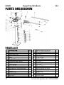
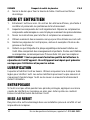
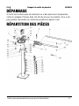
PARTS BREAKDOWN
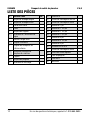
PARTS LIST
#
DESCRIPTION
QTY
1
Long Hitch Pin
2
2
Short Hitch Pin
1
3
Square Stop Block
1
4
Stop
1
5
Support Pin
1
6
Ring Assembly Spacer
1
7
Right Angle Die
1
8
Inner Handle
1
9
Outer Die Receiver Handle
1
10
Die Receiver Ring Assembly
1
11
Stand
1
12
Handle Pin
1
13
Mounting Spacer
3
14
Nut M10
4
15
Mounting Bolt M10x120
1
16
Mounting Bolt M10x30
2
17
1 in. Die
1
18
1-1/4 in. Die
1
19
1-1/2 in. Die
2
20
1-3/4 in. Die
1
21
2 in. Die
1
22
2-1/2 in. Die
1
23
3 in, Die
1
24
Washer 10 mm
4
25
Mounting Bolt M10x30
1
26
Adjustable Stop Loop
1
27
Handle Grip
1
28
R-Clip
1
29
Screw Driver
1

V4.0 Compact Floor Metal Bender 8536625
Visit www.princessauto.com for more information 11

8536625 Compact Floor Metal Bender V4.0
12 For technical questions call 1-800-665-8685

V 4,0 8536625
Vous devez lire et comprendre toutes les instructions avant d'utiliser l'appareil.
Conservez ce manuel afin de pouvoir le consulter plus tard.
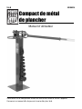
Manuel d'utilisateur
Compact de métal
de plancher

8536625 Compact de métal de plancher V 4,0
2 En cas de questions techniques, appelez le 1-800-665-8685
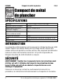
SPÉCIFICATIONS
Matrices 1, 1 1/4, 1 1/2(2), 1 3/4, 2, 2 1/2, 3 po
Épaisseur max. de la matière 5/16 po
Capacité pour l'acier doux
(épaisseur x largeur)
5/16 x 1 1/4 ou 1/4 x 2
Capacité en matière de tiges
pleines rondes ou carrées
5/8 po
Longueur de la poignée 44 po
Base 10 po carrés avec 4 orifices de montage de 1/2 po
Hauteur totale 44 po
INTRODUCTION
La compact de métal de plancher est conçue pour le cintrage de pièces en métal
solides. Réglée à une hauteur idéale pour le cintrage manuel, elle peut être
utilisée comme outil portatif ou comme outil fixe. Elle comprend huit différentes
matrices à cintrer dont les tailles varient de 1 à 3 po afin de permettre de
fabriquer des pièces de métal standards ou uniques.
SÉCURITÉ
AVERTISSEMENT ! Veuillez lire et comprendre toutes les instructions avant
d'utiliser cet outil. L'utilisateur doit respecter les précautions de base
lorsqu'il utilise cet outil afin de réduire le risque de blessure ou de
dommage à l'équipement.
Conservez ce manuel qui contient les avertissements de sécurité, les
précautions, les instructions de fonctionnement ou d'inspection et d'entretien.
Compact de métal
de plancher

V 4,0 Compact de métal de plancher 8536625
Visitez www.princessauto.com pour plus d'informations 3
DÉFINITIONS DE DANGER
Veuillez-vous familiariser avec les avis de danger qui sont présentés dans ce
manuel. Un avis est une alerte indiquant qu'il existe un risque de dommage à la
propriété, de blessure ou de décès si on ne respecte pas certaines instructions.
DANGER ! Cet avis indique un risque immédiat et particulier qui
entraînera des blessures corporelles graves ou même la
mort si on omet de prendre les précautions nécessaires.
AVERTISSEMENT ! Cet avis indique un risque particulier ou une pratique non
sécuritaire qui pourrait entraîner des blessures
corporelles graves ou même la mort si on omet de
prendre les précautions nécessaires.
ATTENTION ! Cet avis indique une situation possiblement dangereuse qui
peut entraîner des blessures mineures ou modérées si on
ne procède pas de la façon recommandée.
AVIS ! Cet avis indique un risque particulier ou une pratique non
sécuritaire qui entraînera des dommages au niveau de
l'équipement ou des biens, mais non des blessures corporelles.
AIRE DE TRAVAIL
1. Travaillez dans un environnement de travail sécuritaire. Gardez votre aire
de travail propre, bien éclairée et exempte de toute distraction.
2. Assurez-vous que les personnes qui ne portent pas l'équipement de
sécurité approprié ne se trouvent pas à proximité de l'aire de travail.
3. Rangez les outils correctement dans un lieu sécurisé et sec. Gardez les
outils hors de la portée des enfants.
SÉCURITÉ PERSONNELLE
AVERTISSEMENT ! Portez de l'équipement de protection personnelle
homologué par l'Association canadienne de normalisation (CSA) ou
l'American National Standards Institute (ANSI).
ÉQUIPEMENT DE PROTECTION PERSONNELLE
1. Portez toujours des lunettes antiprojections qui offrent une protection
frontale et latérale pour les yeux. L'équipement de protection des yeux

8536625 Compact de métal de plancher V 4,0
4 En cas de questions techniques, appelez le 1-800-665-8685
devrait être conforme à la norme CSA Z94.3-07 ou ANSI Z87.1 fonction du
type de travail effectué.
2. Portez un écran facial panoramique de type approprié avec les lunettes de
sécurité puisque cette tâche peut créer des copeaux, des matières
abrasives ou des particules.
3. Portez des gants qui protègent en fonction des matériaux de travail et pour
réduire les effets des vibrations de l'outil.
4. Portez des vêtements de protection conçus pour l'environnement de travail
et pour l'outil.
5. Les chaussures antidérapantes sont recommandées pour maintenir la
stabilité et l'équilibre au sein de l'environnement de travail.
6. Portez des chaussures à embout d'acier ou à coquilles d'acier pour éviter
les blessures aux pieds dues à la chute d'objets.
PRÉCAUTIONS PERSONNELLES
Gardez le contrôle de l'outil, de vos mouvements et de l'environnement de
travail pour éviter les blessures ou le bris de l'outil.
1. N'utilisez pas l'outil si vous êtes fatigué ou sous l'effet de drogues, d'alcool
ou de médicaments.
2. Évitez de porter des vêtements ou des bijoux pouvant se prendre dans les
pièces mobiles d'un outil. Gardez les cheveux longs recouverts ou attachés.
3. N'utilisez pas l'outil si vous devez étirer les bras pour vous en servir. Une
stabilité et un équilibre appropriés sont nécessaires afin d'avoir un meilleur
contrôle en cas de situations inattendues.
4. Soutenez la pièce à travailler ou fixez-la sur une plate-forme stable. Une
pièce à travailler tenue dans les mains ou appuyée contre votre corps sera
instable et peut entraîner des blessures corporelles.
CONSIGNES DE SÉCURITÉ SPÉCIFIQUES
AVERTISSEMENT! Ne permettez PAS au confort ou à votre familiarisation
avec l'outil (obtenus après un emploi répété) de se substituer à une
adhésion stricte aux règles de sécurité de l'outil. Si vous utilisez cet outil
de façon dangereuse ou incorrecte, vous pouvez subir des blessures
corporelles graves.

V 4,0 Compact de métal de plancher 8536625
Visitez www.princessauto.com pour plus d'informations 5
1. Utilisez le bon outil pour la tâche à effectuer. Cet outil a été conçu pour une
utilisation spécifique. Évitez de modifier ou d'altérer cet outil ou de l'utiliser à
une fin autre que celle pour laquelle il a été conçu.
2. Les rebords de la pièce à travailler peuvent présenter des arêtes vives ou
des limailles de métal en saillie suite au cintrage. Portez des gants épais
lorsque vous manipulez la pièce à travailler.
3. Une pression excessive peut endommager la cintreuse de métal.
DÉBALLAGE
AVERTISSEMENT ! Ne faites pas fonctionner l'outil si des pièces sont
manquantes. Remplacez les pièces manquantes avant l'utilisation. Le
non-respect de cet avertissement peut entraîner une défectuosité et des
blessures graves.
Retirez les pièces et les accessoires de l'emballage et vérifiez s'il y a des
dommages. Assurez-vous que tous les articles sur la liste de pièces sont compris.
Contenu : • Cintreuse de metal • 8 matrices rondes
• Matrice à angle droit • Bloc d’arrêt carré
ASSEMBLAGE ET INSTALLATION
Les numéros de référence entre parenthèses (n
o
1) se rapportent à la liste de
pièces comprise.
La cintreuse de métal compacte doit être assemblée avant d’être utilisée.
Consultez la répartition des pièces et les images jointes pendant l’assemblage.
Assurez-vous qu’il y a assez d’espace pour utiliser la cintreuse de métal.
1. Boulonnez le socle (n
o
11) à un plancher de niveau. Assurez-vous que
l’outil est placé sur une surface pouvant supporter le poids de l’outil et des
pièces à travailler.
2. Insérez un boulon de montage M10 x 30 (n
o
16) dans chaque grand trou des
deux côtés de l’ensemble d’anneau (n
o
10) à côté du récepteur de matrice.
3. Glissez une entretoise de montage (n
o
13) sur chaque boulon et maintenez-
les en place.
4. Insérez les boulons saillants dans deux trous de boulon dans le haut du socle.

8536625 Compact de métal de plancher V 4,0
6 En cas de questions techniques, appelez le 1-800-665-8685
5. Glissez la troisième entretoise de montage en place sous le récepteur de
matrice et sur le dernier trou de boulon.
6. Glissez l’entretoise (n
o
6) de l’ensemble d’anneau dans les trous de boulon
du récepteur de matrice.
7. Insérez le boulon de montage M10 x 120 (n
o
15) dans le trou de boulon
supérieur du récepteur de matrice, l’entretoise de l’ensemble d’anneau, le trou
de boulon inférieur, l’entretoise et le socle.
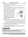
8. Glissez une rondelle (n
o
24) sur chaque
boulon saillant et serrez-les à la main
avec un écrou (n
o
14). Serrez tous les
écrous au moyen d’une clé afin de fixer
l’ensemble d’anneau du récepteur.
9. Glissez la poignée interne (no 8) dans la
poignée externe (n
o
9) du récepteur de
matrice et alignez le trou de boulon le
plus près de la prise de poignée (n
o
27)
au trou de boulon de la poignée du
récepteur de matrice.
10. Insérez la goupille (n
o
12) de la poignée dans les trous de boulon. Enfoncez la
pince en R (n
o
28) dans le trou de goupille de la poignée pour la fixer en place.
a. Vous pouvez augmenter la longueur de la poignée en choisissant le trou
de boulon à l’autre bout de la poignée interne comme point de connexion.
11. Alignez les dents de la poignée du récepteur de matrice entre les dents de
l’ensemble d’anneau du récepteur de matrice.
12. Insérez la longue goupille d’attelage (n
o
1) dans les trous à l’extrémité de
chaque jeu de dents afin que les deux soient connectés au centre de
l’ensemble d’anneau.
UTILISATION
AVERTISSEMENT ! En tout temps, tenez les doigts et les mains à l’écart des
pièces mobiles afin d’éviter de les coincer ou de les écraser.
La cintreuse de métal utilise une combinaison d’une ou de deux matrices et d’un
bloc d’arrêt ou d’une matrice à angle droit pour créer une courbe ou un coude.
Fig. 1

V 4,0 Compact de métal de plancher 8536625
Visitez www.princessauto.com pour plus d'informations 7
La pièce à travailler est insérée, puis la poignée du récepteur de matrice est tiré
dans le sens horaire. La pièce à travailler est maintenue en place par le bloc ou
la matrice à angle droit dans l’ensemble d’anneau du récepteur de matrice. La
pièce qui ressort est courbée par la poignée.
CRÉATION D’UNE COURBE
Cette méthode permet de créer une courbe. En déplaçant la poignée du
récepteur de matrice en sens horaire, cela permet de cintrer le métal qui ressort
du côté droit.
1. Choisissez une matrice (n
os
17 à 23) qui correspond au diamètre de la
courbe que vous désirez obtenir.
2. Tenez la poignée du récepteur de matrice et retirez la longue goupille d’attelage
du centre. Placez la matrice au centre. Insérez la goupille d’attelage
dans les dents du récepteur de matrice et la matrice.
3. Placez le bloc d’arrêt carré entre les dents de l’ensemble d’anneau
du récepteur de matrice, en choisissant un des cinq trous. Insérez
une longue goupille dans les dents et le bloc d’arrêt.
a. Le bloc d’arrêt carré comporte un trou décalé. Ce trou doit
toujours être du côté droit de l’outil (fig. 2). La pièce à
travailler bougera si le trou décalé est du côté gauche.
Vous pourriez avoir à retourner le bloc pour obtenir la
bonne orientation.
b. L’orientation du bloc d’arrêt permet de déterminer où le
cintrage commencera. Expérimentez avec une pièce de
ferraille pour déterminer l’orientation dont vous aurez
besoin.
c. Orientez le bloc de manière à avoir le moins d’espace possible entre la
matrice du centre et le bloc, mais assez pour pouvoir loger la pièce à
travailler entre les deux.
4. Levez le bloc d’arrêt et insérez la goupille d’appui (n
o
5) dans le trou
suivant au bas de la dent de l’ensemble de récepteur de matrice. Abaissez
le bloc sur la goupille d’appui. Cela élèvera le bloc de sorte qu’elle ne
gênera pas le mouvement de la poignée.
Fig. 2

8536625 Compact de métal de plancher V 4,0
8 En cas de questions techniques, appelez le 1-800-665-8685
5. Insérez une autre matrice dans la poignée du récepteur de matrice et
insérez la goupille courte (n
o
2) dans les dents pour la fixer en place. Ceci
déroulera le métal lors du cintrage.
6. Déplacez la poignée du récepteur de matrice complètement vers la droite.
7. Placez la pièce à travailler en métal entre le bloc et la matrice du centre. La
partie qui ressort à la droite sera cintrée.
8. Maintenez la pièce à travailler en place et tirez lentement la poignée en sens
horaire jusqu’à ce que la tension maintienne la pièce à travailler en place.
Relâchez la pièce à travailler.
9. Tirez la poignée en sens horaire à une vitesse constante et lente jusqu’à
l’obtention de la courbe désirée. Vous pourriez avoir à cintrer un peu plus
la pièce à travailler pour contrer la tendance du métal à « rebondir ».
10. Enfoncez le bloc (n
o
4) dans le trou de l’anneau externe approprié de
l’ensemble d’anneau du récepteur de matrice, si vous voulez répéter cette
courbe plusieurs fois. Pour les autres pièces à travailler, tirez jusqu’à vous
touchiez le bloc.
11. Relâchez la pression sur la poignée pour retirer la pièce à travailler. Tout
dépendant de la complexité des cintrages antérieurs sur la même pièce à
travailler, vous pourriez avoir à retirer une goupille et une matrice pour
dégager la pièce à travailler.
CRÉATION D’UN CINTRAGE À ANGLE DROIT
Cette méthode permet de créer un angle aigu au lieu d’une courbe. Vous pouvez
toujours cintrer la pièce à travailler en déplaçant la poignée du récepteur de
matrice en sens horaire, mais ce sera plutôt la pièce en métal qui ressort du
côté gauche qui sera cintrée.
1. Insérez la goupille d’appui (n
o
5) dans le trou inférieur au centre de
l’ensemble d’anneau du récepteur de matrice.
2. Positionnez la matrice à angle droit (n
o
7) de sorte que la surface plate et
longue est à gauche et que le trou s’aligne avec le deuxième trou de la
goupille du centre. L’extrémité de la matrice à angle droit touchera à
l’entretoise de l’ensemble d’anneau. Insérez une longue goupille d’attelage
(n
o
1) dans les trous pour fixer la matrice en place.
3. Installez une deuxième matrice près du centre de la poignée (n
o
9) du récepteur
de matrice. Déplacez la poignée vers la droite de sorte qu’elle ne gêne pas.
La page est en cours de chargement...
La page est en cours de chargement...
La page est en cours de chargement...
La page est en cours de chargement...
-
 1
1
-
 2
2
-
 3
3
-
 4
4
-
 5
5
-
 6
6
-
 7
7
-
 8
8
-
 9
9
-
 10
10
-
 11
11
-
 12
12
-
 13
13
-
 14
14
-
 15
15
-
 16
16
-
 17
17
-
 18
18
-
 19
19
-
 20
20
-
 21
21
-
 22
22
-
 23
23
-
 24
24


dans d''autres langues
- English: Power Fist 8536625 User manual
Documents connexes
-
Power Fist 8169781 Parts list
-
-
-
-
-
-
-
-
-