
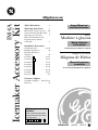
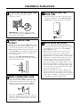
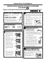
Icemaker Accessory Kit
GEAppliances.com
IM-4A
162D4614P012 49-60283 08-03 JR
Safety Information . . . . . . . . . 2
Operating Instructions . . . . . .3
Before You Call For Service . .4–6
Normal Sounds You May Hear . .3
Preparing for Vacation . . . . . . .3
When You Should Set the
Icemaker Power Switch
to O (Off) . . . . . . . . . . . . . . . . .3
Installation Instructions
Cold Water Line . . . . . . . . .38–41
Fill Tube Templates . . . . . . . . .42
Fill Tube Extension
Templates . . . . . . . . . . . . . . . .42
Icemaker . . . . . . . . . . .10–13
Icemaker . . . . . . . . . . .14–17
Icemaker . . . . . . . . . . .18–21
Icemaker . . . . . . . . . . .22–25
Icemaker . . . . . . . . . . .26–29
Icemaker . . . . . . . . . . .30–33
Icemaker . . . . . . . . . . .34–37
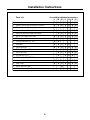
Parts List . . . . . . . . . . . . . . . .8, 9
Consumer Support
Consumer Support . . Back Cover
Warranty . . . . . . . . . . . . . . . . . 43
S
R
Q
P
N
M
L
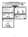
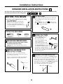
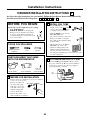
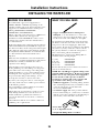
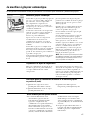
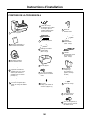
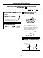
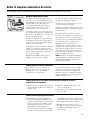
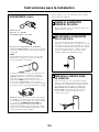
Which instructions should
you follow?
Look for a label on the back of the
refrigerator that will tell you which
instructions to use:
or
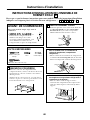
SRQPNML
Machine à glaçons
Trousse
Máquina de Hielos
Equipo de Accesorios
Manuel d’utilisation
et d’installation
Owner’s Manual and
Installation Instructions
Manual del propietario
e instalación
La section française commence à la page 44
La sección en español empieza en la página 92
★

2
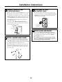
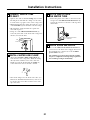
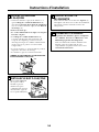
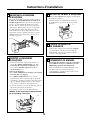
READ AND FOLLOW THIS SAFETY INFORMATION CAREFULLY.
READ AND SAVE THESE INSTRUCTIONS
SAFETY PRECAUTIONS
IMPORTANT SAFETY INFORMATION.
READ ALL INSTRUCTIONS BEFORE USING.
FOR YOUR SAFETY:
Do not place fingers or hands in the automatic
icemaking mechanism while the refrigerator is
plugged in. This will help protect you from
possible injury.
It will also prevent interference with moving
parts of the ejector mechanism and the heating
element that releases the cubes, located on the
bottom of the icemaker.

3
■ The icemaker water valve will buzz when
the icemaker fills with water. If the power
switch is in the I (on) position, it will buzz
even if it has not yet been hooked up to
water. Keeping the power switch in the
I (on) position before it is hooked up to
water can damage the icemaker. To
prevent this, move the power switch to
the O (off) position. This will stop
the buzzing.
■ The sound of cubes dropping into the bin
and water running in the pipes as the
icemaker refills.
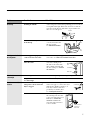
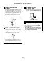
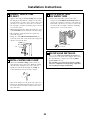
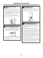
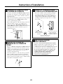
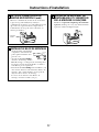
About the automatic icemaker. GEAppliances.com
A newly-installed refrigerator may take 12 to 24 hours to begin making ice.
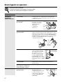
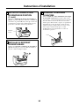
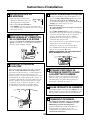
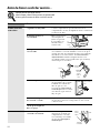
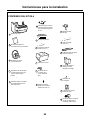
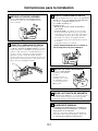
Icemaker
Feeler Arm
Power
Switch
Automatic Icemaker
The icemaker will produce seven cubes
per cycle---approximately 100–130 cubes
in a 24-hour period, depending on
freezer compartment temperature, room
temperature, number of door openings
and other use conditions.
If the refrigerator is operated before the
water connection is made to the icemaker,
set the power switch to O (off).
When the refrigerator has been connected
to the water supply, set the power switch to
I (on). The green light will come on.
The icemaker will fill with water when
it cools to freezing. A newly-installed
refrigerator may take 12 to 24 hours
to begin making ice cubes.
You will hear a buzzing sound each time
the icemaker fills with water.
Throw away the first few batches of ice to
allow the water line to clear.
Be sure nothing interferes with the sweep
of the feeler arm.
When the bin fills to the level of the feeler
arm, the icemaker will stop producing ice.
It is normal for several cubes to be joined
together.
If ice is not used frequently, old ice cubes
will become cloudy, taste stale and shrink.
If ice cubes get stuck in the icemaker, the
green power light will blink. To correct
this, set the power switch to O (off) and
remove the cubes. Set the power switch to
I (on) to restart the icemaker.
NOTE: In homes with lower-than-average water
pressure, you may hear the icemaker cycle multiple
times when making one batch of ice.
Green Power Light
Preparing for Vacation
Set the icemaker power switch to O (off)
and shut off the water supply to the
refrigerator.
If the temperature can drop below freezing,
have a qualified servicer drain the water
supply system (on some models) to prevent
serious property damage due to flooding.
When you should set the icemaker power switch to O (off)
■ When the ice storage bin is removed for
more than a minute or two.
■ When the water supply will be shut off for
several hours.
■ When the refrigerator will not be used for
several days.
Normal sounds you may hear

4
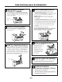
Problem Possible Causes What To Do
Automatic icemaker Freezer compartment • After installing the kit, allow the refrigerator to completely
does not work/’not too warm. cool down for 24 hours. Once the compartment is cool, the
icemaker will begin ice production.
Icemaker is not turned on. • Move the icemaker
power switch to the
I (on) position.
The indicator light
below the switch
will turn green.
Icemaker is not plugged • If using a power cord adapter, make sure that it is fully
in correctly. connected. Also check that the icemaker cord plug is fully
inserted into the socket. See Plug in the icemaker. When the
icemaker is turned on, the green power indicator light
below the switch will turn on.
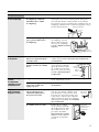
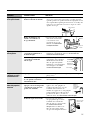
Water line kinked. • Check that the plastic water
line running from the valve
to the water tube inlet is not
kinked. See Connect the
water line. A kink in the
water line will restrict flow
to the water line.
Water supply turned off or • After installing the kit, make sure the house water supply
not connected. to the refrigerator has been turned on.
Piled up cubes in the storage bin • Level cubes by hand.
cause the icemaker to shut off.
Water valve is not plugged in • Check that the valve wire
correctly. adapter is completely
plugged onto the male
connector plug and the
terminals on the water valve.
See Attach the water valve.
Before you call for service…
Troubleshooting Tips
Save time and money! Review the following chart first
and you may not need to call for service.
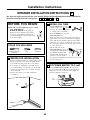
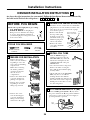
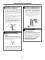
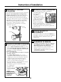
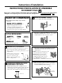
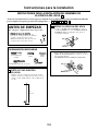
Power
Switch
Green
Indicator
Light
Feeler Arm
Icemaker
Clip
Restraints
onto
Locking
Tabs
Locking
Tabs
Hook
Adhesive-backed
Fasteners for
Water Tube
Male
Connector
Plug
Valve
Terminals

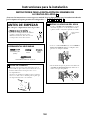
Problem Possible Causes What To Do
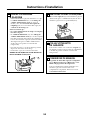
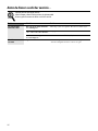
Leaking water around Foam in the fill cup from • If the fill tube was installed by sliding it through the back
the fill cup installing the fill tube. of the refrigerator, it may have picked up pieces of foam as
it was pushed through. This foam can interfere with the
water flow in the fill cup. Check the cup and make sure
there are no foam pieces.
Fill tube not correctly seated • Check that the fill tube is
in the fill cup. correctly inserted in the
fill cup opening.
See Mount the icemaker.
Leaking water behind House supply not properly • Check that the house supply is firmly attached to the
the refrigerator connected to the water valve. water valve. See Water line installation instructions.
Water line not connected to the • Check that the plastic
water tube inlet. water line running from
the valve to the water tube
inlet is firmly attached with
the hose clamp. See Connect
the water line.
Slow ice/freezer not Door left open. • Check to see if package is holding door open.
cold enough
Temperature control not •See About the Temperature Control.
set cold enough.
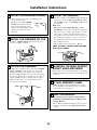
Ice cubes too small/ Water shutoff valve connecting •We recommend drilling a 1/4″ hole
slow ice refrigerator to house water line in the water pipe to connect the water
may be clogged. shut-off valve. Failure to drill a 1/4″
hole may result in reduced ice
production or smaller cubes.
See Installing the water line.
Water line kinked. •Check that the plastic water
line running from the valve
to the water tube inlet is not
kinked. See Connect the
water line. A kink in the
water line will restrict flow
to the icemaker.
5
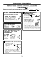
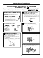
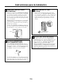
Fill Tube
Fill
Tube
Fill
Cup
Water Tube
Inlet
Hose Clamp
Water Line
Adhesive-backed
Fasteners for
Water Tube
Drill 1/4″ hole
in water pipe

Problem Possible Causes What To Do
Ice cubes have Ice storage bin needs cleaning. •Empty and wash bin. Discard old cubes.
odor/taste
Food transmitting odor/taste •Wrap foods well.
to ice cubes.
Interior of refrigerator •See Care and cleaning.
needs cleaning.
Frequent “buzzing” Normal operation. •During normal operation, the water valve will “buzz”
sound when the icemaker fills with water.
Before you call for service…
Troubleshooting Tips
Save time and money! Review the following chart first
and you may not need to call for service.
6

7
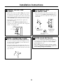
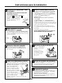
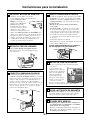
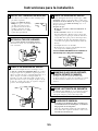
BEFORE YOU BEGIN
Installation IM-4A
Instructions Icemaker Kit
Read these instructions completely and carefully.
•
IMPORTANT – Save these
instructions for local inspector’s use.
•
IMPORTANT – Observe all
governing codes and ordinances.
• Note to Installer – Be sure to leave these
instructions with the Consumer.
• Note to Consumer – Keep these instructions
for future reference.
• Skill level – Installation of this appliance requires
basic mechanical and electrical skills.
• Completion time – 20–60 minutes
• Proper installation is the responsibility of the
installer.
• Product failure due to improper installation is
not covered under the Warranty.
It’s important that you use the water valve and fill tube
extension that come with this kit, even though your
refrigerator may already have them installed.
The old valve will not allow enough water through
to fill the icemaker properly and will cause damage.
The fill tube extension needs to be a different length
than the original tube for proper water flow. Cut the
tube to the length indicated for your model of
refrigerator.
ARE YOU REPLACING AN
ICEMAKER WITH THIS KIT?
Questions? Call 800.GE.CARES (800.432.2737) or Visit our Website at: GEAppliances.com
In Canada, call 1.800.361.3400
or Visit our Website at: geappliances.ca
There is a label on the back of the refrigerator
that will tell you whether to use Instructions:
or
Pages 10–37 contain seven different Installation
Instructions.
The actual installation of the icemaker will depend
on which model refrigerator you have.
SRQPNML
WHICH INSTRUCTIONS SHOULD
YOU FOLLOW?
• If the unit is damaged in shipment, return the unit
to the store in which it was bought for repair or
replacement.
• If the unit is damaged by the customer, repair or
replacement is the responsibility of the customer.
• If the unit is damaged by the installer (if other than
the customer), repair or replacement must be made
by arrangement between customer and installer.
DAMAGE – SHIPMENT/INSTALLATION

8
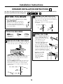
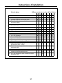
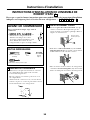
Installation Instructions
CONTENTS OF KIT IM-4A
Owner’s Manual &
Installation Instructions
2
Ice Bucket
9
Water Line Clamp
(strain relief), for
house water line
6
Hex-Head Screw
for Water Line Clamp
5
Water Valve and
Tube Assembly
3
Hex-Head Screw, for
attaching water valve
10
Adhesive-Backed Water Tube
Fasteners, to secure plastic
water tube (4)
4
12
Water Tube Inlet
11
Phillips Head Screws,
for mounting icemaker (2)
Warranty Label
7
ICEMAKER
WARRANTY VERIFICATION
Date Installed
Dealer
Fill Tube Extension
(3/4″ O.D.)
8
15
Fill Tube
(5/8″ O.D.)
13
Fill Tube with Foil
(5/8″ O.D.)
14
Icemaker Fill Cup
(side-mounted)
Icemaker
1
I
n
s
t
a
l
l
a
t
i
o
n
I
n
s
t
r
u
c
t
i
o
n
s
16
Hose Clamp
Water Tube
Inlet Cover
17
Hex-Head Screws, for
attaching water tube
inlet cover
18

9
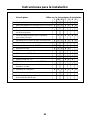
Installation Instructions
Parts List Use with Installation Instructions:
LMNPQRS
1 Icemaker XXXXXXX
2 Owner’s Manual and Installation Instructions XXXXXXX
3 Water Valve and Tube Assembly XXXXXXX
4 Adhesive-Backed Water Tube Fasteners XXXXXXX
5 Hex-Head Screw for Water Line Clamp XXXXXX
6 Water Line Clamp (strain relief) XXXXXXX
7 Warranty Label XXXXXXX
8 Fill Tube Extension (3/4″ O.D.) XX
9 Ice Bucket XXXXX
10 Hex-Head Screw XXXXXXX
11 Phillips Head Screw (2) XX XX
12 Water Tube Inlet XXXXXX
13 Fill Tube (5/8″ O.D.) X XXX
14 Fill Tube with Foil (5/8″ O.D.) X
15 Icemaker Fill Cup (side-mounted) XXXXXXX
16 Hose Clamp XXXXXXX
17 Water Tube Inlet Cover X
18 Hex Head Screw (2) for Water Tube Inlet Cover X

10
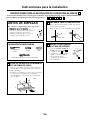
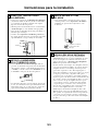
2
Installation Instructions
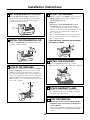
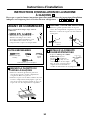
ICEMAKER INSTALLATION INSTRUCTIONS L
Are these the right instructions for your model? Follow the Installation Instructions indicated by
the label on the back of the refrigerator--- or
SRQPNML
BEFORE YOU BEGIN
Read each step thoroughly before proceeding.
•
CAUTION – Unplug the
Refrigerator. To eliminate the danger
of electric shock during installation,
you must unplug the refrigerator
from its electrical outlet.
Flat blade and Phillips
screwdrivers
Pliers
TOOLS YOU WILL NEED
Sharp knife
1
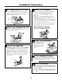
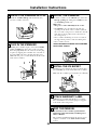
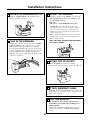
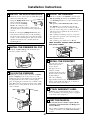
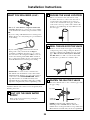
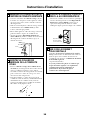
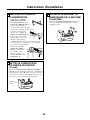
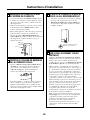
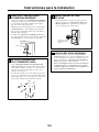
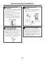
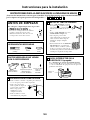
REMOVE ICE CUBE TRAY SHELF
• Remove the two screws securing the ice cube tray
to the side wall of the freezer. Remove the tray.
• Replace the screws but do not screw them all the
way in. The screw heads should extend about
1/2″ (13 mm) from the side wall of the freezer.
1/4″ Nutdriver or adjustable wrench
Remove
plug
INSTALL FILL TUBE EXTENSION
• Cut the fill tube extension (8)
to the length (refer to the
template on page 42) with
a sharp knife or a single-edge
razor blade and slide it onto
the fill tube against the stop.
L
L
3
PREPARE FOR INSTALLATION
• Remove and discard the large white plug from
the rear freezer wall.
• Remove the outlet cover with a flat-blade
screwdriver.
L
8

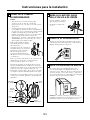
INSTALL THE ICE BUCKET
Put the ice bucket (9) in
place under the icemaker.
Make sure the icemaker
power switch is set to
O (off).
Installation Instructions
INSTALL THE ICEMAKER FILL CUP
Install the icemaker fill cup (side-mounted) (15)
into the icemaker as shown.
5
PLUG IN THE ICEMAKER
Holding the icemaker in place, insert the icemaker
power cord plug into the socket, making sure that
the prongs and holes are matched. Press the plug
firmly into the socket. Lock the plug in place by
clipping the restraints onto each side of the plug.
Make sure the restraints click into place. Make sure
the power cord is still in the hook on the back of
the icemaker.
6
ATTACH WARRANTY LABEL
A label (7) is provided with this kit to record the
date of installation for warranty purposes. Apply it
to the back of the refrigerator.
9
KEEP THIS MANUAL
The warranty for the icemaker is printed in this
manual. Keep this manual with your Refrigerator
Owner’s Manual.
The icemaker installation inside the freezer is now
complete. Continue to the Water Valve Assembly
section.
10
15
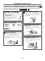
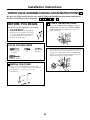
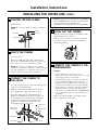
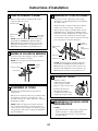
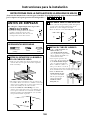
MOUNT THE ICEMAKER
• Lift the icemaker so the fill tube extension (8)
fits in the fill cup opening (C). Hang the
icemaker on the two mounting screws (A).
Make sure:
• The power cord is still firmly in the socket.
• The fill tube extension (8) is still in the fill cup
opening. (Check the rear of the refrigerator to
make sure the fill tube has not been pushed out
of the back of the refrigerator.)
• The icemaker mounting screws are located in
the uppermost position of the mounting slots.
• The icemaker is level.
THEN TIGHTEN THE ICEMAKER
MOUNTING SCREWS SECURELY.
7
8
C
A
8
11
SET POWER SWITCH TO O (off)
Set the icemaker power switch to O (off). Leave
the power switch in the O (off) position until the
refrigerator is connected to the water supply to
prevent premature operation.
4
Power
Switch
9
Hook

12
Installation Instructions
REMOVE THE COVER
At the bottom rear of the refrigerator, remove the
screw(s) holding the access cover.
Bend the cover back for access to the compartment.
Be sure to save the screws as the access cover must
be reinstalled later to ensure your refrigerator will
function properly.
1
BEFORE YOU BEGIN
Read each step thoroughly before proceeding.
•
CAUTION – Unplug the
Refrigerator. To eliminate the danger
of electric shock during installation,
you must unplug the refrigerator from
its electrical outlet.
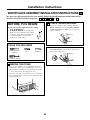
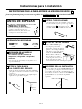
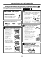
WATER VALVE ASSEMBLY INSTALLATION INSTRUCTIONS L
Are these the right instructions for your model? Follow the Installation Instructions indicated by
the label on the back of the refrigerator--- or
SRQPNML
Flat blade and Phillips
screwdrivers
Pliers
TOOLS YOU WILL NEED
Sharp knife
1/4″ and 5/16″ Nutdrivers
• Fasten the water valve to the
cabinet by driving
the
hex-head screw (10) from the kit into the
hole in the cabinet leg.
ATTACH THE WATER VALVE
• Locate the female connector plug (C), which is
attached to the cabinet by a metal or plastic clip.
Remove the clip by removing the screw.
2
• Plug the female connector (C) onto the male
terminals on the water valve (3). Either wire
can go on either terminal.
Metal or plastic clip
C
C
3
10

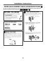
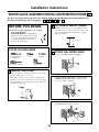
Installation Instructions
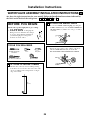
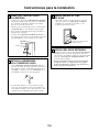
ROUTE AND ATTACH
THE WATER TUBE
• Fasten the plastic water tube to the back of the
refrigerator with the remaining adhesive-backed
fasteners (4), spacing the fasteners as shown to
take up slack in the tube.
5
WATER VALVE INSTALLED
Refer to the Water Line Installation Instructions for
connection to the home water supply. After water
line installation is completed, set the icemaker
power switch to I (on).
The icemaking cycle will not begin until the icemaker
and freezer compartment reach operating temperature,
then icemaking will begin automatically.
6
Adhesive-backed
fasteners for
water tube
13
INSTALL WATER LINE CLAMP
• Attach the metal water line clamp (strain relief)
(6) to the refrigerator. Drive one of the screws,
removed in Step 1, into the cabinet edge through
the clamp and hole in compressor cover.
• The metal clamp is for the house water line (see
Water Line Installation Instructions). It is not to
be used for the water tube from the water valve
up to the inlet.
4
6
Screw
CONNECT WATER TUBE
TO EXISTING INLET
• Squeeze the ends of the hose clamp (16) from the
kit with pliers and slide the clamp over the inlet,
located in the top right corner of the refrigerator.
• While still squeezing the clamp, insert the free end
of the water tube (3) into the inlet as far as it will go.
• Then slide the clamp downward to capture the
water tube in place.
• Using one of the adhesive-backed fasteners (4),
secure the water tube to the back of the refrigerator
about 1/2″ below the inlet.
3
16
4
Inlet
3

14
CUT FILL TUBE
• If the refrigerator already has a water tube and
inlet assembly on the back of the refrigerator,
go to Step 5.
• Cut the fill tube (13) to the length (refer to
the templates on page 42) with a sharp knife
or a single-edge razor blade.
M
M
3
Installation Instructions
ICEMAKER INSTALLATION INSTRUCTIONS M
Are these the right instructions for your model? Follow the Installation Instructions indicated by
the label on the back of the refrigerator--- or
SRQPNML
BEFORE YOU BEGIN
Read each step thoroughly before proceeding.
•
CAUTION – Unplug the
Refrigerator. To eliminate the danger
of electric shock during installation,
you must unplug the refrigerator from
its electrical outlet.
Flat blade and Phillips
screwdrivers
Pliers
TOOLS YOU WILL NEED
Sharp knife
REMOVE THE WHITE PLUG
AND OUTLET COVER
• Remove the outlet cover with a flat-blade
screwdriver located either on the left or back
freezer wall near the top.
• Remove and discard the white plug from the
upper left hand corner of the freezer wall.
2
REPOSITION FREEZER SHELF
For models with two temperature controls
(refrigerator and freezer) only:
• Make sure the freezer shelf is in the lowest
position.
1
Remove
plug
13
INSTALL FILL TUBE
• Slide the fill tube (13) onto
the water tube inlet (12).
• Go to the back of the
refrigerator. Find the small
label or plug button
(depending on model) and
remove it. On the tube side of
the water tube inlet (12), there
is an adhesive backing. Remove
the adhesive backing and slide
the tube into the hole near the top at the back of
the refrigerator. Firmly press on the inlet to secure
it to the refrigerator.
4
12
13
PREPARE FOR INSTALLATION
Inside the freezer, loosen the two mounting screws
(B) but do not screw them all the way out. If your
model does not have the screws already in the
freezer wall, look for two plug buttons. Remove the
plug buttons and insert the two Phillips head screws
(11). The screws should extend approximately
1/2″ (13 mm) out from the freezer wall.
5
B

15
Installation Instructions
10
8
INSTALL THE ICE BUCKET
Place the ice bucket (9) under the icemaker.
Make sure the icemaker power switch is in the
O (off) position.
11
9
ATTACH WARRANTY LABEL
A label (7) is provided with this kit to record the
date of installation for warranty purposes. Apply it
to the back of the refrigerator.
12
KEEP THIS MANUAL
The warranty for the icemaker is printed in this
manual. Keep this manual with your Refrigerator
Owner’s Manual.
The icemaker installation inside the freezer is now
complete. Continue to the Water Valve Assembly
section.
13
D
MOUNT THE ICEMAKER
• Lift the icemaker so the fill tube (13) or fill tube
extension (8) (depending on model) fits in the
fill cup opening (D). Hang the icemaker on the
two mounting screws (B).
Make sure:
• The power cord is still firmly in the socket.
• The fill tube (13) or fill tube extension (8)
extends into the fill cup opening at the back of
the icemaker. (Check the rear of the refrigerator
to make sure the fill tube has not been pushed
out of the back of the refrigerator).
• The icemaker mounting screws are located in
the uppermost position of the mounting slots.
• The icemaker is level.
THEN SECURELY TIGHTEN THE ICEMAKER
MOUNTING SCREWS.
B
INSTALL FILL TUBE EXTENSION
For models with one temperature control
(refrigerator) only:
• Cut the fill tube extension (8) to the length
(refer to the template on page 42) with a
sharp knife or a single-edge razor blade and slide
it onto the fill tube against the stop.
M
M
6
M
8
SET POWER SWITCH TO O (off)
Set the icemaker power switch to O (off). Leave
the power switch in the O (off) position until the
refrigerator is connected to the water supply to
prevent premature operation.
7
Power
Switch
INSTALL THE ICEMAKER FILL CUP
Install the icemaker fill cup (side-mounted) (15)
into the icemaker as shown.
8
15
PLUG IN THE ICEMAKER
Holding the icemaker in place, insert the icemaker
power cord plug into the socket on the side or rear
wall (depending on model),
making sure the prongs
and holes are matched.
Press the plug firmly
into the socket. Lock the
plug in place by clipping
the restraints onto each
side of the plug. Make
sure the restraints click into
place. Make sure the power
cord is still in the hook on
the back of the icemaker.
9
Hook
13
or

16
Installation Instructions
BEFORE YOU BEGIN
Read each step thoroughly before proceeding.
•
CAUTION – Unplug the
Refrigerator. To eliminate the danger
of electric shock during installation,
you must unplug the refrigerator from
its electrical outlet.
WATER VALVE ASSEMBLY INSTALLATION INSTRUCTIONS M
Are these the right instructions for your model? Follow the Installation Instructions indicated by
the label on the back of the refrigerator--- or
SRQPNML
Flat blade and Phillips
screwdrivers
Pliers
TOOLS YOU WILL NEED
Sharp knife
1/4″ and 5/16″ Nutdrivers
ATTACH THE WATER VALVE
• Locate the female connector plug. Plug the
female connector (C) onto the male terminals
on the water valve (3). Either wire can go on
either terminal.
2
10
For models with one temperature control
(refrigerator) only:
• Fasten the water valve to the cabinet by driving
the hex-head screw (10) from the kit into the
hole in the cabinet leg.
C
3
REMOVE THE COVER
Remove the compressor compartment access cover.
This requires removing screws which attach the
cover to the back of the refrigerator case.
Be sure to save the screws as the access cover must
be reinstalled later to ensure your refrigerator will
function properly.
1
For models with two temperature controls
(refrigerator and freezer) only:
• Fasten the water valve to the bracket inside the
compressor compartment using the two screws
already in the bracket.

Installation Instructions
ROUTE AND ATTACH
THE WATER TUBE
• Fasten the plastic water tube to the back of the
refrigerator with adhesive-backed fasteners (4),
spacing the fasteners as shown to take up slack
in the tube.
5
WATER VALVE INSTALLED
Refer to the Water Line Installation Instructions for
connection to the home water supply. After water
line installation is completed, set the icemaker
power switch to I (on).
The icemaking cycle will not begin until the icemaker
and freezer compartment reach operating temperature,
then icemaking will begin automatically.
6
Adhesive-backed fasteners
for water tube
17
INSTALL WATER LINE CLAMP
• Attach the metal water line clamp (strain relief)
(6) to the refrigerator. Drive the screw (5) from
the kit through the clamp (6) at the indent into
the back of the cabinet.
• The metal clamp is for the house water line (see
the Water Line Installation Instructions). It is not
to be used for the water tube from the water valve
up to the inlet.
4
5
6
CONNECT WATER TUBE
TO INLET
• Squeeze the ends of the hose clamp (16) from the
kit with pliers and slide the clamp over the inlet,
located in the top right corner of the refrigerator.
• While still squeezing the clamp, insert the free end
of the water tube (3) into the inlet as far as it will go.
• Then slide the clamp downward to capture the
water tube in place.
• Using one of the adhesive-backed fasteners (4),
secure the water tube to the back of the refrigerator
about 1/2″ below the inlet.
3
16
4
Inlet
3
For models with one
temperature control
(refrigerator) only.
For models with two
temperature control
(refrigerator and
freezer) only.

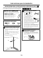
REMOVE ICE CUBE TRAY SHELF
• Remove the two screws securing the ice cube tray
to the side wall of the freezer. Remove the tray.
• There are two white plug buttons above the screw
holes. Remove these plug buttons and install
them in the two screw holes that were used to
hold the ice cube tray shelf.
• Install two Phillips head screws (11) in the holes
that the plug buttons were in, but do not screw
them all the way in. The screw heads should
extend about 1/2″ (13 mm) from the side wall
of the freezer.
18
Installation Instructions
ICEMAKER INSTALLATION INSTRUCTIONS N
Are these the right instructions for your model? Follow the Installation Instructions indicated by
the label on the back of the refrigerator--- or
SRQPNML
BEFORE YOU BEGIN
Read each step thoroughly before proceeding.
•
CAUTION – Unplug the
Refrigerator. To eliminate the danger
of electric shock during installation,
you must unplug the refrigerator from
its electrical outlet.
Flat blade and Phillips
screwdrivers
Pliers
TOOLS YOU WILL NEED
Sharp knife
2
PREPARE FOR INSTALLATION
• Remove and discard the large white plug from
the rear freezer wall. Pull out the gray insulation
plug and remove any debris.
• Remove the outlet cover with a flat-blade
screwdriver.
1
Plug
Buttons
11
INSTALL FILL TUBE
• Slide the fill tube with foil (14)
onto the water tube inlet (12),
making sure that the open side
of the fill tube faces up.
• Go to the back of the
refrigerator. On the tube side
of the water tube inlet (12),
there is an adhesive backing.
Remove the adhesive backing
and slide the tube into the hole
near the top at the back of the
refrigerator. Firmly press on the
inlet to secure it to the refrigerator.
• Install the water tube
inlet cover (17) over
the water tube inlet.
Secure the cover
using two hex-head
screws (18).
3
12
14

19
Installation Instructions
SET POWER SWITCH TO O (off)
Set the icemaker power switch to O (off). Leave
the power switch in the O (off) position until the
refrigerator is connected to the water supply to
prevent premature operation.
4
Power
Switch
INSTALLTHE ICEMAKERFILLCUP
Install the icemaker fill cup (side-mounted) (15)
into the icemaker as shown.
5
15
PLUG IN THE ICEMAKER
Holding the icemaker in place, insert the icemaker
power cord plug into the socket on the rear wall,
making sure the prongs and holes are matched.
Press the plug firmly into the socket. Lock the plug
in place by clipping the restraints onto each side of
the plug. Make sure the restraints click into place.
Make sure the power cord is still in the hook on the
back of the icemaker.
6
MOUNT THE ICEMAKER
• Lift the icemaker so the fill tube (14) goes into the
fill cup opening (15). Hang the icemaker on the
two mounting screws (11).
Make sure:
• The power cord is still firmly in the socket.
• The fill tube (14) extends into the fill cup
opening at the back of the icemaker. (Check
the rear of the refrigerator to make sure the fill
tube has not been pushed out of the back of
the refrigerator).
• The icemaker mounting screws are located in
the uppermost position of the mounting slots.
• The icemaker is level.
THEN SECURELY TIGHTEN THE ICEMAKER
MOUNTING SCREWS.
7
14
15
INSTALL THE ICE BUCKET
Place the ice bucket (9) under the icemaker.
Make sure the icemaker power switch is set to O (off).
8
9
ATTACH WARRANTY LABEL
A label (7) is provided with this kit to record the
date of installation for warranty purposes. Apply it
to the back of the refrigerator.
9
KEEP THIS MANUAL
The warranty for the icemaker is printed in this
manual. Keep this manual with your Refrigerator
Owner’s Manual.
The icemaker installation inside the freezer is now
complete. Continue to the Water Valve Assembly
section.
10
11
Hook

20
Installation Instructions
BEFORE YOU BEGIN
Read each step thoroughly before proceeding.
•
CAUTION – Unplug the
Refrigerator. To eliminate the danger
of electric shock during installation,
you must unplug the refrigerator
from its electrical outlet.
WATER VALVE ASSEMBLY INSTALLATION INSTRUCTIONS N
Are these the right instructions for your model? Follow the Installation Instructions indicated by
the label on the back of the refrigerator--- or
SRQPNML
Flat blade and Phillips
screwdrivers
Pliers
TOOLS YOU WILL NEED
Sharp knife
1/4″ and 5/16″ Nutdrivers
ATTACH THE WATER VALVE
• Locate the female connector plug. Plug the
female connector (C) onto the male terminals
on the water valve (3). Either wire can go on
either terminal.
2
10
• Fasten the water valve to the cabinet by driving
the hex-head screw (10) from the kit into the
hole in the cabinet leg.
C
3
REMOVE THE COVER
Use a 5/16″ nutdriver or an adjustable wrench to
remove the compressor compartment access cover.
This requires removing six screws which attach the
cover to the back of the refrigerator case.
Be sure to save the screws as the access cover must
be reinstalled later to ensure your refrigerator will
function properly.
1
La page est en cours de chargement...
La page est en cours de chargement...
La page est en cours de chargement...
La page est en cours de chargement...
La page est en cours de chargement...
La page est en cours de chargement...
La page est en cours de chargement...
La page est en cours de chargement...
La page est en cours de chargement...
La page est en cours de chargement...
La page est en cours de chargement...
La page est en cours de chargement...
La page est en cours de chargement...
La page est en cours de chargement...
La page est en cours de chargement...
La page est en cours de chargement...
La page est en cours de chargement...
La page est en cours de chargement...
La page est en cours de chargement...
La page est en cours de chargement...
La page est en cours de chargement...
La page est en cours de chargement...
La page est en cours de chargement...
La page est en cours de chargement...
La page est en cours de chargement...
La page est en cours de chargement...
La page est en cours de chargement...
La page est en cours de chargement...
La page est en cours de chargement...
La page est en cours de chargement...
La page est en cours de chargement...
La page est en cours de chargement...
La page est en cours de chargement...
La page est en cours de chargement...
La page est en cours de chargement...
La page est en cours de chargement...
La page est en cours de chargement...
La page est en cours de chargement...
La page est en cours de chargement...
La page est en cours de chargement...
La page est en cours de chargement...
La page est en cours de chargement...
La page est en cours de chargement...
La page est en cours de chargement...
La page est en cours de chargement...
La page est en cours de chargement...
La page est en cours de chargement...
La page est en cours de chargement...
La page est en cours de chargement...
La page est en cours de chargement...
La page est en cours de chargement...
La page est en cours de chargement...
La page est en cours de chargement...
La page est en cours de chargement...
La page est en cours de chargement...
La page est en cours de chargement...
La page est en cours de chargement...
La page est en cours de chargement...
La page est en cours de chargement...
La page est en cours de chargement...
La page est en cours de chargement...
La page est en cours de chargement...
La page est en cours de chargement...
La page est en cours de chargement...
La page est en cours de chargement...
La page est en cours de chargement...
La page est en cours de chargement...
La page est en cours de chargement...
La page est en cours de chargement...
La page est en cours de chargement...
La page est en cours de chargement...
La page est en cours de chargement...
La page est en cours de chargement...
La page est en cours de chargement...
La page est en cours de chargement...
La page est en cours de chargement...
La page est en cours de chargement...
La page est en cours de chargement...
La page est en cours de chargement...
La page est en cours de chargement...
La page est en cours de chargement...
La page est en cours de chargement...
La page est en cours de chargement...
La page est en cours de chargement...
La page est en cours de chargement...
La page est en cours de chargement...
La page est en cours de chargement...
La page est en cours de chargement...
La page est en cours de chargement...
La page est en cours de chargement...
La page est en cours de chargement...
La page est en cours de chargement...
La page est en cours de chargement...
La page est en cours de chargement...
La page est en cours de chargement...
La page est en cours de chargement...
La page est en cours de chargement...
La page est en cours de chargement...
La page est en cours de chargement...
La page est en cours de chargement...
La page est en cours de chargement...
La page est en cours de chargement...
La page est en cours de chargement...
La page est en cours de chargement...
La page est en cours de chargement...
La page est en cours de chargement...
La page est en cours de chargement...
La page est en cours de chargement...
La page est en cours de chargement...
La page est en cours de chargement...
La page est en cours de chargement...
La page est en cours de chargement...
La page est en cours de chargement...
La page est en cours de chargement...
La page est en cours de chargement...
La page est en cours de chargement...
-
 1
1
-
 2
2
-
 3
3
-
 4
4
-
 5
5
-
 6
6
-
 7
7
-
 8
8
-
 9
9
-
 10
10
-
 11
11
-
 12
12
-
 13
13
-
 14
14
-
 15
15
-
 16
16
-
 17
17
-
 18
18
-
 19
19
-
 20
20
-
 21
21
-
 22
22
-
 23
23
-
 24
24
-
 25
25
-
 26
26
-
 27
27
-
 28
28
-
 29
29
-
 30
30
-
 31
31
-
 32
32
-
 33
33
-
 34
34
-
 35
35
-
 36
36
-
 37
37
-
 38
38
-
 39
39
-
 40
40
-
 41
41
-
 42
42
-
 43
43
-
 44
44
-
 45
45
-
 46
46
-
 47
47
-
 48
48
-
 49
49
-
 50
50
-
 51
51
-
 52
52
-
 53
53
-
 54
54
-
 55
55
-
 56
56
-
 57
57
-
 58
58
-
 59
59
-
 60
60
-
 61
61
-
 62
62
-
 63
63
-
 64
64
-
 65
65
-
 66
66
-
 67
67
-
 68
68
-
 69
69
-
 70
70
-
 71
71
-
 72
72
-
 73
73
-
 74
74
-
 75
75
-
 76
76
-
 77
77
-
 78
78
-
 79
79
-
 80
80
-
 81
81
-
 82
82
-
 83
83
-
 84
84
-
 85
85
-
 86
86
-
 87
87
-
 88
88
-
 89
89
-
 90
90
-
 91
91
-
 92
92
-
 93
93
-
 94
94
-
 95
95
-
 96
96
-
 97
97
-
 98
98
-
 99
99
-
 100
100
-
 101
101
-
 102
102
-
 103
103
-
 104
104
-
 105
105
-
 106
106
-
 107
107
-
 108
108
-
 109
109
-
 110
110
-
 111
111
-
 112
112
-
 113
113
-
 114
114
-
 115
115
-
 116
116
-
 117
117
-
 118
118
-
 119
119
-
 120
120
-
 121
121
-
 122
122
-
 123
123
-
 124
124
-
 125
125
-
 126
126
-
 127
127
-
 128
128
-
 129
129
-
 130
130
-
 131
131
-
 132
132
-
 133
133
-
 134
134
-
 135
135
-
 136
136


dans d''autres langues
- English: GE GEIM4A User manual
- español: GE GEIM4A Manual de usuario
Documents connexes
-
GE GEIM4A Guide d'installation
-
-
GE IM6D Le manuel du propriétaire
-
GE IM-5A Le manuel du propriétaire
-
-
-
-
-
-