
PD-E
English en
Français fr
Español es
Português pt
Printed: 13.06.2016 | Doc-Nr: PUB / 5151888 / 000 / 02

1
Printed: 13.06.2016 | Doc-Nr: PUB / 5151888 / 000 / 02

2
3
4
Printed: 13.06.2016 | Doc-Nr: PUB / 5151888 / 000 / 02

PD-E
en English . . . . . . . . . . . . . . . . . . . . . . . . . . . . . . . . . . . . . . . . . . . . . . . . . . . . . . 1
fr Français . . . . . . . . . . . . . . . . . . . . . . . . . . . . . . . . . . . . . . . . . . . . . . . . . . . . 12
es Español . . . . . . . . . . . . . . . . . . . . . . . . . . . . . . . . . . . . . . . . . . . . . . . . . . . . . 24
pt Português . . . . . . . . . . . . . . . . . . . . . . . . . . . . . . . . . . . . . . . . . . . . . . . . . . . 36
Printed: 13.06.2016 | Doc-Nr: PUB / 5151888 / 000 / 02

1
1 Information about the documentation
1.1 Conventions
1.1.1 Warning signs
The following warning signs are used:
DANGER! Draws attention to imminent danger that will lead to serious personal injury or fatality.
WARNING! Draws attention to a potentially dangerous situation that could lead to serious per-
sonal injury or fatality.
CAUTION! Draws attention to a potentially dangerous situation that could lead to slight personal
injury or damage to the equipment or other property.
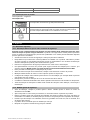
1.1.2 Symbols
The following symbols are used:
Read the operating instructions before use.
KCCREM-HLTPD-E
On/off button
Measure button
Menu button
Delete (clear) button
Right arrow button
Left arrow button
1.1.3 Typographical emphasis
The following typographic features are used to emphasize important passages in this technical documenta-
tion:
1
These numbers refer to the corresponding illustrations.
1.2 About this documentation
▶ It is essential that the operating instructions are read before initial operation.
▶ The information provided in the detailed operating instructions installed in the tool as well as the
supplements and updates provided at www.hilti.com must also be observed.
▶ Always keep these operating instructions together with the tool.
▶ Ensure that the operating instructions are with the tool when it is given to other persons.
1.3 Product information
Hilti products are designed for professional use and may be operated, serviced and maintained only by
trained, authorized personnel. This personnel must be informed of any particular hazards that may be
encountered. The product and its ancillary equipment may present hazards when used incorrectly by
untrained personnel or when used not as directed.
The type designation and serial number are printed on the rating plate.
▶ Write down the serial number in the table below. You will be required to state the product details when
contacting Hilti Service or your local Hilti organization to enquire about the product.
Product information
Laser range meter PD-E
Generation 01
Printed: 13.06.2016 | Doc-Nr: PUB / 5151888 / 000 / 02

2
Serial no.
1.4 Laser information on the product
Laser information → page 2
Laser information
Laser Class 2 based on the IEC60825-1 / EN60825-1:2007 standard in com-
pliance with CFR 21 § 1040 (Laser Notice 50).
Laser Class 2: Do not stare into the beam. Do not direct the beam toward
other persons or toward areas in which other persons, who are not involved in
the work with lasers, may be present.
Recycle waste material.
2 Safety
2.1 Safety instructions
2.1.1 Basic information concerning safety
In addition to the safety rules listed in the individual sections of these operating instructions, the
following rules must be strictly observed at all times. The product and its ancillary equipment may
present hazards when used incorrectly by untrained personnel or when used not as directed.
▶ Keep all safety instructions and information for future reference.
▶ Stay alert, watch what you are doing and use common sense when working with the product. Do not
use the product while you are tired or under the influence of drugs, alcohol or medication. A moment of
inattention while operating the product may result in serious personal injury.
▶ Do not render safety devices ineffective and do not remove information and warning notices.
▶ If the product is opened improperly, laser radiation in excess of Class 2 may be emitted. Have the
product repaired only by Hilti Service.
▶ Tampering with or modification of the product is not permitted.
▶ Check that the product functions correctly each time before use.
▶ Measurements taken through panes of glass or other objects may be inaccurate.
▶ The measurement may be incorrect if the conditions under which the measurement is taken change
rapidly, e.g. due to people walking through the path of the laser beam.
▶ Do not point the product toward the sun or other powerful light sources.
▶ Take the influences of the surrounding area into account. Do not use the tool where there is a risk of fire
or explosion.
▶ Observe the information printed in the operating instructions concerning operation, care and maintenance.
2.1.2 General safety rules
▶ Check the product for damage before use. Have the damage repaired by Hilti Service.
▶ Check the accuracy of the product after it has been dropped or subjected to other mechanical stresses.
▶ Although the product is designed for the tough conditions of jobsite use, as with other measuring
instruments it should be treated with care.
▶ Products which are not in use must be stored in a dry, high place or locked away out of reach of children.
▶ The product is not intended for use by children.
▶ Observe the national health and safety requirements.
2.1.3 Proper preparation of the working area
▶ Avoid unfavorable body positions when working from ladders. Make sure you have a safe stance and
that you stay in balance at all times.
▶ Secure the site at which you are taking measurements and take care to avoid directing the laser beam
toward other persons or toward yourself.
Printed: 13.06.2016 | Doc-Nr: PUB / 5151888 / 000 / 02

3
▶ When the product is brought into a warm environment from very cold conditions, or vice-versa, allow it
to become acclimatized before use.
▶ Use the product only within its specified limits.
▶ Keep the laser exit window clean in order to avoid measurement errors.
▶ Observe the accident prevention regulations applicable in your country.
2.1.4 Working safely with laser tools
▶ Laser Class 2/Class II tools may be operated only by appropriately trained persons.
▶ Laser beams should not be projected at eye height.
▶ Precautions must be taken to ensure that the laser beam does not unintentionally strike highly reflective
surfaces.
▶ Precautions must be taken to ensure that persons do not stare directly into the beam.
▶ The laser beam must not be allowed to project beyond the controlled area.
▶ Switch the laser tool off when it is not in use.
▶ Store laser tools, when not in use, in places to which unauthorized persons have no access.
2.1.5 Electromagnetic compatibility
Although the device complies with the strict requirements of the applicable directives, Hilti cannot entirely
rule out the possibility of interference to the device caused by powerful electromagnetic radiation, possibly
leading to incorrect operation. Check the accuracy of the device by taking measurements by other means
when working under such conditions or if you are unsure. Likewise, Hilti cannot rule out the possibility of
interference with other devices (e.g. aircraft navigation equipment). The tool complies with the requirements
of class A; The possibility of interference occurring in a domestic environment cannot be excluded.
Only for Korea: This laser range meter is suitable for commercial and industrial use and for the electromagnetic
radiation encountered in this field (Class A). Users must pay attention to this point and make sure that this
laser range meter is not used in occupied living areas.
3 Description
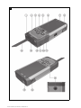
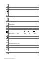
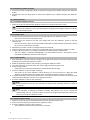
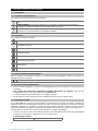
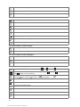
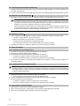
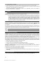
3.1 Overview of the product 1
@
Rear contact surface
;
Reference indicator LED for rear contact
=
Left arrow button
%
Menu button
&
“Measure” button
(
Graphic display
)
Reference indicator LED for front contact
+
Side “Measure” button
§
On/off button
/
Right arrow button
:
Hand strap attachment point
∙
Delete (clear) button
$
¹/₄ inch thread
£
Folding spike
|
Laser emitting and receiving lens
¡
Optical sight
Q
¹/₄ inch thread
3.2 Intended use
The product described is a laser range meter. It is designed for taking individual measurements as well as
the continuous measurement of distances.
Distances can be measured from all stationary targets without a highly reflective surface, i.e. concrete,
stone, wood, plastic, paper, etc. The use of prisms or other highly reflective targets is not permissible and, if
attempted, may falsify the results.
The product is approved for use with batteries of the type AAA.
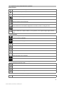
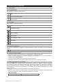
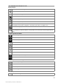
3.3 Explanation of the display
Main menu
Select angle unit
Determine painter’s area
Single Pythagoras
Printed: 13.06.2016 | Doc-Nr: PUB / 5151888 / 000 / 02

4
Measure areas and volumes
Select special functions
Select trapezoid function
Select Pythagoras function
At least one right angle is required for horizontal and diagonal distances.
Select settings
Measure indirectly
No specific angle is required for measurements on non-moving objects such as walls.
Generally applicable symbols
Battery charge state
Measuring spike not folded out
Measuring spike folded out
Measure
Add distances
Subtract distances
Select
Do not select
Select measuring time
Select calculator
Angle units submenu
Inclination in percent
Metric units
Imperial units
Inclination in angular degrees
Area and volume measurement submenu
Measure rectangular areas
Measure triangular areas
Measure volumes
Measure cylinder volume
Special functions submenu
Select outdoor mode
Printed: 13.06.2016 | Doc-Nr: PUB / 5151888 / 000 / 02

5
Select automatic brightness sensor
Determine area to be painted
Select layout function
Select min/max delta function
Select timer
Select offset function
Select data storage media
Trapezoid function submenu
Measure 3 distances
Measure 2 distances, 1 angle
Pythagoras function submenu
Single Pythagoras
Double Pythagoras
Combined Pythagoras
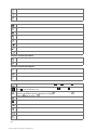
Settings submenu
Unit of measurement. Select unit of measurement: meter centimeter millimeter
Measuring references. Select measuring reference: front edge rear of thread underside of
thread
Angle unit. Select angle unit: inclination in percent metric units imperial units inclination
in angular degrees
Select expert mode
Edit favorites list
Activate scale
Switch signal tone on / off
Select laser on constantly
Select automatic brightness sensor
Calibrate inclination sensor
Display information about the tool
Reset to default settings
Indirect measurement submenu
Indirect horizontal distance measurement
Printed: 13.06.2016 | Doc-Nr: PUB / 5151888 / 000 / 02

6
Indirect vertical distance measurement
Take measurements on ceilings
Indirect vertical distance measurement II
3.4 Items supplied
Laser range meter, two batteries, operating instructions, manufacturer’s certificate.
Note
You can find other system products approved for use with your product at your local Hilti Center or
online at: www.hilti.com.
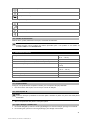
4 Technical data
Operating temperature
−10 ℃ … 50 ℃
(14 ℉ … 122 ℉)
Distance measurement accuracy (2σ, standard deviation)
±1.0 mm
Inclination measurement accuracy (2σ, standard deviation)
±0.2°
Weight (including batteries)
165 g
(5.8 oz)
Storage temperature
−30 ℃ … 70 ℃
(−22 ℉ … 158 ℉)
Laser class in accordance with EN 60825-1:2007
Laser class 2
Protection class in accordance with IEC 60529
IP 65
Power source
1.5 V
5 Operation
5.1 Basic functions
Navigate to the desired function with the aid of the left or right arrow buttons.
▶ Always press the “Measure” button to select a function.
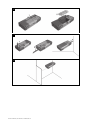
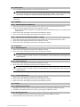
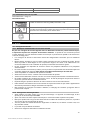
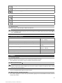
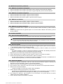
5.2 Inserting the batteries 2
Note
Take care to ensure correct battery polarity. Change the batteries only in pairs. Do not use damaged
batteries.
▶ Open the battery compartment and insert the batteries.
5.3 Switching the laser range meter on and off
1. If the tool is switched off, press the on/off button or the “Measure” button to switch it on.
2. If the tool is switched on, press the on/off button to switch it off.
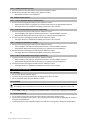
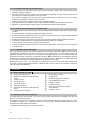
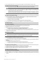
5.4 Measuring using the spike 3
1. Fold out the spike through 90°. The spike can then be used as the contact point.
Note
Here, the spike helps to align the device while a stable position is established. This is the case
primarily for indirect, trapezoid and Pythagoras measurements since these results are based on
estimated values.
Use the measuring extension PDA 72 for inaccessible places. The device automatically detects
the measuring extension. A confirmation window may appear in the display.
Printed: 13.06.2016 | Doc-Nr: PUB / 5151888 / 000 / 02

7
2. Fold out the spike through 180°. The measuring reference point is then set automatically.
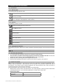
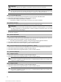
5.5 Measuring using a target plate 4
1. Use the target plate to measure distance under the following unfavorable conditions:
◁ The wall is not sufficiently reflective due to the type of surface.
◁ The target point is not on a surface.
◁ The distance to be measured is very long.
◁ The light conditions are unfavorable (bright sunshine).
2. A distance of 1.2 mm should be added to the measured distance when using a target plate.
5.6 Measurement mode
5.6.1 Single measurements
1. Press the “Measure” button briefly to activate the laser beam.
2. Keep the laser beam on the target point.
3. Press the “Measure” button briefly to take the measurement.
◁ The measured distance is shown in the lower line of the display.
◁ The distance measured in the previous measurement is shown in the upper line of the display.
4. To take another measurement, keep the laser beam on the target point and press the “Measure” button
again.
5.6.2 Continuous measurement
Note
During continuous measurement, 6-10 measurements are taken and displayed every second. The
laser range meter can be moved relative to the target until the desired distance is reached.
1. Press the “Measure” button for 2 seconds.
◁ If the signal tone is active, a signal tone will be emitted.
2. Move the laser range meter toward or away from the target until the desired distance is reached.
3. Press the “Measure” button briefly.
◁ The measured distance is shown in the lower line of the display.
◁ The distance measured in the previous measurement is shown in the upper line of the display.
5.7 Selecting the angle unit
1. Select the angle unit symbol from the menu.
2. Navigate to the desired angle unit with the aid of the left or right arrow buttons.
3. Select the desired angle unit by pressing the “Measure” button.
5.8 Measuring areas and volumes
5.8.1 Measuring rectangular areas
1. Aim the tool at the target point for the room width and press the “Measure” button.
2. Aim the tool at the target point for the room length and press the “Measure” button.
5.8.2 Measuring triangular areas
1. Aim the tool at the target point and press the “Measure” button.
2. Aim the tool at the target point and press the “Measure” button.
3. Aim the tool at the third target point and press the “Measure” button.
5.8.3 Measuring volumes
1. Aim the tool at the target point and press the “Measure” button.
2. Aim the tool at the next target point and press the “Measure” button.
3. Aim the tool at the next target point and press the “Measure” button.
Printed: 13.06.2016 | Doc-Nr: PUB / 5151888 / 000 / 02

8
5.8.4 Measuring cylindrical volume
1. Aim the tool at the corresponding target to measure the height of the cylinder and press the “Measure”
button.
2. Aim the tool at the next target point to measure the diameter of the cylinder and press the “Measure”
button.
5.9 Special functions
5.9.1 Automatic brightness sensor
▶ Select the symbol for the automatic brightness sensor from the special functions menu.
Note
The automatic brightness sensor automatically dims the lighting on the display in dark surroundings.
This saves battery power.
5.9.2 Painter’s area
1. Aim the tool at the target point for the first room length and press the “Measure” button.
◁ The result is saved as an intermediate result.
2. Aim the tool at the target for the next room length and press the “Measure” button to take the
measurement.
◁ The second result is shown in the intermediate results table. The intermediate result shown in bold is
the sum of the measured room lengths.
3. Repeat this procedure until all room lengths have been measured.
4. Press the right arrow button to switch to room height and confirm by pressing the “Measure” button.
5. Position and aim the tool for room height measurement and then take the measurement.
◁ The room height is measured and displayed in the intermediate result line. The painter’s area is
calculated immediately and shown in the result line.
5.9.3 Layout function
1. Enter the distance manually. Do this by using the left or right arrow buttons to select the keyboard symbol
and confirm by pressing the “Measure” button.
2. Select the applicable numbers and confirm by pressing the “Measure” button.
3. To confirm the value, select the check mark symbol (tick) at the bottom right corner.
4. Select the flag symbol.
◁ The distance you have entered will then be shown between the two flags.
5. Press the “Measure” button to begin measuring.
◁ The arrows on the screen indicate in which direction you must move the tool. When the target
distance is reached, black arrows appear above and below the distance shown in the display.
6. To repeat this distance measurement several times, move the tool further. The number of times you have
measured out this distance is shown on the right of the screen.
7. Press the “Measure” button to stop measuring.
Note
When the distance to be set out is reached, the currently used measuring reference is shown in
the display.
Note
As an alternative to entering the distance manually, the distance to be set out may also be
measured with the tool. To do this, select the symbol for single measurement and confirm your
choice by pressing the “Measure” button.
5.9.4 Min/max delta function
1. Select the symbol for the min/max delta function from the special functions menu.
2. Aim the tool at the target point and press the “Measure” button.
3. Press the “Measure” button to stop measuring.
◁ The last distances measured are shown in the results line.
Printed: 13.06.2016 | Doc-Nr: PUB / 5151888 / 000 / 02

9
5.9.5 Data storage
1. Select the data storage symbol from the special functions menu.
Note
The tool can save up to 30 screens, including the graphical symbols. If 30 screens have already
been saved, the oldest one will be deleted automatically when a new screen is saved.
2. To delete data storage memory, press and hold the C-button for 2 seconds while the data storage screen
is displayed.
5.10 Trapezoid
5.10.1 Trapezoid function (3 distances)
1. Select the symbol for the trapezoid function for 3 distances from the trapezoid functions menu.
2. Aim the tool at the target point and press the “Measure” button.
◁ After measuring the first distance, the graphical display automatically prompts you to take the next
measurement.
3. Aim the tool at the next target point and press the “Measure” button.
4. Aim the tool at the third target point and press the “Measure” button.
5.10.2 Trapezoid with inclination (2 distances, 1 angle)
1. Select the symbol for the trapezoid function with inclination from the trapezoid functions menu.
2. Aim the tool at the target point and press the “Measure” button.
3. Aim the tool at the next target point and press the “Measure” button.
5.11 Pythagoras
5.11.1 Single Pythagoras
1. Aim the tool at the target point and press the “Measure” button.
2. Aim the tool at the next target point and press the “Measure” button.
Note
In order to achieve accurate results, the second distance must be measured at right angles to the
target distance.
5.11.2 Double Pythagoras
1. Aim the tool at the target point and press the “Measure” button.
2. Aim the tool at the next target point and press the “Measure” button.
Note
In order to achieve accurate results, the second distance must be measured at right angles to the
target distance.
3. Aim the tool at the third target point and press the “Measure” button.
5.11.3 Combined Pythagoras
1. Aim the tool at the target point and press the “Measure” button.
2. Aim the tool at the next target point and press the “Measure” button.
3. Aim the tool at the next target point and press the “Measure” button.
5.12 Settings
5.12.1 Editing the favorites list
1. Navigate to the function that you wish to edit and confirm by pressing the “Measure” button.
2. Navigate to the desired function and confirm by pressing the “Measure” button.
5.12.2 Activating the scale
1. Set the applicable number and confirm the value by pressing the “Measure” button.
2. Select the check mark symbol (tick) to confirm the value.
Printed: 13.06.2016 | Doc-Nr: PUB / 5151888 / 000 / 02

10
5.12.3 Calibrate inclination sensor
1. Place the tool on a horizontal surface and press the “Measure” button.
2. Rotate the tool through 180° and press the “Measure” button.
◁ The inclination sensor is now calibrated.
5.13 Indirect measurements
5.13.1 Indirect horizontal distance measurement
▶ Aim the tool at the target point and press the “Measure” button.
◁ The distance and angle of inclination are measured and shown in the intermediate result line.
◁ The target distance is calculated immediately and shown in the result line.
5.13.2 Indirect vertical distance (2 angles, 2 distances)
1. Aim the tool at the target point and press the “Measure” button.
◁ The first distance and angle are measured and shown in the intermediate result line.
◁ The graphical display automatically prompts you to measure the second distance.
2. Aim the tool at the next target point and press the “Measure” button.
◁ The target distance is calculated immediately and shown in the result line.
5.13.3 Taking measurements on ceilings
1. Aim the tool at the target point and press the “Measure” button.
◁ The first distance and angle are measured and shown in the intermediate result line.
◁ The graphical display automatically prompts you to measure the second distance.
2. Aim the tool at the next target point and press the “Measure” button.
◁ The target distance is calculated immediately and shown in the result line.
5.13.4 Indirect vertical distance II (2 angles, 1 distance)
1. Aim the tool at the target point and press the “Measure” button.
◁ The first distance and angle are measured and shown in the intermediate result line.
◁ The graphical display automatically prompts you to measure the second distance.
2. Aim the tool at the next target point and press the “Measure” button.
◁ The target distance is calculated immediately and shown in the result line.
6 Care, transport and storage
6.1 Cleaning
▶ Do not touch the lens with the fingers.
▶ Clean the lens by blowing the dust off or by wiping with a clean, dry cloth.
▶ Do not use liquids other than pure alcohol or water.
6.2 Transport
Note
The batteries must be insulated or removed from the product before it is shipped or sent by mail.
▶ Use the Hilti packaging or packaging of equivalent quality for transporting or shipping your equipment.
6.3 Storage and drying
▶ Do not put the product into storage when wet. Allow it to dry before putting it away.
▶ Observe the temperature limits given in the Technical Data section which are applicable to storage or
transport of the equipment.
▶ Check the accuracy of the equipment before it is used after a long period of storage or transportation.
Printed: 13.06.2016 | Doc-Nr: PUB / 5151888 / 000 / 02

11
7 Disposal
WARNING
Risk of injury. Hazards presented by improper disposal.
▶ Improper disposal of the equipment may have the following consequences: The burning of plastic
components generates toxic fumes which may present a health hazard. Batteries may explode
if damaged or exposed to very high temperatures, causing poisoning, burns, acid burns or
environmental pollution. Careless disposal may permit unauthorized and improper use of the
equipment. This may result in serious personal injury, injury to third parties and pollution of the
environment.
Most of the materials from which Hilti products are manufactured can be recycled. The materials must be
correctly separated before they can be recycled. In many countries, your old tools, machines or appliances
can be returned to Hilti for recycling. Ask Hilti Service or your Hilti representative for further information.
In accordance with the European Directive on waste electrical and electronic equipment and its implemen-
tation in conformance with national law, electric tools or appliances that have reached the end of their life
must be collected separately and returned to an environmentally compatible recycling facility.
▶ Disposal of electric tools or appliances together with household waste is not permissible.
8 FCC statement / IC statement
CAUTION This product has been tested and found to comply with the limits for a class B digital device,
pursuant to part 15 of the FCC Rules. These limits are designed to provide reasonable protection against
harmful interference in a residential installation. These products generate, use and can radiate radio
frequency energy and, if not installed and used in accordance with the instructions, may cause interference
to radio communications.
There is no guarantee that interference will not occur in a particular installation. If this product does cause
harmful interference to radio or television reception, which can be determined by turning the product off and
on, the user is encouraged to try to correct the interference by taking the following measures:
▶ Re-orient or move the receiving antenna.
▶ Increase the distance between the product and receiver.
▶ Connect the product to a power outlet on a circuit different from that to which the receiver is connected.
▶ Consult your dealer or an experienced TV/radio technician for assistance.
Changes or modifications not expressly approved by Hilti may restrict the user’s right to operate the product.
This product complies with the requirements in Paragraph 15 of the FCC Rules and RSS 210 of IC.
Operation of the product is subject to the following conditions:
▶ This product should cause no harmful interference.
▶ This product must accept any interference received, including interference that may cause undesired
operation.
9 Manufacturer’s warranty
▶ Please contact your local Hilti representative if you have questions about the warranty conditions.
Printed: 13.06.2016 | Doc-Nr: PUB / 5151888 / 000 / 02

12
1 Indications relatives à la documentation
1.1 Conventions
1.1.1 Symboles d'avertissement
Les symboles d'avertissement suivants sont utilisés :
DANGER ! Pour un danger imminent qui peut entraîner de graves blessures corporelles ou la
mort.
AVERTISSEMENT ! Pour attirer l'attention sur une situation pouvant présenter des dangers
susceptibles d'entraîner des blessures corporelles graves ou la mort.
ATTENTION ! Pour attirer l'attention sur une situation pouvant présenter des dangers entraînant
des blessures corporelles légères ou des dégâts matériels.
1.1.2 Symboles
Les symboles suivants sont utilisés :
Lire le mode d'emploi avant d'utiliser l'appareil
KCCREM-HLTPD-E
Bouton Marche / Arrêt
Touche de mesure
Touche de menu
Touche Effacement (Clear)
Touche droite
Touche gauche
1.1.3 Mises en évidence typographiques
Dans la présente documentation technique, les caractéristiques typographiques mettent en évidence les
passages de textes importants :
1
Les chiffres renvoient aux illustrations respectives.
1.2 À propos de cette documentation
▶ Avant de mettre l'appareil en marche, lire impérativement son mode d'emploi et bien respecter les
consignes.
▶ Tenir compte des instructions d'utilisation complètes disponibles sur l'appareil, ainsi que des
compléments et mises à jour disponibles sous www.hilti.com.
▶ Le présent mode d'emploi doit toujours accompagner l'appareil.
▶ Ne pas prêter ou céder l'appareil à un autre utilisateur sans lui fournir le mode d'emploi.
1.3 Informations produit
Les produits Hilti sont conçus pour les utilisateurs professionnels et ne doivent être utilisés, entretenus et
réparés que par un personnel agréé et formé à cet effet. Ce personnel doit être au courant des dangers
inhérents à l'utilisation de l'appareil. Le produit et ses accessoires peuvent s'avérer dangereux s'ils sont
utilisés de manière incorrecte par un personnel non qualifié ou de manière non conforme à l'usage prévu.
La désignation du modèle et le numéro de série figurent sur sa plaque signalétique.
▶ Inscrivez le numéro de série dans le tableau suivant. Les informations produit vous seront demandées
lorsque vous contactez nos revendeurs ou services après-vente.
Caractéristiques produit
Lasermètre PD-E
Printed: 13.06.2016 | Doc-Nr: PUB / 5151888 / 000 / 02

13
Génération 01
N° de série
1.4 Informations laser sur le produit
Informations laser → Page 13
Informations laser
Classe laser 2, satisfaisant aux exigences des normes IEC60825-1/EN60825-
1:2007 et conforme à CFR 21 § 1040 (notice laser n° 50).
Classe laser 2. Ne pas regarder dans le faisceau. Ne pas diriger le faisceau
vers des tierces personnes ou dans des zones où peuvent se trouver d'autres
personnes non concernées par les travaux laser.
Recycler les déchets.
2 Sécurité
2.1 Consignes de sécurité
2.1.1 Remarques fondamentales concernant la sécurité
En plus des consignes de sécurité figurant dans les différentes sections du présent mode d'emploi,
il importe de toujours bien respecter les directives suivantes. Le produit et ses accessoires peuvent
s'avérer dangereux s'ils sont utilisés de manière incorrecte par un personnel non qualifié ou de manière non
conforme à l'usage prévu.
▶ Les consignes de sécurité et instructions doivent être intégralement conservées pour les utilisations
futures.
▶ Restez vigilant, surveillez ce que vous faites. Faites preuve de bon sens en utilisant le produit. Ne pas
utiliser le produit en étant fatigué ou sous l'emprise de drogues, de l'alcool ou de médicaments. Un
moment d'inattention lors de l'utilisation du produit peut entraîner des blessures graves.
▶ Ne pas neutraliser les dispositifs de sécurité ni enlever les plaquettes indicatrices et les plaquettes
d'avertissement.
▶ En cas d'ouverture incorrecte du produit, il peut se produire un rayonnement laser d'intensité supérieure
à celle des appareils de classe 2. Faire réparer le produit exclusivement par le S.A.V. Hilti.
▶ Toute manipulation ou modification du produit est interdite.
▶ Avant toute mise en service, contrôler le bon fonctionnement du produit.
▶ Toutes mesures effectuées à travers une vitre ou tout autre objet peuvent fausser le résultat de mesure.
▶ De rapides variations des conditions de mesure, par ex. du fait du passage d'une personne devant le
rayon laser, peuvent fausser le résultat de mesure.
▶ Ne jamais diriger le produit en direction du soleil ou d'autres sources de lumière intense.
▶ Prêter attention aux influences de l'environnement de l'espace de travail. Ne pas utiliser l'appareil dans
des endroits présentant un danger d'incendie ou d'explosion.
▶ Bien respecter les consignes concernant l'utilisation, le nettoyage et l'entretien qui figurent dans le
présent mode d'emploi.
2.1.2 Consignes de sécurité générales
▶ Avant d’utiliser le produit, vérifier qu'il n'est pas endommagé. Si l'appareil est endommagé, le faire
réparer par le service de réparation Hilti.
▶ Après une chute ou d'autres impacts mécaniques, il convient de vérifier la précision du produit.
▶ Bien que le produit soit conçu pour être utilisé dans les conditions de chantier les plus dures, en prendre
soin comme de tout autre appareil de mesure.
▶ Tous les produits non utilisés doivent être rangés dans un endroit sec, en hauteur ou fermé à clé, hors
de portée des enfants.
▶ Le produit n'est pas destiné aux enfants.
▶ Observer les exigences nationales en matière de sécurité.
Printed: 13.06.2016 | Doc-Nr: PUB / 5151888 / 000 / 02

14
2.1.3 Installation appropriée du poste de travail
▶ Lors de travaux sur une échelle, éviter toute posture anormale. Veiller à tout moment à une bonne
stabilité et à garder l'équilibre.
▶ Sécuriser le site de mesure et veiller, lors de toute utilisation du produit, à ce que le faisceau laser ne soit
pas orienté vers d'autres personnes ou vers soi-même.
▶ Si le produit est déplacé d'un lieu très froid à un environnement plus chaud ou vice-versa, le laisser
atteindre la température ambiante avant de l'utiliser.
▶ Utiliser exclusivement le produit dans les limites d'utilisation définies.
▶ Pour éviter toute erreur de mesure, toujours bien nettoyer la fenêtre d’émission du faisceau laser.
▶ Respecter la réglementation locale en vigueur en matière de prévention des accidents.
2.1.4 Travail en toute sécurité avec des appareils laser
▶ Les appareils de la classe laser 2/Class II doivent uniquement être utilisés par des personnes formées à
cet effet.
▶ Les faisceaux laser ne doivent pas atteindre la hauteur des yeux.
▶ Prendre des mesures de précaution pour s'assurer que le faisceau laser ne touche pas accidentellement
des surfaces réfléchissantes comme des miroirs.
▶ Prendre des mesures pour s'assurer que personne ne puisse regarder directement dans le faisceau.
▶ La trajectoire du faisceau laser ne doit pas passer dans des zones non surveillées.
▶ Le laser doit être mis hors tension lorsqu'il n'est pas utilisé.
▶ Les appareils laser inutilisés doivent être conservés dans des endroits où les personnes non autorisées
n'ont pas accès.
2.1.5 Compatibilité électromagnétique
Bien que l'appareil réponde aux sévères exigences des directives pertinentes, Hilti ne peut exclure la
possibilité que l'appareil soit perturbé sous l'effet d'un fort rayonnement, ce qui pourrait provoquer un
dysfonctionnement. Dans ce cas ou en cas d'autres incertitudes, des mesures de contrôle doivent être
effectuées pour vérifier la précision de l'appareil. De même, Hilti ne peut exclure l'éventualité que d'autres
appareils (p. ex. systèmes de navigation des avions) soient perturbés. L'appareil est un appareil de classe
A ; des perturbations dans les zones d'habitation ne peuvent pas être exclues.
Uniquement pour la Corée : Ce lasermètre est uniquement conçu pour des ondes électromagnétiques
survenant en milieu professionnel (classe A). L'utilisateur doit en tenir compte et ne pas mettre en œuvre le
lasermètre dans des habitations.
3 Description
3.1 Vue d'ensemble du produit 1
@
Surfaces de butée arrière
;
Indicateur de référence à LED de butée
arrière
=
Touche gauche
%
Touche de menu
&
Touche de mesure
(
Affichage graphique
)
Indicateur de référence à LED de butée
avant
+
Touche de mesure latérale
§
Bouton Marche / Arrêt
/
Touche droite
:
Fixation de poignée de maintien
∙
Touche Effacement (Clear)
$
Filetage ¹/₄ pouce
£
Pointe de mesure
|
Sortie laser et lentille de réception
¡
Viseur optique
Q
Filetage ¹/₄ pouce
3.2 Utilisation conforme à l'usage prévu
Le produit décrit est un lasermètre. Il est conçu pour procéder à des mesures individuelles ainsi que des
mesures continues de distances.
Des distances peuvent être mesurées sur toutes les cibles immobiles, telles que le béton, la pierre, le bois,
le plastique, le papier, etc. L'utilisation de prismes ou autres cibles fortement réfléchissantes n'est pas
autorisée et risque de fausser les résultats.
Le produit est homologué pour les piles de type AAA.
Printed: 13.06.2016 | Doc-Nr: PUB / 5151888 / 000 / 02

15
3.3 Explication des affichages
Menu principal
Sélection de l'unité angulaire
Détermination de la surface à peindre
Pythagore simple
Mesure de surfaces et volumes
Sélection des fonctions spéciales
Sélection de la fonction Trapèze
Sélection de la fonction Pythagore
Au minimum un angle droit est requis pour des distances horizontales et diagonales.
Sélection des réglages
Réalisation de mesures indirectes
Aucun angle particulier n'est nécessaire pour mesurer des objets immobiles tels que des murs.
Symboles universels
État de charge des piles
Règle graduée non dépliée
Règle graduée dépliée
Mesurer
Addition des distances
Soustraction de distances
Sélectionner
Ne pas sélectionner
Sélection du temps de mesure
Sélection de la calculatrice
Sous-menu relatif à l'unité angulaire
Inclinaison en pourcent
Unités métriques
Unités impériales
Inclinaison en degrés angulaires
Sous-menu relatif à la mesure de surfaces et volumes
Mesure de surfaces rectangulaires
Printed: 13.06.2016 | Doc-Nr: PUB / 5151888 / 000 / 02

16
Mesure de surfaces triangulaires
Mesure de volumes
Mesure de volumes cylindriques
Sous-menu relatif aux fonctions spéciales
Sélection du mode Mesures extérieures
Sélection du capteur de luminosité automatique
Détermination de la surface à peindre
Sélection de la fonction Jalonnement
Sélection de la fonction Delta Min/Max
Sélection de la fonction Temporisation
Sélection de la fonction Décalage
Sélection de l'enregistrement de données
Sous-menu relatif à la fonction Trapèze
Mesurer 3 distances
Mesurer 2 distances, 1 angle
Sous-menu relatif à la fonction Pythagore
Pythagore simple
Pythagore double
Pythagore composé
Sous-menu relatif aux réglages
Unité de mesure. Sélection de l'unité de mesure : Mètre Centimètre Millimètre
Références de mesure. Sélection de la référence de mesure : Bord avant Filetage sur la face
arrière Filetage sur la face inférieure
Unité angulaire. Sélection de l'unité angulaire : Inclinaison en pourcent Unités
métriques Unités impériales Inclinaison en degrés angulaires
Sélection du mode Expert
Modification de la liste des favoris
Activation de l'échelle graduée
Activation/Désactivation du signal sonore
Sélection du laser permanent
Sélection du capteur de luminosité automatique
Printed: 13.06.2016 | Doc-Nr: PUB / 5151888 / 000 / 02
La page est en cours de chargement...
La page est en cours de chargement...
La page est en cours de chargement...
La page est en cours de chargement...
La page est en cours de chargement...
La page est en cours de chargement...
La page est en cours de chargement...
La page est en cours de chargement...
La page est en cours de chargement...
La page est en cours de chargement...
La page est en cours de chargement...
La page est en cours de chargement...
La page est en cours de chargement...
La page est en cours de chargement...
La page est en cours de chargement...
La page est en cours de chargement...
La page est en cours de chargement...
La page est en cours de chargement...
La page est en cours de chargement...
La page est en cours de chargement...
La page est en cours de chargement...
La page est en cours de chargement...
La page est en cours de chargement...
La page est en cours de chargement...
La page est en cours de chargement...
La page est en cours de chargement...
La page est en cours de chargement...
La page est en cours de chargement...
La page est en cours de chargement...
La page est en cours de chargement...
La page est en cours de chargement...
La page est en cours de chargement...
-
 1
1
-
 2
2
-
 3
3
-
 4
4
-
 5
5
-
 6
6
-
 7
7
-
 8
8
-
 9
9
-
 10
10
-
 11
11
-
 12
12
-
 13
13
-
 14
14
-
 15
15
-
 16
16
-
 17
17
-
 18
18
-
 19
19
-
 20
20
-
 21
21
-
 22
22
-
 23
23
-
 24
24
-
 25
25
-
 26
26
-
 27
27
-
 28
28
-
 29
29
-
 30
30
-
 31
31
-
 32
32
-
 33
33
-
 34
34
-
 35
35
-
 36
36
-
 37
37
-
 38
38
-
 39
39
-
 40
40
-
 41
41
-
 42
42
-
 43
43
-
 44
44
-
 45
45
-
 46
46
-
 47
47
-
 48
48
-
 49
49
-
 50
50
-
 51
51
-
 52
52


dans d''autres langues
- English: Hilti PD-I Operating instructions
- español: Hilti PD-I Instrucciones de operación
- português: Hilti PD-I Instruções de operação
Documents connexes
-
Hilti PD-E Mode d'emploi
-
Hilti PD-I Mode d'emploi
-
-
Hilti PD 5 Operating Instructions Manual
-
-
-
-
-
-
Hilti PD 42 Mode d'emploi