
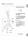
18.1AXT
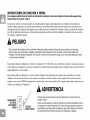
Read the ELLIPTICAL GUIDE before using this OWNER'S MANUAL.
Lire le GUIDE D'UTILISATION DE UEXERCISEUR ELLIPTIQUE avant de se servir du present MANUEL DU PROPRIE_TAIRE.
Lea la GUiA DEL USUARIO DE LA MAQUINA ELiPTICA antes de usar este MANUAL DEL PROPIETARIO.

3 ENGLISH
44 FRANQAIS
86 ESPANOL


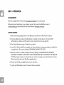
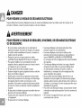
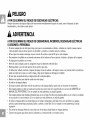
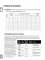
DANGER
TO REDUCE THE RISK OF ELECTRICAL SHOCK:
Always unplug the elliptical from the electrical outlet immediately after using, before cleaning, performing maintenance and putting on or taking
off parts.
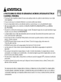
,WARNING
TO REDUCE THE RISK OF BURNS, FIRE, ELECTRICAL SHOCK OR INJURY TO PERSONS:
• If you experience any kind of pain, including but not limited to chest pains, nausea, dizziness, or shortness of breath, stop
exercising immediately and consult your physician before continuing.
• When exercising, always maintain a comfortable pace. Do not sprint above 80 RPMs on this machine.
• To maintain balance, it is recommended to keep a grip on the handlebars while exercising, mounting or dismounting the machine.
• Do not turn pedal arms by hand.
• Make sure handlebars are secure before each use.
• Keep the topside of the foot support clean and dry.
• Care should be taken when mounting or dismounting the equipment. Before mounting or dismounting, move the pedal on the
mounting or dismounting side to its lowest position and bring the machine to a complete stop.
• Do not wear clothes that might catch on any part of the elliptical.
• Always wear athletic shoes while using this equipment.
• Do not jump on the elliptical.
• At no time should more than one person be on the elliptical while in operation.
• This elliptical should not be used by persons weighing more than the specified user capacity in the OWNER'S MANUAL
WARRANTY SECTION. Failure to comply will void the warranty.
• This elliptical is intended for in-home use only. Do not use this elliptical in any commercial, rental, school or institutional setting.
Failure to comply will void the warranty.
• Do not use elliptical in any location that is not temperature controlled, such as but not limited to garages, porches, pool rooms,
bathrooms, car ports or outdoors. Failure to comply will void the warranty.
• To prevent electrical shock, never drop or insert any object into any opening.
• Connect this exercise product to a properly grounded outlet only.

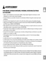
WARNING
TO REDUCE THE RISK OF BURNS, FIRE, ELECTRICAL SHOCK OR INJURY TO PERSONS:
• Keep power cord away from heated surfaces. Do not carry this unit by its supply cord or use the cord as a handle.
• Do not use other attachments that are not recommended by the manufacturer. Attachments may cause injury.
• Do not operate where aerosol (spray) products are being used or when oxygen is being administered.
• Use the elliptical only as described in the elliptical guide and owner's manual.
• Disconnect all power before servicing or moving the equipment. To clean, wipe surfaces down with soap and slightly damp cloth
only; never use solvents. (See MAINTENANCE)
• The elliptical should never be left unattended when plugged in. Unplug from outlet when not in use, and before putting on or
taking off parts.
• Do not operate under blanket or pillow. Excessive heating can occur and cause fire, electric shock, or injury to persons.
• At NO time should pets or children under the age of 13 be closer to the elliptical than 10 feet.
• At NO time should children under the age of 13 use the elliptical.
• Children over the age of 13 or disabled persons should not use the elliptical without adult supervision.
• Never operate the elliptical if it has a damaged cord or plug, if it is not working properly, if it has been dropped or damaged, or
immersed in water. Return the elliptical to a service center for examination and repair.
• To disconnect, turn all controls to the off position, then remove plug from outlet.
• Do not remove the console covers unless instructed by Customer Tech Support. Service should only be done by an authorized
service technician
It is essential that your elliptical is used only indoors, in a climate controlled room. If your elliptica! has been exposed to colder
temperatures or high moisture climates, it is strongly recommended that the elliptical is warmed UP to roo m temperature before ....
first time usel Fai!ure to do so may cause premature e!ectronic fai!urel

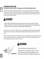
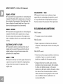
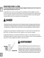
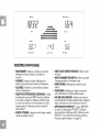
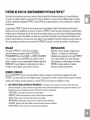
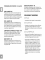
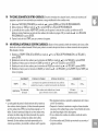
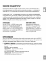
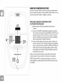
GROUNDING INSTRUCTIONS
If your elliptical has power incline with a 3-prong plug, you must follow these grounding instructions.
This product must be grounded. If a elliptical should malfunction or break down, grounding provides a path of least resistance
for electrical current to reduce the risk of electrical shock. This product is equipped with a cord having an equipment-grounding
conductor and a grounding plug. The plug must be plugged into an appropriate outlet that is properly installed and grounded in
accordance with local codes and ordinances.
DANGER
ImPr0Per c0nnection Of the equipment_gr0unding Conduct °r Can result in a ris k of e!ectric sh0ckl check Wit h a qualified
electricia n Or serviceman if you ar e in doubt as to whether the product is Properly grounded. Donot modify the plug provided .......
with the product. If it wi!l not fit the outlet, have a proper outlet installed by a qualified electrician,
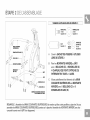
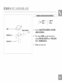
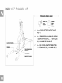
This product is for use on a nominal 110-120 Volt circuit and has a grounding plug that looks like the plug in the illustration. Make
sure that the product is connected to an outlet having the same configuration as the plug. No adapter should be used with this
product.
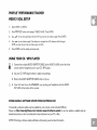
This product must be used on a dedicated circuit. To determine if you are on a dedicated circuit, shut off the power to that circuit and
observe if any other devices lose power. If so, move devices to a different circuit. Note: There are usually multiple outlets on one
circuit. This elliptical should be used with a minimum 15-amp circuit.
3-POLE
GROUNDED
OUTLET
_dDING PIN
WARNING
ConneCt this exercise pi0duct tO a prOPerly grounded Outlet 0nlyl
Never 0Perate Pr0duct with a damaged €0id or p!ug even if it is W0rking
properly. Never 0Perate any PrOduct if it appears damaged, or has been
immersed in waterl Contact customer Tech SupPOrt for replacement Or repair,

7

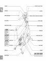
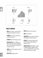
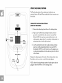
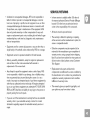
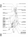
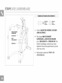
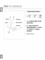
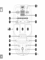
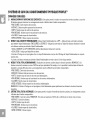
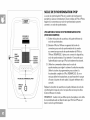
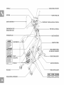
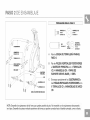
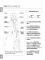
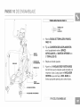
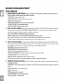
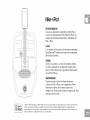
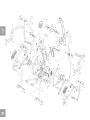
CONSOLE IPOD/MP3 PLAYER POCKET
SPEAKERS
UPPER HANDLEBAR
PULSE GRIPS
WATER BOTTLE HOLDER
_WARNING
CONSULT_PH¥_ICI_NP,IORTOU_ING_N¥
EXERCISEEQUIPMENT_SSIBlU_OF
SERIOUSINJU,¥IfEQUIPM_ISUSED
IMPROPERL_RE_DINSTRUC_ONM_NU_L
BEFO,EUSINGKEEPCHILD,ENOFFEND
_¥ roOMTHISEQUIPM_NTFOR
CONSUME,USEONLY
_,AVERTISSEMENT
_ONSU_TERUNM_OECIN_W_0U_LISE,
TOU_E_U_EMEN__E×E,C_CETOU_
U_US_T_ON_N_ORREBTEPE_OCC_ON_R
L_PP_,E_L_LU_EOUCUE,T_ULEMENT
'_ADVERTENCIA
E_U__U__NCOR,ECT_,Er__EREL
_EL®NSUM_O,
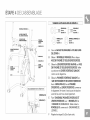
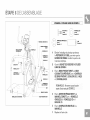
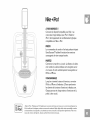
TOP HAND
SWING ARM --
FOOT PADS --
BASE RAIL
REAR UPRIGHT
USB PORT
CONSOLE CONTROLS AND DISPLAY WINDOWS
CONSOLE MAST
LOWER HANDLEBAR
PEDALARM
POWER CORD SOCKET
STABILIZERTUBE
MAIN FRAME
LINK ARM
P_ED_LO_NDECEdERE_ON

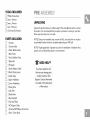
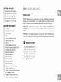
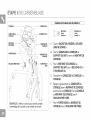
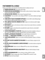
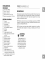
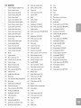
TOOLS INCLUDED:
[] Phillips Screwdriver
[] 6mm L Wrench
[] 5mm L Wrench
[] 5mm T Wrench
[] 13/1 5mm Flat Wrench
PARTS INCLUDED:
[] 1 Console
[] 1 Console Mast
[] 1 Water Bottle Holder
[] 1 Main Frame
[] 1 Front Stabilizer Tube
[] 1 Base Rail
[] 2 Footpads
[] 1 Audio Adaptor Cable
[] 3 iPod® Dock Inserts
[] 2 Crank Caps
[] 2 Upper Hadlebars
[] 2 Lower Handlebars
[] 2 Swing Arms
[] 2 Link Arms
[] 2 Pedal Arms
[] 2 Rear Uprights
[] 2 Top Hand Rails
[] 1 AC Adaptor Cable
[] 1 Universal MP3 Player Dock Insert
[] 1 Polar :_Chest Strap
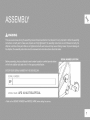
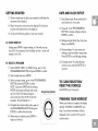
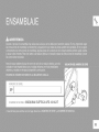
PRE ASSEMBLY
UNPACKING
Unpack the product where you will be using it. Place the elliptical carton on a level
flat surface. It is recommended that you place a protective covering on your floor.
Never open box when it is on its side.
NOTE: During each assembly step, ensure that ALL nuts and bolts are in place
and partially threaded in before completely tightening any ONE bolt.
NOTE: A light application of grease may aid in the installation of hardware. Any
grease, such as lithium bike grease is recommended.
_' NEED HELP?
If you hav e questions or if
there are any missing part s,
contact Customer Tech
support, Contact information
is located on the back panel
Of this manual.

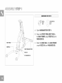
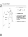
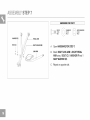
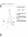
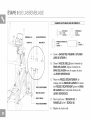
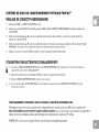
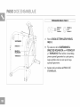
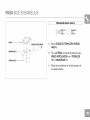
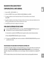
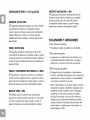
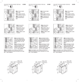
ASSEMBLY STEP 1
MAiN FRAME
FRONT STABILIZER TUBE
_ BOLTS (A)
\ FLAT WASHERS (B)
HARDWARE FOR STEP 1: ]
_ BOLT(A) _> FLATWASHER(B)
20 mm 20 mm
Qty: 8 Qty: 8
A Open HARDWARE FOR STEP 1.
B Attach the FRONT STABILIZER TUBE to
the MAIN FRAM E using 4 BOLTS (A) and 4
WASHERS (B).
C Attach the BASE RAIL to the MAIN FRAME
using 4 BOLTS (A) and 4 WASHERS (B).

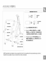
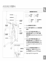
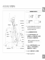
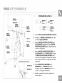
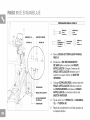
ASSEMBLY STEP 2
TOP HANDRAIL
ARC WASHERS (E) _ / /
AXLE
j ........ WASHERS (D)
l (C)
BASE RAIL BRACKET CAPS
HARDWARE FOR STEP 2: ]
BOLT (C) WASHER (D)
16 mm 25 mm
Qty: 12 Qty: 4
__ ARC WASHER (E)
AXLE 17 mm
Qty: 2 SIDE Qty: 8
VIEW
A Open HARDWARE FOR STEP 2.
B Attach the REAR UPRIGHTS to the BASE
FRAME using 4 BOLTS (C), 4 WASHERS (D),
4 BASE RAIL BRACKET CAPS and 2 AXLES.
C
Partially thread the TOP HAN DRAI LS to the
REAR UPRIGHTS using 8 BOLTS (C) and 8
ARC WASHERS (E).
NOTE:Assemble the top handrails So they are parallel to the floorl Do not assemble With the top handrail resting on the floor.
Assemble the rear uprights so they curve toward the main frame as illustrated.

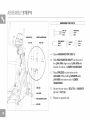
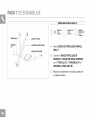
ASSEMBLY STEP 3
TOP HANDRAIL
BOLTS (F)
f
INCLINE
I
HARDWARE FOR STEP 3: ]
(__ BOLT (F) O NUT (G)
25 mm 8 mm
Qty: 4 Qty: 4
A
B
Open HARDWARE FOR STEP 3.
Attach each TOP HANDRAIL to the INCLINE
ARM using 4 BOLTS (F) and 4 NUTS (G). To
make assembly easier, lightly tighten all four
bolts to begin, then tighten firmly after all bolts
have been started.
C Tighten all hardware from ASSEMBLY STEP 2.

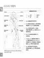
ASSEMBLY STEP 4
6%
//
ZZSN
\ REAR MAST COVE_-- / f
RIGHT UPPER
HANDLEBAR
WASHER(I)
/ /
i
LEFT LOWER
HANDLEBAR /
BOLT(C)
_ BOLTS (H)
i i RIGHT LOWER
HANDLEBAR
HARDWARE FOR STEP 4: ]
__ OLT (H)
20 mm
Qty: 8
BOLT (C)
16 mm
Qty: 2
WASHER (I) WAVY WASHER (J)
34 mm 23 mm
Qty: 2 Qty: 2
A Open HARDWARE FOR STEP 4.
B Slide 1 WAVY WASHER (J) onto each HANDLEBAR
SHAFT.
G Slide the LEFT LOWER HANDLEBAR onto the
HANDLEBAR SHAFT. Be sure the LEFT LOWER
HANDLEBAR ispositioned the same as shown in the
diagram.
D Slide the LEFT UPPER HANDLEBAR onto the
HANDLEBAR SHAFT. Using 4 BOLTS (H) connect
the UPPER AND LOWER HANDLEBARS as shown
inthe diagram. Do not tighten any bolts untilall 4 are
started.
E Secure the HANDLEBAR ASSEMBLY using 1
WASHER (I) and 1 BOLT (C). NOTE: be sure to
attach WASHER (I) as shown inSTEP E diagram.
F Repeat steps B-E on the opposite side.

ASSEMBLY STEP 5
CONSOLE
CONSOLECABLES_
/
PRE-ATTACH ED --
BOLTS /
//
/ /
WATER BOTTLE / /
HOLDER
i
WASHER (L)
/
PRE-ATTACH ED _ FRAME
BOLTS _ BRACKET
NOTE: Be careful not to pinch any wires while attaching the
console mast or console,
HARDWARE FOR STEP 5: ]
BOLT (C) fF_\ WASHER (L)
16 mm _ 18 mm
Qty: 4 Qty: 4
A Open HARDWARE FOR STEP 5.
B Run CONSOLE CABLES from MAIN FRAME
BRACKET through the CONSOLE MAST.
C Attach CONSOLE MAST to the MAIN
FRAME BRACKET using 4 BOLTS (C) and 4
WASHERS (L).
Attach the CONSOLE CABLES to the
CONSOLE.
Carefully tuck the CONSOLE CABLES into
the CONSOLE MAST before attaching the
CONSOLE. Attach CONSOLE to CONSOLE
MAST using 4 PRE-ATTACHED BOLTS.
Attach WATER BOTTLE HOLDER to
CONSOLE MAST using 2 PRE-ATTACHED
BOLTS.

ASSEMBLY STEP 8
FOOTPAD )
" _i_:_,>Ji UNKARM
HARDWARE FOR STEP 6: ]
BOLT (K)
12 mm
Qty: 8
WASHER (L)
18 mm
Qty: 8
A
B
Open HARDWARE FOR STEP 6.
Attach each FOOTPAD to the footpad support
on each LINK ARM using 4 BOLTS (K) and 4
WASHERS (L).
C Repeat on opposite side.

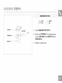
ASSEMBLY STEP "7
WASHER (P)
PEDAL ARM
HARDWARE FOR STEP 7: ]
©-
BOLT(C) WASHER (P) I _ WAVY WASHER (M)
16 mm 38 mm 34 mm
Qty: 2 Qty: 2 Qty: 2
BOLT(c)
WAVY WASHER (M)
LINKARM
A Open HARDWARE FOR STEP 7.
B Attach RIGHT LINK ARM to RIGHT PEDAL
ARM using 1 BOLT (C), 1 WASHER (P) and 1
WAVY WASHER (M).
C Repeat on opposite side.

ASSEMBLY STEP 8
TOP HANDRAIL
/
/
/
WAVY WASHER (J)
RIGHT PEDAL ARM
WASHER (D)
CRANK CAP .....
BOLT (C)
,/ WASHER (D)
/' //
/ /' BOLT (C)
/I...................SWING CAP
//
! .............................................................AXLE
LINK ARM
HARDWARE FOR STEP 8: ]
BOLT (C) WASHER (D)
16 mm 25 mm
Qty: 6 Qty: 6
WAVY WASHER (J) AXLE
29 mm
Qty: 2 Qty: 2
A
B
C
Lay waste packaging plastic over the base rail.
This will prevent the pedal arm assembly from
scratching the elliptical's paint.
Open HARDWARE FOR STEP 8.
Attach RIGHT SWING ARM to TOP
HANDRAIL using 2 SWING CAPS, 2 BOLTS
(C), 2 AXLES and 2 WASHERS (D).
NOTE: Leave bo!ts !00Se unti! YOUhave
finished STEP D.
Attach the RIGHT PEDAL ARM to the right
CRANK using 1 WAVY WASHER (J), 1
WASHER (D) and 1 BOLT (C).
E Attach the CRAN K CAP to the CRAN K.
F Repeat on opposite side.

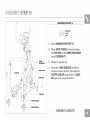
ASSEMBLY STEP 9
//
//
i i
WASHER LOWER HANDLEBAR
BOLT (N)
iJ
SPACER
LINK ARM
ROD BEARING SHAFT
SPACER
HARDWARE FOR STEP 9: ]
BOLT (N)
45 mm
Qty: 2
WASHER (L)
18 mm
Qty: 2
ROD BEARING SPACER _ NUT (G)
SHAFT 8 mm
Qty: 2 Qty: 4
Qty: 2
A Open HARDWARE FOR STEP 9.
B Slide ROD BEARING SHAFT into the end of
the LINKARM. Align end of LINKARM with
bracket on bottom of LOWER HAN DLEBAR.
C Place SPACERS on both sides of the
LINK ARM. While holding SPACERS slide
LINK ARM into bottom end of LOWER
HANDLEBAR.
Secure the joint using 1 BOLT (N), 1 WASHER
(L) and 1 NUT (G).
E Repeat on opposite side.

ASSEMBLY STEP lO
//
//
LEVELERS
LOWER
HANDLEBAR
COVERS
SCREWS (0)
LINK ARM
HARDWARE FOR STEP 10:1
SCREW (O)
12 mm
qty: 6
A Open HARDWARE FOR STEP 10.
B Attach JOINT COVERS to the joint between
the LINK ARM and the LOWER HANDLEBAR
using 3 SCREWS (O).
C Repeat on opposite side.
D Adjust the 2 REAR LEVELERS so that the
machine is level on the floor. Then adjust the
CENTER LEVELER located under the BASE
RAIL just so it is snug with the floor.

La page est en cours de chargement...
La page est en cours de chargement...
La page est en cours de chargement...
La page est en cours de chargement...
La page est en cours de chargement...
La page est en cours de chargement...
La page est en cours de chargement...
La page est en cours de chargement...
La page est en cours de chargement...
La page est en cours de chargement...
La page est en cours de chargement...
La page est en cours de chargement...
La page est en cours de chargement...
La page est en cours de chargement...
La page est en cours de chargement...
La page est en cours de chargement...
La page est en cours de chargement...
La page est en cours de chargement...
La page est en cours de chargement...
La page est en cours de chargement...
La page est en cours de chargement...
La page est en cours de chargement...
La page est en cours de chargement...
La page est en cours de chargement...
La page est en cours de chargement...
La page est en cours de chargement...
La page est en cours de chargement...
La page est en cours de chargement...
La page est en cours de chargement...
La page est en cours de chargement...
La page est en cours de chargement...
La page est en cours de chargement...
La page est en cours de chargement...
La page est en cours de chargement...
La page est en cours de chargement...
La page est en cours de chargement...
La page est en cours de chargement...
La page est en cours de chargement...
La page est en cours de chargement...
La page est en cours de chargement...
La page est en cours de chargement...
La page est en cours de chargement...
La page est en cours de chargement...
La page est en cours de chargement...
La page est en cours de chargement...
La page est en cours de chargement...
La page est en cours de chargement...
La page est en cours de chargement...
La page est en cours de chargement...
La page est en cours de chargement...
La page est en cours de chargement...
La page est en cours de chargement...
La page est en cours de chargement...
La page est en cours de chargement...
La page est en cours de chargement...
La page est en cours de chargement...
La page est en cours de chargement...
La page est en cours de chargement...
La page est en cours de chargement...
La page est en cours de chargement...
La page est en cours de chargement...
La page est en cours de chargement...
La page est en cours de chargement...
La page est en cours de chargement...
La page est en cours de chargement...
La page est en cours de chargement...
La page est en cours de chargement...
La page est en cours de chargement...
La page est en cours de chargement...
La page est en cours de chargement...
La page est en cours de chargement...
La page est en cours de chargement...
La page est en cours de chargement...
La page est en cours de chargement...
La page est en cours de chargement...
La page est en cours de chargement...
La page est en cours de chargement...
La page est en cours de chargement...
La page est en cours de chargement...
La page est en cours de chargement...
La page est en cours de chargement...
La page est en cours de chargement...
La page est en cours de chargement...
La page est en cours de chargement...
La page est en cours de chargement...
La page est en cours de chargement...
La page est en cours de chargement...
La page est en cours de chargement...
La page est en cours de chargement...
La page est en cours de chargement...
La page est en cours de chargement...
La page est en cours de chargement...
La page est en cours de chargement...
La page est en cours de chargement...
La page est en cours de chargement...
La page est en cours de chargement...
La page est en cours de chargement...
La page est en cours de chargement...
La page est en cours de chargement...
La page est en cours de chargement...
La page est en cours de chargement...
La page est en cours de chargement...
La page est en cours de chargement...
La page est en cours de chargement...
La page est en cours de chargement...
La page est en cours de chargement...
La page est en cours de chargement...
La page est en cours de chargement...
La page est en cours de chargement...
La page est en cours de chargement...
La page est en cours de chargement...
La page est en cours de chargement...
La page est en cours de chargement...
La page est en cours de chargement...
La page est en cours de chargement...
La page est en cours de chargement...
-
 1
1
-
 2
2
-
 3
3
-
 4
4
-
 5
5
-
 6
6
-
 7
7
-
 8
8
-
 9
9
-
 10
10
-
 11
11
-
 12
12
-
 13
13
-
 14
14
-
 15
15
-
 16
16
-
 17
17
-
 18
18
-
 19
19
-
 20
20
-
 21
21
-
 22
22
-
 23
23
-
 24
24
-
 25
25
-
 26
26
-
 27
27
-
 28
28
-
 29
29
-
 30
30
-
 31
31
-
 32
32
-
 33
33
-
 34
34
-
 35
35
-
 36
36
-
 37
37
-
 38
38
-
 39
39
-
 40
40
-
 41
41
-
 42
42
-
 43
43
-
 44
44
-
 45
45
-
 46
46
-
 47
47
-
 48
48
-
 49
49
-
 50
50
-
 51
51
-
 52
52
-
 53
53
-
 54
54
-
 55
55
-
 56
56
-
 57
57
-
 58
58
-
 59
59
-
 60
60
-
 61
61
-
 62
62
-
 63
63
-
 64
64
-
 65
65
-
 66
66
-
 67
67
-
 68
68
-
 69
69
-
 70
70
-
 71
71
-
 72
72
-
 73
73
-
 74
74
-
 75
75
-
 76
76
-
 77
77
-
 78
78
-
 79
79
-
 80
80
-
 81
81
-
 82
82
-
 83
83
-
 84
84
-
 85
85
-
 86
86
-
 87
87
-
 88
88
-
 89
89
-
 90
90
-
 91
91
-
 92
92
-
 93
93
-
 94
94
-
 95
95
-
 96
96
-
 97
97
-
 98
98
-
 99
99
-
 100
100
-
 101
101
-
 102
102
-
 103
103
-
 104
104
-
 105
105
-
 106
106
-
 107
107
-
 108
108
-
 109
109
-
 110
110
-
 111
111
-
 112
112
-
 113
113
-
 114
114
-
 115
115
-
 116
116
-
 117
117
-
 118
118
-
 119
119
-
 120
120
-
 121
121
-
 122
122
-
 123
123
-
 124
124
-
 125
125
-
 126
126
-
 127
127
-
 128
128
-
 129
129
-
 130
130
-
 131
131
-
 132
132
-
 133
133
-
 134
134
-
 135
135
-
 136
136


dans d''autres langues
Documents connexes
Autres documents
-
 T'nB IPH5SBUMPBK Fiche technique
-
Horizon Fitness CE9.2 Manuel utilisateur
-
-
-
Apple J034-4945-A Manuel utilisateur
-
-
 Prime-Line N 7079 Mode d'emploi
-
 Mode FuelBand Mode d'emploi
-
Nike Amp+ Manuel utilisateur


