Bercomac C151 61576 0 _ C151 61577 0 Manuel utilisateur
- Catégorie
- Souffleuses à neige
- Taper
- Manuel utilisateur

1
OWNER’S
MANUAL
MODEL NO.
C 151 61576 0
C 151 61577 0
Caution:
Read and Follow
All Safety Rules
and Instructions
Before Operating
This Equipment
44" AND 48" NORTHEAST TWO
STAGE SNOWBLOWER FOR
CRAFTSMAN TRACTORS
·Assembly
·Operation
·Maintenance
·Repair Parts
Sears Canada, Inc., Toronto, Ontario M5B 2B8
104158 F-07

2
LIMITED ONE (1) YEAR WARRANTY ON CRAFTSMAN
TRACTOR ATTACHMENTS "SNOWBLOWER"
For one (1) year from date of purchase, Sears Canada Inc. will repair or replace free of charge at Sears option any
parts which are defective as a result of defective material or faulty workmanship.
COMMERCIAL OR RENTAL USE:
Warranty on Tractor Attachments "Snowblower" used for commercial or rental purposes is limited to 90 days.
This warranty does NOT cover:
* Wear items, such as shear pins and shear bolts, belts
* Repairs due to customer abuse or neglect
* Pre-delivery set-up
* In Home service
Warranty service is available by returning the Craftsman Tractor Attachment to the nearest Sears Service Centre /
Department in Canada. This warranty applies only while this product is in use in Canada.
This warranty is in addition to any statutory warranty and does not exclude or limit legal rights you may have but shall
run concurrently with applicable provincial legislation. Furthermore, some provinces do NOT allow limitation on how
long an implied warranty will last so the above limitations may not apply to you.
SEARS CANADA INC., TORONTO, ONTARIO, M5B 2B8
FOR SERVICE PLEASE CALL
SEARS HOME CENTRAL
1-800-4-MY-HOME®
WARRANTY

1
INTRODUCTION ...................................................................................................................................... 2
SAFETY PRECAUTIONS ......................................................................................................................... 3
SAFETY DECALS ..................................................................................................................................... 5
ASSEMBLY
Step 1: Tractor Preparation .......................................................................................................... 6
Step 2: Subframe Installation ....................................................................................................... 7
Step 3: Drive Mechanism Preparation ......................................................................................... 11
Step 4: Drive Mechanism Installation ........................................................................................... 13
Step 5: Snowblower Preparation ................................................................................................. 14
Step 6: Snowblower Installation ................................................................................................... 15
OPERATION
Snowblower Operation ................................................................................................................. 17
Controls ........................................................................................................................................ 17
Snow Removal ............................................................................................................................. 17
MAINTENANCE
Maintenance ................................................................................................................................ 18
Adjustments ................................................................................................................................. 18
Lubrication ................................................................................................................................... 18
Cutting Edge Maintenance ........................................................................................................... 18
Auger and Fan Shear Bolt Replacement ..................................................................................... 18
End of Season Storage ................................................................................................................ 18
Belt Installation, Adjustment and Replacement ........................................................................... 19
DISMOUNTING
Snowblower Dismounting ............................................................................................................ 22
Drive Mechanism Dismounting .................................................................................................... 20
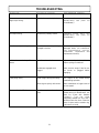
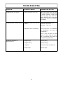
TROUBLESHOOTING .............................................................................................................................. 21
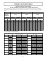
TORQUE SPECIFICATION TABLE .......................................................................................................... 23
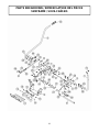
PARTS BREAKDOWN & LISTS
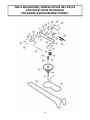
Drive Mechanism ......................................................................................................................... 24
Subframe ..................................................................................................................................... 26
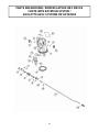
Chute with Rotation System ......................................................................................................... 29
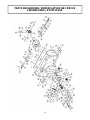
Snowblower ................................................................................................................................. 31
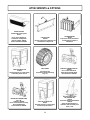
OPTIONS & ATTACHMENTS ............................................................................................... 34
CONSUMER INFORMATION .............................................................................................................................. 35
TABLE OF CONTENTS
Page

2
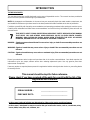
INTRODUCTION
TO THE PURCHASER
This new attachment was carefully designed to give years of dependable service. This manual has been provided to
assist in the safe operation and servicing of your attachment.
NOTE: All photographs and illustrations in the manual may not necessarily depict the actual models or attachment, but
are intended for reference only and are based on the latest product information available at the time of publication.
Familiarize yourself fully with the safety recommendations and operating procedures before putting the machine to use.
Carefully read, understand and follow these recommendations and insist that they be followed by those who will use
this attachment.
THIS SAFETY ALERT SYMBOL IDENTIFIES AN IMPORTANT SAFETY MESSAGE IN THIS MANUAL
THAT HELPS YOU AND OTHERS AVOID PERSONAL INJURY OR EVEN DEATH. DANGER,
WARNING, AND CAUTION ARE SIGNAL WORDS USED TO IDENTIFY THE LEVEL OF HAZARD.
HOWEVER, REGARDLESS OF THE HAZARD, BE EXTREMELY CAREFUL.
DANGER: Signals an extreme hazard that will cause serious injury or death if recommended precautions are
not followed.
WARNING: Signals a hazard that may cause serious injury or death if the recommended precautions are not
followed.
CAUTION: Signals a hazard that may cause minor or moderate injury if the recommended precautions are not
followed.
Record your attachment serial number and purchase date in the section reserved below. Your dealer requires this
information to give you prompt, efficient service when ordering replacement parts. Use only genuine parts when
replacements are required.
If warranty repairs are required please present this registration booklet and original sales invoice to your selling dealer
for warranty service.
This manual should be kept for future reference.
Please check if you have received all the parts for your kit with the list of the
bag and the list of the box.
7
SERIAL NUMBER : ___________________________
PURCHASE DATE : ___________________________
In this manual, right and left sides are determined by sitting on the tractor seat facing forward.
In this manual, "attachment" means accessories that you install on the tractor, such as, snowblower, rotary
broom, blade, rotary tiller, cab, subframe, etc...

3
SAFETY PRECAUTIONS
Careful operation is your best insurance against an accident. Read this section carefully before operating the tractor
and snowblower. This snowblower is capable of amputating hands and feet and throwing objects. Failure to observe
the following safety instructions could result in serious injury. All operators, no matter how experienced they may be,
should read this and other manuals related to the tractor and snowblower before operating. It is the owner's legal
obligation to instruct all operators in safe operation of the snowblower.
TRAINING
This symbol, "Safety Alert Symbol", is used
throughout this manual and on the snowblower’s
safety labels to warn of the possibility of serious
injuries. Please take special care in reading and
understanding the safety precautions before
operating the snowblower or the tractor.
1. Read this owner's manual carefully. Be thoroughly
familiar with the controls and proper use of the
tractor and snowblower. Know how to stop the unit
and disengage the controls quickly.
2. Never allow children to operate snowblower nor the
tractor. Never allow adults to operate snowblower
nor the tractor without proper instructions.
3. No one should operate the tractor nor the
snowblower while intoxicated or while taking
medication that impairs the senses or reactions.
4. Keep the area of operation clear of all persons,
particularly small children and pets.
PREPARATION
1. Thoroughly inspect the area where the snowblower
is to be used and remove door mats, all foreign
objects and the like.
2. Disengage all clutches and shift into neutral before
starting engine.
3. Do not operate the snowblower without wearing
adequate winter outer garments. Avoid loose fitting
clothing that can get caught in moving parts. Wear
footwear that will improve footing on slippery
surfaces.
4. Handle fuel with care, it is highly flammable.
a) Use approved fuel container.
b) Never add fuel to a running engine or hot
engine.
c) Fill fuel tank outdoors with extreme care. Never
fill fuel tank indoors.
d) Never fill containers inside a vehicle, or on a
truck or a trailer bed with a plastic liner. Always
place containers on the ground, away from your
vehicle, before filling.
7
e) When practical, remove gas-powered equipment
from the truck or trailer and refuel it on the
ground. If this is not possible, then refuel such
equipment on a trailer with a portable container,
rather than from a gasoline dispenser nozzle.
f) Keep the nozzle in contact with the rim of the
fuel tank or container opening at all times, until
refuelling is complete. Do not use a nozzle lock-
open device.
g) Replace fuel cap securely and wipe up spilled
fuel.
h) If fuel is spilled on clothing, change clothing
immediately.
5. Adjust the height of the snowblower to clear gravel
or crushed rock surface. This is done by adjusting
the skid shoes.
6. Never attempt to make any adjustments while the
engine (motor) is running (except when specifically
recommended by manufacturer).
7. Let engine (motor), tractor and snowblower adjust
to outdoor temperatures before starting to clear
snow.
8. Always wear safety glasses or eye shields during
operation or while performing an adjustment or
repair to protect eyes from foreign objects that may
be thrown from the snowblower.
9. Never modify the snowblower or any part
without the written consent from the
manufacturer.
OPERATION
1. Do not put hands or feet near or under rotating
parts. Keep clear of the discharge opening at all
times.
2. Exercise extreme caution when operating on or
crossing gravel drives, walks, or roads. Stay alert
for hidden hazards or traffic.
3. After striking a foreign object, stop the engine
(motor), disconnect the wire from the spark plug(s)
and keep wire away to prevent accidental starting.
Thoroughly inspect the snowblower for any damage
and repair damage before restarting and operating
the snowblower.

4
SAFETY PRECAUTIONS
4. If the unit should start to vibrate abnormally, stop
the engine (motor) and check immediately for the
cause. Vibration is generally a warning of trouble.
5. Stop the engine (motor) whenever you leave the
operating position, before unclogging the impeller/
collector housing or discharge chute, and when
making repairs, adjustments or inspections.
6. Take all possible precautions when leaving the
machine unattended. Disengage the power take-off,
lower the attachment, set the parking brake, shut
the engine off and remove the key.
7. When cleaning, unclogging, repairing or inspecting
the snowblower & tractor, make certain the
collector/impeller and all moving parts have
stopped. Disconnect wire from the spark plug(s)
and keep wire away to prevent accidental starting.
8. Do not run the engine indoors, except when
starting the engine and for transporting the
snowblower in or out of the building. Do not
operate or let motor run in a storage area without
ventilation because gas contains carbon monoxide
which is odourless, colorless and can cause death.
9. Do not clear snow across the face of slopes; go up
and down. Exercise extreme caution when
operating on slopes. Do not attempt to clear steep
slopes.
10. Never operate the snowblower without proper
guards, plates, or other safety protective devices in
place.
11. Never direct discharge at bystanders or operate
the snowblower near glass enclosures,
automobiles, window wells, drop-offs, and the like
without proper adjustment of the snow discharge
angle. Never allow anyone including children and
pets in the clearance area.
12. Do not overload the machine capacity by
attempting to clear snow at too fast a rate. Let the
snowblower ingest snow at its own rate.
13. Never operate the snowblower at high transport
speeds on slippery surfaces. Look behind and use
care when backing.
14. Do not carry passengers.
15. Disengage power to the collector /impeller to stop
all rotating parts when the snowblower is
transported or not in use.
MAINTENANCE AND STORAGE
1. Check shear bolts, engine mounting bolts, and
other bolts at frequent intervals for proper tightness
to be sure the snowblower is in safe working
condition.
2. Never store the machine with fuel in the fuel tank
inside a building where ignition sources are
present such as hot water and space heaters,
clothes dryers, and the like. Allow the engine to
cool before storing in any enclosure.
3. Always refer to the owner’s manual when you store
the snowblower for an extended period.
4. Maintain or replace safety and instruction labels,
as necessary.
5. Run the snowblower a few minutes after throwing
snow to prevent freeze-up of the rotating parts
such as collector/impeller.
WHENEVER YOU SEE THIS SYMBOL
7
IT MEANS:
WARNING!
BECOME ALERT !
YOUR SAFETY IS INVOLVED!
16. Use only accessories approved by the
manufacturer of the snowblower (such as wheel
chains, counterweights, cabs). You must use 100
lbs. of rear counterweight for better traction and a
greater stability at all times when using a
snowblower that is installed on the front of a
tractor.
17. Never operate the snowblower without good
visibility or light.
CLEARING A CLOGGED DISCHARGE CHUTE:
Hand contact with the rotating impeller inside the
discharge chute is the most common cause of injury
associated with snowblowers. Never use your hand to
clean out the discharge chute.
To clear the chute:
1. Lower snowblower to the ground and set parking
brake.
2. SHUT THE ENGINE OFF & REMOVE KEY!
3. Wait 10 seconds to be sure the all moving parts
such as the impeller blades have stopped moving.
4. Disconnect wire from the spark plug(s) and keep
wire away to prevent accidental starting.
5. Always use a clean-out tool of at least 36” in length,
NOT YOUR HANDS.

5
SAFETY DECALS
REPLACE IF DECALS ARE DAMAGED
SEE PARTS BREAKDOWN FOR DECAL LOCATION
Decal # 102125 Decal # 102126
Decal # 102127 Decal # 103951
Decal # 102124
Decal # 102128

6
ASSEMBLY
IMPORTANT: TORQUE ALL BOLTS ACCORDING
TO TORQUE SPECIFICATION TABLE (SEE TABLE
OF CONTENTS) WHEN STATED: TIGHTEN
FIRMLY. REFER TO PARTS BREAKDOWN
SECTION FOR PARTS IDENTIFICATION.
NOTE: This subframe was designed to fit various
models of Lawn, Yard or Garden tractors. (See
illustrations to identify your tractor).
This subframe may be used to install different
attachments (see attachments page). Once installed,
it may remain permanently on the tractor. Before
doing any modifications or installations on the tractor,
open the tractor hood, disconnect the headlights and
remove the hood. Disconnect the wire from the spark
plug(s) and keep away from spark plug(s) to prevent
accidental starting.
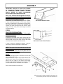
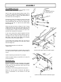
STEP 1
TRACTOR PREPARATION:
IT IS NOT NECESSARY TO REMOVE THE MOWER
DECK AT THIS STEP.
According to the model of the tractor, remove the front
attaching supports if they are bolted to the outside of the
tractor’s frame (one on each side) and the heat shield
(save the bolts to install the new heat shield).
In order to install the subframe’s supports, it may be
necessary to remove certain bolts or certain parts.
NOTE: Take note of the place and how the bolts and
parts were installed in order to reinstall them in the same
manner as before.
If applicable, make sure that the belt guide does not
touch any part when reinstalled.
How to:
Take the right support (item 1) and place it on the right
side of the tractor’s frame.
Align the hole (item 2) on the right support with the hole
(item 3) which is about 2” (according to the model of the
tractor) from the edge of the tractor’s front frame.
Remove all the bolts and parts from the tractor’s frame
that will interfere with the installation of the support.
Do the same operation on the left side.
Align the holes in order to identify and remove the
bolts and/or parts that come into interference
Back end of Garden Tractor
Back end of Lawn & Yard Tractors

7
ASSEMBLY
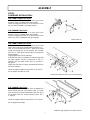
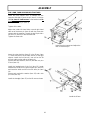
FOR LAWN & YARD TRACTORS:
On the right side install the right support (item 2) and
hold in place with three thread cutting screw 3/8 x 1"
(item 3), one carriage bolt 5/16 x 1 (item 6) the head
inside, one flange nut on the outside, one carriage
bolt 3/8 x 1" (item 4) the head inside, one flange nut
on the outside.
Slightly tighten the screws and bolts.
Slide the shim (item 1) between the tractor frame and
the right support. Secure in place with a 3/8 x 1"
carriage bolt the head inside (item 5) and with a
flange nut.
(Make sure that the shim stays perpendicular with the
top of the support).
Install the square head set screw 5/16 x 1/2" (item 7).
Do not tighten the bolts nor nuts.
FOR GARDEN TRACTORS:
On the right side, install the shim (item 1) between the
tractor frame and the right support (item 2) (make
sure that the shim stays perpendicular with the top of
the support) with four thread cutting screws 3/8 x
1" (item 3).
Install the square head set screw 5/16 x 1/2" (item 4).
Do not tighten the screws.
Install right support on the Lawn & Yard tractors
Install the right support on Garden tractors
Install brace pin
FOR LAWN & YARD TRACTORS:
Install a hex. nut 1/2" (item 1) on each end of the
brace pin (item 2) (halfway down the threads).
Install the longest end (item 2) of the brace pin in the
top nut (item 4) welded on the right support.
FOR GARDEN TRACTORS:
Install a hex. nut 1/2" (item 1) on each end of the
brace pin (item 2) (halfway down the threads).
Install the longest end (item 2) of the brace pin in the
bottom nut (item 3) welded on the right support.
STEP 2
SUBFRAME INSTALLATION:

8
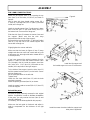
FOR LAWN & YARD TRACTORS:
Install the left support (item 1) by inserting the top
hole (item 3) on the brace pin (item 2) as shown in
figure A.
Hold in place with three thread cutting screws 3/8 x
1" (item 4), a carriage bolt 5/16 x 1" (item 5) (the head
inside) and a flange nut.
Install the handle support (item 7) and secure in place
with a hex bolt 3/8 x 1" (the head inside) (item 8) in
the bottom hole. Secure with a flange nut.
Slide the shim (item 6) between the tractor frame and
the support. (Make sure that the shim stays
perpendicular with the top of the support).
Secure with the last hex bolt 3/8 x 1" (the head inside)
(item 8) in the top hole of the handle support and
secure with a flange nut.
Slightly tighten the screws and bolts.
Make sure that the brace pin (figure A, item 2) stays
straight and does not come into contact with any part
of the tractor (ex: the engine belt when mower deck is
in raised position).
If you have removed the original supports from the
tractor, in order to install the mower brackets (item
12) (included in this kit) inside the support, insert two
hex. bolts 3/8 x 1 1/4" (item 10) (the heads on the
outside) in the top holes of the right support .
To the inside of the support, insert the shim (item 11)
and the mower bracket (item 12) on the bolts. Secure
with two flange nuts.
Do the same operation on the left side.
Tighten firmly.
Install the new heat shield (item 13) with the bolts
previously removed.
Install the plastic grommet (item 14) as shown.
Install the square head set screw 5/16 x 1/2" (item 15)
in the cab support.
Reinstall the parts:
Reinstall the parts previously removed in their original
position. If applicable, in order to facilitate reinstallation
of the parts, you may remove the lever (item 9) and
reinstall it afterwards.
(If necessary, use the bolts supplied for this purpose).
Make sure the belt guide is functional and adjust in
order to compensate for the thickness of the right
support. Install the mower brackets inside the support and
other parts if applicable.
Figure A
ASSEMBLY
Install the left support and
the handle support on Lawn & Yard tractors

9
ASSEMBLY
FOR GARDEN TRACTORS:
Install the left support (item 1) by inserting it on the
brace pin (item 2) as shown in figure A.
Hold in place with two thread cutting screws 3/8 x
1" (item 4). Install and the handle support (item 5)
with a hex bolt 3/8 x 1" (item 6) (the head inside) in
the bottom hole and a flange nut.
Slide the shim (item 3) between the tractor frame and
the left support (item 1) (make sure that the shim
stays perpendicular with the top of the support) with
the last hex bolt 3/8 x 1" (item 6) (the head inside)
and a flange nut.
Make sure that the brace pin (figure A, item 2) stays
straight and does not come into contact with any part
of the tractor (ex: the engine belt when mower deck is
in raised position). If it does, turn the brace pin to use
another hole created for this purpose.
If you have removed the original supports from the
tractor, in order to install the mower brackets (item 9),
(included in this kit) inside the support insert two hex.
bolts 3/8 x 1 1/4" (item 7) (the heads on the outside)
in the bottom holes of the right support.
To the inside of the support, attach the shim (item 8)
and the mower bracket (item 9) on the bolts. Secure
with two flange nuts.
Do the same operation on the left side.
Tighten firmly.
Secure the heat shield with a thread cutting screw 3/8
x 1" (item 10) and a spacer (item 11) on each side as
shown.
Install the plastic grommet (item 12) as shown.
Install the square head set screw 5/16 x 1/2" (item 13)
in the cab support.
Reinstall the parts:
Reinstall the parts previously removed in their original
position. If applicable, in order to facilitate reinstallation
of the parts, you may remove the lever (item 14) and
reinstall it afterwards.
(If necessary, use the bolts supplied for this purpose).
Make sure the belt guide is functional and adjust in
order to compensate for the thickness of the right
support.
Install the left support and the handle support
Figure A
3 possible positions
for the brace pin
Install the mower brackets inside the support

10
FOR LAWN, YARD AND GARDEN TRACTORS:
Turn the front wheels towards the left.
Install the pivot support (item 1) between the two
supports and slide in place the pin (item 2) in the top
hole for Lawn & Yard tractors or the bottom hole for
Garden tractors.
Secure with the hair pin (item 3).
Tighten all the bolts.
Adjust the inside left hand side nut and right hand
side nut of the brace pin (item 4) until they come into
contact with the supports. Secure the brace pin with a
hex nut 1/2" (item 5) on the left hand side.
Tighten the three nuts.
Insert the nylon bushing (item 6) in the lift arm (item
7). Insert the lift arm on the tube (item 8) of the right
support. Install the link (item 9), one end on the lift
arm pin and the other end on the lever pin.
Secure with two washers (item 10) and two hair pins
2.5mm (item 11).
Install the bended part of the link (item 12) (angle
towards the inside) on the pivot support pin (item 13)
and insert the other end of link on the lever pin (item
14).
Secure each end with a washer (item 15) and a hair
pin 3mm (item 16).
Install the handgrip (item 17) on the lift arm as shown.
ASSEMBLY
Install the lift arm
Install the pivot support and adjust the
nuts on the brace pin.
ASSEMBLY

11
VERY IMPORTANT
ADJUST THE LIFT HEIGHT OF THE
ACCESSORIES ON LAWN,YARD AND GARDEN
TRACTORS.
This adjustment is necessary in order to allow the
accessories to follow the contours of the ground
and to avoid damage to the accessories.
The link (item 1) has an adjustment bolt (item 2) to
adjust the height of the accessories:
Compact Snowblower: max. 4" from the ground.
Northeast Snowblower: max. 4" from the ground.
Rotary Broom: 1 1/2" over the swivel wheels.
Utility Blade: no restrictions.
When the adjustment is done tighten the lock nut.
ALSO SEE ACCESSORY INSTALLATION SECTION FOR TIRE
PRESSURE.
NON COMPLIANCE WITH THESE INSTRUCTIONS
MAY DAMAGE THE BELTS AND THE DRIVE
MECHANISM.
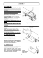
STEP 3
DRIVE MECHANISM PREPARATION:
NOTE: You must remove the mower deck to install
and use the drive mechanism.
Remove the left mower bracket.
Keep these parts for reinstallation of the mower deck.
FOR LAWN &|YARD TRACTORS:
Secure the square supports as shown with two
carriage bolts 3/8 x 3/4" (item 1) the heads inside.
Secure with two flange nuts.
Do the same operation on other side.
Note: Due to the wide variety of tractor models on
the market, these supports can be installed in
different ways. See illustration A or B.
FOR GARDEN TRACTORS:
To install the drive mechanism, you must remove the
two bolts from the footrests (from each side).
Secure the left support (longest support with point
towards the front) and the right support (shortest
support with point towards the front) with the bolts
removed from the footrests. See figure A.
Adjust the lift height of the accessories
ASSEMBLY
Figure A,
Install supports on
Garden tractor
Install supports on Lawn &
Yard tractors

12
ASSEMBLY
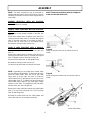
NOTE: This drive mechanism may be mounted on
tractors with two types of clutch mechanisms. See the
following instructions for those that are appropriate for
your tractor.
GARDEN TRACTORS WITH AN ELECTRIC
CLUTCH.
No modifications are needed.
LAWN & YARD TRACTORS WITH AN ELECTRIC
CLUTCH
Remove the spring already installed on the idler arm
(item 1).
Remove the support (item 2) and the shim (item 3) by
removing the two bolts (item 4). Reinstall the support
(item 2) and the shim (item 3) as shown in figure A.
Secure with the bolts (item 4) and tighten firmly.
Reinstall the spring on idler arm (item 1).
LAWN & YARD TRACTORS WITH A MANUAL
CLUTCH ACTIVATED BY A CABLE.
Remove the spring that is hooked to the idler arm
(item 1)
Remove the support (item 2) and the shim (item 3) by
removing the two bolts (item 4). Reinstall the support
(item 2) without the shim as shown in figure B.
Secure with the bolts (item 4) and tighten firmly.
Reinstall the spring on idler arm (item 1).
Cut the tie wrap that holds the cable to the frame.
NOTE: Depending on the mower deck model, there
are two different cable lengths. To determine where to
place the cable holder, hook the end of the cable
spring (item 5) on the idler arm (item 1). Slide the
cable shield (item 6) temporarily into the slot on the
cable holder (item 7). To identify into which holes the
cable holder will be bolted in, you must apply a slight
tension on the cable. This adjustment must be done
with the clutch arm in the off position.
Remove the cable shield and secure the cable holder
(item 7) on the frame using two 1/4 x 3/4" hex bolts
(item 8) and flange nuts.
Reinstall the cable shield into the cable holder and
secure with the hair pin previously removed.
Install cable holder
Figure B
Install the support without shim for manual clutch as
shown.
Figure A
Install the support with shim for electric clutch as
shown
NOTE: The drive mechanism must be straight, to
make sure the belt works well.

13
ASSEMBLY
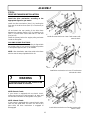
STEP 4
DRIVE MECHANISM INSTALLATION:
Install the drive mechanism according to the
appropriate figure for you tractor.
Install the drive mechanism (item 1) by hooking the
front part of the drive frame (item 2) on the brace pin
(item 3).
Lift and attach the rear portion of the drive frame
between the supports (items 4 & 5) by inserting a pin
(item 7) on each side. Secure with two 2.5 mm hair
pins (item 6).
Install the primary belt on the engine pulley and route
inside the belt guide.
ON LAWN & YARD TRACTORS:
Make sure the drive mechanism pulley is aligned with
the engine pulley. If not, you may change the position
of the square supports (item 5) as needed.
NOTE: After installation, attach the cable to the frame
with the new tie wrap supplied with this kit.
Install drive mechanism on Lawn Yard tractors with
manual clutch.
NOTE:Electric Clutch :
If your tractor is equipped with an electric clutch,
make sure the spring is well inserted in its place and
the belt does not touch the belt guides at any point.
NOTE: Manual Clutch:
If your tractor is equipped with a manual clutch, make
sure the belt guide does not touch the belt at any
point while the drive mechanism is engaged or
disengaged.
7 WARNING 7
TO PREVENT INJURIES DO THIS VERIFICATION
WHEN THE ENGINE IS STOPPED.
Install drive mechanism on Lawn & Yard tractors
with electric clutch.
Install drive mechanism on Garden tractors with
electric clutch.

14
ASSEMBLY
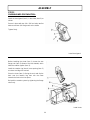
STEP 5
SNOWBLOWER PREPARATION:
Install the hand guard (item 1) in the chute (item 2) as
shown.
Secure in place with two 1/4 x 3/4" hex bolts, two flat
washers and two 1/4’’ flange nuts on the inside.
Tighten firmly.
Install chute
Install hand guard
Before installing the chute (item 1), loosen the two
flange nuts (item 2) (down to the last threads) which
holds the rotation system (item 3).
Install the rotation ring (item 4) over opening (item 5)
as shown and align the notches.
Place the chute (item 1) (facing the rear) and clip the
back over the rotation ring then turn the chute
towards the front to lock into place.
Reinstall the rotation system by tightening the flange
nuts firmly.

15
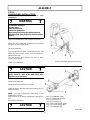
STEP 6
SNOWBLOWER INSTALLATION:
Refer to parts breakdown section for parts
identification.
ASSEMBLY
Remove the belt guard.
Install the belt on the pulleys as shown.
Install the belt on the drive mechanism pulley (item 5)
under the tractor.
NOTE: See belt replacement instructions in the
Maintenance section.
Apply tension on the belt by pulling up the belt tension
arm.
Reinstall the belt guard.
Install belt
Item 1: Snowblower pulley
Item 2: Tractor engine pulley
Item 3: Flat pulley L.H.
Item 4: Flat pulley R.H.
Item 5: Drive mechanism pulley
Item 6: Drive mechanism belt
Item 7: Snowblower belt
7 CAUTION 7
Never use the snowblower without the belt guard.
7 CAUTION 7
The belt tension and lift assist spring arm are
spring loaded & need to be held firmly while
displacing to prevent injury.
7 WARNING 7
TO PREVENT INJURIES:
Stop the motor.
Apply parking brake.
Remove the ignition key.
Disconnect the wire from the spark plug(s) and
keep away from spark plug(s) to prevent accidental
starting.
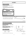
Attach the snowblower to the subframe as shown.
Make sure the snowblower is pushed in until locked
into place by the springs (item 3).
Lift the snowblower.
Turn the tension arm (item 1) towards the back and
install the chain (item 2) on the hook (if subframe is
equipped with one).
Turn the tension arm towards the front to apply
tension on the spring.
Lower the snowblower. Install snowblower and lift assist spring

16
ASSEMBLY
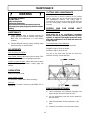
VERIFY SKID SHOE ADJUSTMENT:
LEVEL PAVED SURFACE: Adjust skid shoes to
allow 3/16" to 1/4" clearance (A) between cutting
edge and surface.
UNEVEN OR GRAVEL SURFACE: Adjust skid
shoes to allow 1/2" to 5/8" clearance (A) between
cutting edge and surface.
VERIFY TIRE PRESSURE:
Check and adjust tractor tire pressure as follows:
Front tires: 14-15 lb/psi
Back tires: 7-8 lb/psi
Tire pressure must be even on both sides of tractor.
Install handle
Adjust skid shoes
Insert the handgrip (item 1) on the handle as shown.
Insert the handle hook (item 2) into the handle and
secure with a 2.5 mm hair pin (item 3) as shown.
VERIFY BELT ROUTING:
-Lower the snowblower to the ground and let it run for
a few seconds under supervision.
-Disengage the snowblower and stop the engine.
-Remove the belt guard.
-Check the belts to make sure they are well inserted
in the pulleys and that they have not flipped on their
sides on the pulleys and that they do not touch the
belt guides.
-Reinstall the belt-guard.
7 WARNING 7
TO PREVENT INJURIES:
It is the person who installs the drive mechanism
responsibility to make sure that when the clutch
is disengaged that all moving parts stop.
For more information, do not hesitate to contact
the technical support.

17
SNOWBLOWER OPERATION
a) Make sure the snowblower is clear of snow
before engaging the snowblower.
b) Make sure that the auger and impeller operate
freely.
c) Start the tractor engine.
d) Before engaging the snowblower drive, always
have the engine running at medium R.P.M.
e) Operate the snowblower at maximum engine
R.P.M.
IMPORTANT: USE FULL ENGINE R.P.M. WHEN
REMOVING WET OR STICKY SNOW. LOW R.P.M.
WILL TEND TO PLUG THE CHUTE.
CONTROLS
CHUTE ROTATION
The chute rotation handle is located to the left of
steering wheel. Turning the handle in a clockwise
direction, the discharge chute will turn in a clockwise
direction or vice versa.
CHUTE DEFLECTOR
Set the angle of the deflector according to the distance
the snow must be thrown and to prevent property
damage. To change the deflector angle, loosen the two
deflector knobs & adjust the deflector to the appropriate
angle and retighten the two knobs securely.
SNOW REMOVAL
When removing snow, do not use the snowblower as
a dozer blade to push snow. Allow snowblower to
ingest snow at its own speed. If the speed of your
tractor is too fast, the snowblower may become
overloaded and plug. For best results, raise the
snowblower and remove a top layer of snow. A
second pass with the snowblower will remove the
remaining snow.
OPERATION
7 WARNING 7
-Do not attempt to clear plugged chute, auger or
fan of snow while tractor engine is running.
-Disengage snowblower.
-Lower snowblower onto ground.
-Set the parking brake.
-Stop engine, remove the ignition key, disconnect
the wire from spark plug(s) and keep away from
spark plug(s) to prevent accidental starting.
-Make sure all moving parts have stopped.
-Do not use hand to unplug chute. Use a 36’’ (924
mm.) minimum length stick or board.
7 WARNING 7
Read the tractor Owner’s Manual carefully. Be
thoroughly familiar with the controls & proper
use of the attachment. Know how to stop the
attachment & disengage the controls quickly.
7 WARNING 7
TO PREVENT INJURIES AND FOR MORE
TRACTION WHEN USING AN ATTACHMENT:
-Rear counterweight of 100 lbs. minimum is
required to counterbalance the attachment’s
weight.
-Tractor manufacturer approved tire chains are
required.
-Do not operate on a slope greater than 10°.
-When dismounting the attachment remove rear
counterweights.

18
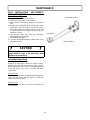
CUTTING EDGE MAINTENANCE
Verify from time to time the wearing on the cutting
edge to make sure you do not wear out the base of
the snowblower’s chassis. This cutting edge is
reversible. All you have to do is unscrew the bolts and
turn the cutting edge, reinstall and tighten the bolts
securely.
AUGERS AND FAN SHEAR BOLT
REPLACEMENT
Shear bolts are to be considered a preventive
measure and not an assured protection. Operator
vigilance is required. Thoroughly inspect the areas
where the snowblower is to be used and remove all
foreign objectsl
To avoid damage to the snowblower:
Use only the original shear bolts (grooved bolts).
#104000 in bags of 10 for the augers.
#103999 in bags of 10 for the fan.
The use of any other shear bolt will not insure any
protection and may void the warranty.
MAINTENANCE
MAINTENANCE
a) Check mounting bolts at frequent intervals for
proper tightness in order to prevent costly repairs.
Make sure your attachment is in safe working
condition.
b) Provide adequate blocking before working under
attachment when in raised position.
ADJUSTMENTS
SKID SHOE ADJUSTMENT:
Level Paved Surface: Adjust skid shoes to obtain 3/16"
to 1/4" clearance between cutting edge and surface.
Uneven or Gravel Surface: Adjust skid shoes to obtain
1/2" to 5/8" clearance between cutting edge and
surface.
LUBRICATION
Apply oil at all pivot points.
Chute Rotation System:
Oil chute base, rotation worm when necessary.
Gear box:
Check the oil annually. If necessary, add AGMA 5 EP or
SAE 90 oil..
7 WARNING 7
TO PREVENT INJURIES:
Stop the motor.
Apply parking brake.
Remove the ignition key.
Disconnect the wire from the spark plug(s) and
keep away from spark plug(s) to prevent accidental
starting.
END OF SEASON STORAGE
a) Clean snowblower and subframe thoroughly and
repaint all parts from which paint has worn.
b) List the replacement parts that will be needed for
the next season.
c) Store the snowblower and the subframe in a dry
place.
d) Follow the instructions in the Lubrication section.
La page est en cours de chargement...
La page est en cours de chargement...
La page est en cours de chargement...
La page est en cours de chargement...
La page est en cours de chargement...
La page est en cours de chargement...
La page est en cours de chargement...
La page est en cours de chargement...
La page est en cours de chargement...
La page est en cours de chargement...
La page est en cours de chargement...
La page est en cours de chargement...
La page est en cours de chargement...
La page est en cours de chargement...
La page est en cours de chargement...
La page est en cours de chargement...
La page est en cours de chargement...
-
 1
1
-
 2
2
-
 3
3
-
 4
4
-
 5
5
-
 6
6
-
 7
7
-
 8
8
-
 9
9
-
 10
10
-
 11
11
-
 12
12
-
 13
13
-
 14
14
-
 15
15
-
 16
16
-
 17
17
-
 18
18
-
 19
19
-
 20
20
-
 21
21
-
 22
22
-
 23
23
-
 24
24
-
 25
25
-
 26
26
-
 27
27
-
 28
28
-
 29
29
-
 30
30
-
 31
31
-
 32
32
-
 33
33
-
 34
34
-
 35
35
-
 36
36
-
 37
37


Bercomac C151 61576 0 _ C151 61577 0 Manuel utilisateur
- Catégorie
- Souffleuses à neige
- Taper
- Manuel utilisateur
dans d''autres langues
Documents connexes
-
Bercomac C151 61581 0 Manuel utilisateur
-
-
-
-
-
-
-
-
-
