
Bedienungsanleitung
Operating instructions
Notice utilisateurs
Kapazitiver
Niveauschalter
Capacitive level switch
Détecteur de niveau
capacitif
KNM
Sachnr. 701642/00 02/2006

Inhalt Seite
1 Bestimmungsgemäße Verwendung ---------------------------------- 2
2 Montage -------------------------------------------------------------------- 2
3 Elektrischer Anschluß ---------------------------------------------------- 3
4 Bedienung ------------------------------------------------------------------ 3
5 Programmieren ----------------------------------------------------------------3
6 Inbetriebnahme/Betrieb ------------------------------------------------ 7
1 Bestimmungsgemäße Verwendung
Kapazitiver Niveauschalter zur Überwachung von Füllständen flüssiger
Medien und trockener Schüttgüter, vorzugsweise Kunststoffgranulate.
Je nach Einstellungsart wird bei Über- bzw. Unterschreiten des durch
den Montageort gewählten Niveaus ein Schaltsignal erzeugt.
• Automatischer Abgleich auf das zu erfassende Objekt durch Pro-
grammiertaste.
2 Elektrischer Anschluß
Schalten Sie die Anlage spannungsfrei. Schließen Sie das Gerät
an (siehe Typenschild).
Adernfarben: BN = braun, BU = blau, BK = schwarz
2
2
5
34
1
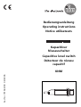
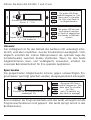
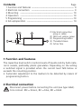
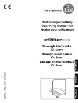
(1) Elektrischer Anschluß
(Steckverbindung oder
Anschlußleitung)
(2) LEDs rot, gelb, grün
(3) Programmiertaste
(4) Gewindehülse
(5) Aktive Fläche

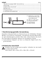
3 Montage
Montieren Sie den Näherungsschalter wie abgebildet und program-
mieren Sie ihn erst dann.
4 Bedienung
Gleichen Sie den Sensor ab. Drücken Sie dazu die Programmiertaste
mit einem stumpfen Gegenstand.
5 Programmieren
Betriebsmodus
Unmittelbar nach dem Einschalten befindet sich der Näherungsschal-
ter im Betriebsmodus. In diesem Modus sind alle normalen Sensor-
funktionen aktiv.
Darüber hinaus können Sie am Gerät folgende Einstellungen vorneh-
men:
•Abgleichmodus
Einstellung des Schaltpunktes im Leer- und Vollabgleich
•Sperrmodus
Elektronisches Schloss zur Vermeidung von Manipulationen
•Einstellung der Ausgangsfunktion als Öffner oder Schließer
3
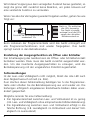
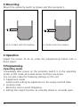
nicht medienberührend medienberührend

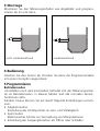
Abgleichmodus Leerabgleich
Der Sensor wird auf den leeren
Behälter abgeglichen. Erfaßt er Füll-
gut, ändert sich sein Schaltsignal.
Führen Sie dann die Schritte 1 und 2 aus.
Abgleichmodus Vollabgleich
Füllen Sie den Behälter, so daß der
Sensor das Füllgut erfaßt.
4
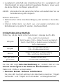
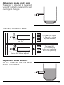
1
2
Drücken Sie die Programmiertaste für
max. 5s
Lassen Sie die Programmiertaste vor
Ablauf der 5s wieder los
Die grüne LED blinkt
(= Gerät ist im
Abgleichmodus)
Die grüne LED
leuchtet konstant
(= Gerät ist abgeglichen
und im Betriebsmodus)

Führen Sie dann die Schritte 1 und 2 aus.
Hinweis:
Der Vollabgleich ist für den Betrieb des Gerätes nicht unbedingt erfor-
derlich, wird aber empfohlen. Aus der Kombination Leerabgleich / Voll-
abgleich ermittelt der interne Mikroprozessor die optimale Lage der
Schaltschwellen zwischen beiden Zuständen. Wenn Sie also beide
Abgleichkriterien (Leer- und Vollabgleich) anwenden, erhalten Sie
maximale Betriebssicherheit für Ihre spezielle Applikation.
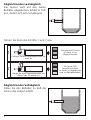
Sperrmodus
Die gespeicherten Abgleichwerte können gegen unberechtigtes Pro-
grammieren wie folgt gesichert werden (Ausgangszustand entriegelt):
Beim Loslassen der Programmiertaste wird das Gerät verriegelt und alle
Programmierfunktionen sind gesperrt. Das Gerät springt zurück in den
Betriebsmodus.
5
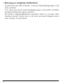
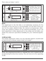
1
2
Drücken Sie die Programmiertaste
für ca.. 5 ... 10s
Lassen Sie die Programmiertaste nach
5 ... 10s wieder los
Die grüne LED blinkt
zunächst langsam (ca. 1Hz),
dann nach 5s schneller
(ca. 2Hz). Das Gerät ist
im Abgleichmodus
Die grüne LED leuchtet
kurz danach konstant
(= Gerät ist abgeglichen
und wieder im Betriebs-
modus)
1
Drücken Sie die Programmiertaste
mindestens 10s
Die grüne LED blinkt
zunächst langsam (ca. 1Hz),
dann nach 5s schneller
(ca. 2Hz),
nach 10s verlischt sie;
das Gerät ist verriegelt

Wird dieser Vorgang aus dem verriegelten Zustand heraus gestartet, so
zeigt die grüne LED zunächst keine Reaktion, um jeden Hinweis auf
eine versteckte Funktion zu vermeiden.
Wenn Sie also die Verriegelung wieder freigeben wollen, gehen Sie wie
folgt vor:
Beim Loslassen der Programmiertaste wird das Gerät entriegelt und
alle Programmierfunktionen sind wieder freigegeben. Das Gerät
springt zurück in den Betriebsmodus.
Einstellung der Ausgangsfunktion als Öffner oder Schließer
Der Schaltausgang des Gerätes kann als Öffner- oder Schließerkontakt
betrieben werden. Dazu muss das Gerät zunächst ausgeschaltet wer-
den. Um das invertierte Ausgangsverhalten zu erzeugen, wird die
Betriebsspannung mit der umgekehrten Polarität zugeschaltet.
Fehlermeldungen
Ist der Leer- oder Vollabgleich nicht möglich, blinkt die rote LED nach
dem Abgleichversuch schnell (ca. 2Hz).
Zum Löschen dieser Fehlermeldung betätigen Sie 1x die Programmier-
taste oder schalten Sie die Betriebsspannung aus und wieder ein. Die
bisherigen erfolgreich eingelesenen Einstellwerte bleiben dabei unver-
ändert gespeichert.
Mögliche Gründe für eine Fehlermeldung:
•Der Signalunterschied zwischen Leer- und Vollzustand ist zu gering
(z.B. Leer- und Vollabgleich ohne entsprechende Füllstandsänderung)
•Die Signaländerung zwischen Leer- und Vollzustand erfolgt in die
falsche Richtung (z.B. Leerabgleich im Vollzustand und darauf Voll-
abgleich im Leerzustand)
6
1
Drücken Sie die Programmiertaste
mindestens 10s
Nach ca. 10s verlöschen
alle LEDs kurzzeitig.
Das Gerät ist wieder
entriegelt und die LEDs
zeigen den aktuellen
Betriebszustand an

•Leerabgleich außerhalb des Arbeitsbereiches (z.B. Leerabgleich auf
Direktkonkakt mit einem elektrisch geerdeten Medium, etwa wenn
die aktive Fläche ins Wasser getaucht ist)
Abhilfe: Vermeiden Sie die genannten Fehler und wiederholen Sie zur
Fehlerbehebung den Abgleich.
Weitere Fehlerarten:
•Elektronischer Fehler oder Beschädigung des Gerätes im Sensorbe-
reich
•Interner Fehler (kann nur durch aus- und wieder einschalten der
Betriebsspannung gelöscht werden, Hardware-Reset)
6 Inbetriebnahme/Betrieb
Prüfen Sie, ob das Gerät sicher funktioniert. Anzeige durch LEDs.
Die rote LED zeigt keine Gerätestörung an, sondern daß sich das
interne Sensorsignal in der Nähe der Schaltschwelle befindet.
Dabei sind 2 Fälle zu unterscheiden:
•Normaler Betrieb / Sicheres Funktionieren
Die rote LED leuchtet während des Wechselns zwischen “Objekt
vorhanden” und “Objekt nicht vorhanden” vorübergehend auf.
7
LED grün
EIN = Gerät ist betriebsbereit
blinkt langsam (1Hz) = Abgleichmodus Leerabgleich
blinkt schnell (2Hz) = Abgleichmodus Vollabgleich
AUS = Sperrmodus
LED gelb AUS = Schaltausgang gesperrt
EIN = Schaltausgang leitend
LED rot blinkt schnell (2Hz) = Fehlermeldung
EIN = unsicherer Arbeitsbereich
LED gelb und rot
gemeinsam
blinken schnell (2Hz)
= Kurzschluß Schaltausgang

•Warnung vor möglicher Fehlfunktion
Leuchtet die rote LED konstant, sind die Arbeitsbedingungen nicht
mehr optimal.
Z. B. kann eine durch Schmutzablagerungen verursachte Schaltab-
standsverschiebung erkannt werden.
Sie können Gegenmaßnahmen ergreifen, bevor es zu einer Fehl-
funktion kommt. Führen Sie in z.B. einen erneuten Abgleich durch
oder reinigen Sie das Gerät.
8

Contents Page
1 Function and features ---------------------------------------------------- 9
2 Electrical connection ---------------------------------------------------- 9
3 Mounting ---------------------------------------------------------------- 10
4 Operation ---------------------------------------------------------------- 10
5 Programming ----------------------------------------------------------------10
6 Set-up/operation -------------------------------------------------------- 14
1 Function and features
The capacitive level switch monitors levels of liquids and dry bulk mate-
rial in vessels, preferably plastic granulates. Depending on the setting
a switched signal is provided when the current level falls below or
exceeds the mounting position.
•Automatic adjustment to the medium to be detected by means of
programming button.
2 Electrical connection
Disconnect power before connecting the unit (see type label).
Core colours: BN = brown, BU = blue, BK = black
9
2
5
34
1
(1) Electrical connection
(plug or cable)
(2) LEDs red, yellow, green
(3) Programming button
(4) Threaded sleeve
(5) Active face

3 Mounting
Mount the proximity switch as shown and then program it.
4 Operation
Adjust the sensor. To do so, press the programming button with a
blunt object.
5 Programming
Operating mode
Immediately after power on the proximity switch is in the operating
mode. In this mode all normal sensor functions are active.
You can also make the following settings on the unit:
•Adjustment mode
Switch point setting by adjustment to the empty and full state.
•Locking mode
Electronic lock to avoid tampering.
•Setting the output function as normally closed or normally open.
10
not in contact with the medium in contact with the medium

Adjustment mode empty state
The sensor is adjusted to the empty
vessel. If it detects material, the swit-
ched signal changes.
Then carry out steps 1 and 2.
Adjustment mode full state
Fill the vessel so that the sensor
detects the material.
11
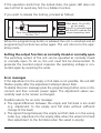
1
2
Press the programming button for
max. 5s
Release the programming button
before the 5s have elapsed
The green LED flashes
(= the unit is in the
adjustment mode)
The green LED
is lit continuously
(= the unit is adjusted
and in the operating
mode)

Then carry out steps 1 and 2.
Note:
The adjustment to the full state is not absolutely necessary for the
operation of the unit but it is recommended. On the basis of the val-
ues for the empty state/full state the internal microprocessor deter-
mines the optimum position of the switching thresholds. If you use
both adjustment criteria (adjustment to the empty and full state), you
obtain the maximum operational reliability for your individual applica-
tion.
Locking mode
The stored adjustment values can be protected against unauthorised
programming as follows (output state not locked):
When the programming button is released the unit is locked and all
programming functions are inactive. The unit returns to the operating
mode.
12
1
2
Press the programming button for
about 5 ... 10s
Release the programming button
after 5 to 10s
The green LED first flas-
hes slowly (about 1Hz),
after 5s more quickly
(about 2Hz); the unit is in
the adjustment mode
Shortly afterwards the
green LED
is lit continuously
(= the unit is adjusted
and again in the
operating mode)
1
Press the programming button
for min. 10s
The green LED first flas-
hes slowly (about 1Hz),
after 5s more quickly
(about 2Hz), after 10s it
goes out.
The unit is locked

If this operation starts from the locked state, the green LED does not
react at first to avoid any hint to a hidden function.
If you want to release the locking, proceed as follows:
When the programming button is released the unit is unlocked and all
programming functions are active again. The unit returns to the oper-
ating mode.
Setting the output function as normally closed or normally open
The switching output of the unit can be operated as normally closed
or normally open. To do so, the unit must first be disconnected. To
generate the inverted output response the operating voltage is con-
nected again by reversing the wires.
Error messages
If the adjustment to the empty or full state is not possible, the red LED
flashes quickly after the adjustment attempt (about 2Hz).
To delete this error message press the programming button once or dis-
connect and then connect power again. The adjustment values suc-
cessfully read so far remain unchanged.
Possible reasons for an error message:
•The signal difference between the empty and full state is too small
(e.g. adjustment to the empty and full state without sufficient
change of the level).
•The signal change between the empty and full state is in the wrong
order (e.g. adjustment to the empty state when the vessel is full and
then adjustment to the full state when the vessel is empty).
13
1
Press the programming button
for min. 10s
After about 10s all LEDs
go out briefly.
The unit is unlocked again
and the LEDs indicate the
current operating state

•Adjustment to the empty state outside the operating range (e.g.
adjustment to the empty state with direct contact with an electri-
cally grounded medium, e.g. if the active face is immersed in water).
Help: Avoid the above-mentioned errors and repeat the adjustment.
Further faults:
•Electronic fault or sensing zone of the unit damaged
•Internal fault (can only be deleted by disconnecting and connecting
power again, hardware reset).
6 Set-up / operation
Check the safe functioning of the unit. Display by LEDs.
The red LED indicates no malfunction of the unit, it indicates that the
internal sensor signal is near the switching threshold.
Two cases can be distinguished:
•Normal operation/safe operation
The red LED is lit temporarily during the change between "medium"
and "no medium".
14
LED green
ON = unit is ready for operation
flashes slowly (1 Hz) = adjustment mode empty state
flashes quickly (2 Hz) = adjustment mode full state
OFF = locking mode
LED yellow OFF = switching output disabled
ON = switching output enabled
LED red flashes quickly (2 Hz) = error message
ON = undefined operating range
LED yellow and red flash quickly simultaneously (2Hz)
= short circuit of the switching output

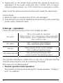
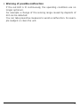
•Warning of possible malfunction
If the red LED is lit continuously, the operating conditions are no
longer optimum.
For example a change of the sensing range caused by deposits of
dirt can be detected.
You can take preventive measures to avoid a malfunction. For exam-
ple readjust or clean the unit.
15

Contenu Page
1 Fonctionnement et caractéristiques -------------------------------- 16
2 Raccordement électrique ---------------------------------------------- 16
3 Montage ------------------------------------------------------------------ 17
4 Manipulation-------------------------------------------------------------- 17
5 Programmation --------------------------------------------------------------17
6 Mise en service/Fonctionnement ------------------------------------ 21
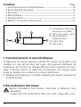
1 Fonctionnement et caractéristiques
Le détecteur de niveau capacitif contrôle les niveaux de liquides et de
matières en vrac sèches dans des cuves, des granulés plastiques de
préférence. En fonction du réglage effectué et de la position de mon-
tage, le décteur donne un signal de commutation si le niveau actuel
passe en dessous ou au dessus du niveau sélectionné.
•Réglage automatique sur le fluide à détecter par bouton-poussoir de
programmation.
2 Raccordement électrique
Mettre l'installation hors tension. Raccorder le détecteur (voir
l'étiquette).
Couleurs des fils conducteurs: BN = brun, BU = bleu, BK = noir
16
2
5
34
1
(1) raccordement électrique
(connecteur ou câble)
(2) LED rouge, jaune, verte
(3) bouton-poussoir
programmation
(4) boîtier fileté
(5) face active

3 Montage
Monter le détecteur de niveau selon la figure et le programmer ensuite.
4 Manipulation
Régler le détecteur. Pour ainsi faire, appuyer sur le bouton-poussoir
programmation avec un objet non pointu.
5 Programmation
Mode de fonctionnement
Directement après la mise sous tension le détecteur de proximité se
trouve en mode de fonctionnement. Dans ce mode, toutes les fonc-
tions standards du détecteur sont actives.
De plus, les réglages suivants peuvent être effectués sur le détecteur:
•mode de réglage
réglage du seuil de commutation sur l'état vide et l'état plein
•mode de verrouillage
blocage électronique pour éviter des manipulations non-intention-
nelles
•réglage de la fonction de sortie en normalement fermé ou norma-
lement ouvert
17
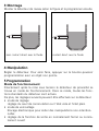
sans contact direct avec le fluide contact direct avec le fluide

Mode de réglage vide
Le détecteur est réglé sur le cuve
vide. Si le fluide est détecté, le signal
de commutation change.
Ensuite effectuer les étapes 1 et 2.
Mode de réglage plein
Remplir le cuve de sorte que le
détecteur détecte le fluide.
18
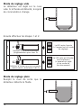
1
2
Appuyer sur le bouton-poussoir
programmation pour max. 5s
Relâcher le bouton-poussoir program-
mation avant l'écoulement des 5s
La LED verte clignote
(= l'appareil est en mode
de réglage)
La LED verte est allumée
continuellement
(= appareil est réglé
et en mode de
fonctionnement)

Ensuite effectuer les étapes 1 et 2.
Remarque:
Le réglage sur l'état plein n'est pas absolument nécessaire pour le
fonctionnement du détecteur, il est cependant recommandé. Sur la
base de la combinaison réglage vide/plein, le microprocesseur interne
peut déterminer la position optimale des seuils de commutation entre
les deux états. Si vous effectuez le réglage sur l'état vide et plein, une
fiabilité maximale pour votre application est garantie.
Mode de verrouillage
Les valeurs réglées mémorisées peuvent être protégées contre une pro-
grammation non autorisée comme suit: (état de sortie verrouillé):
Si le bouton-poussoir programmation est relâché, l'appareil est ver-
rouillé et toutes les fonctions de programmation sont bloquées. L'ap-
pareil repasse en mode de fonctionnement.
19
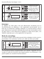
1
2
Appuyer sur le bouton-poussoir
programmation pour env. 5...10s
Relâcher le bouton-poussoir
programmation après 5...10s
D'abord la LED verte
clignote lentement
(env. 1Hz), puis après 5s
rapidement (env. 2Hz).
L'appareil est en mode
de réglage
Peu après la LED verte est
allumée continuellement
(= appareil est réglé et de
nouveau en mode de
fonctionnement)
1
Appuyer sur le bouton-poussoir pro-
grammation pendant au moins 10s
D'abord la LED verte cli-
gnote lentement (env.
1Hz), après 5s rapidement
(env. 2Hz),
après 10s elle s'éteint.
L'appareil est verrouillé

Si cette opération est effectuée en état verrouillé, la LED verte ne réa-
git d'abord pas afin d'éviter toute indication à une fonction cachée.
Si vous souhaitez débloquer le verrouillage, procédez comme suit:
Si le bouton-poussoir programmation est relâché, l'appareil est déver-
rouillé et toutes les fonctions de programmation sont de nouveau
actives. L'appareil retourne au mode de fonctionnement.
Réglage de la fonction de sortie en normalement fermé ou nor-
malement ouvert
La sortie de commutation de l'appareil peut être utilisée comme
contact normalement ouvert ou normalement fermé. D'abord l'appa-
reil doit être mis hors tension.
Pour changer la fonction de sortie, inverser la polarité de la tension
d'alimentation.
Messages d'erreur
Si le réglage sur l'état vide/plein n'est pas possible, la LED rouge cligno-
te rapidement (env. 2Hz) après la tentative de réglage.
Pour effacer ce message d'erreur, actionner le bouton-poussoir pro-
grammation une fois ou mettre l'installation brièvement hors tension.
Les valeurs de réglage mémorisées avec succès jusqu'à ce moment res-
tent inchangées.
Raisons possibles pour un message d'erreur:
•la différence de signal entre l'état vide et l'état plein est trop faible
(p.ex. réglage sur l'état vide et l'état plein sans le changement de
niveau nécessaire)
•le changement de signal entre l'état vide et l'état plein est effectué
dans le mauvais ordre (p.ex. réglage de l'état vide en état plein et
ensuite le réglage de l'état plein en état vide)
20
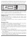
1
Appuyer sur le bouton-poussoir pro-
grammation pendant au moins 10s
Après env. 10s toutes les
LED s'éteignent briève-
ment. Ensuite l'appareil
est déverrouillé et les LED
indiquent l'état de fonc-
tionnement actuel
La page est en cours de chargement...
La page est en cours de chargement...
La page est en cours de chargement...
-
 1
1
-
 2
2
-
 3
3
-
 4
4
-
 5
5
-
 6
6
-
 7
7
-
 8
8
-
 9
9
-
 10
10
-
 11
11
-
 12
12
-
 13
13
-
 14
14
-
 15
15
-
 16
16
-
 17
17
-
 18
18
-
 19
19
-
 20
20
-
 21
21
-
 22
22
-
 23
23


dans d''autres langues
- English: IFM KN5118 Operating instructions
- Deutsch: IFM KN5118 Bedienungsanleitung
Documents connexes
Autres documents
-
 IFM Electronic Efector 200 OL Series Operating Instructions Manual
-
Legrand In One Celiane 672 15 Manuel utilisateur
-
Topcom COCOON 50 Manuel utilisateur
-
Key Automation 900RXM-41R Manuel utilisateur
-
 Reely 1456607 Mode d'emploi
-
Baumer OHDK 25G6912/S14C Mode d'emploi
-
 Roger Technology Roger H70/200AC Le manuel du propriétaire
-
 Speck pumpen Niveau BNR 300 Mode d'emploi


