ESAB Mig 410 Manuel utilisateur
- Catégorie
- Système de soudage
- Taper
- Manuel utilisateur
Ce manuel convient également à

US
FR
ES
Valid for serial no. 627-xxx-xxxx, 122-xxx-xxxx0463 315 031 US FR ES 20111205
Origo™
Mig 410
Mig 510
Manuel d'instructions
Instrucciones de uso
Instruction manual

- 2 -
Sous réserve de modifications sans avis préalable.
Reservado el derecho de cambiar las especificaciones sin previo aviso.
Rights reserved to alter specifications without notice.
AMERICAN 3............................................
FRANÇAIS 17.............................................
ESPAÑOL 31..............................................

AMERICAN
- 3 -
TOCa
Sous réserve de modifications sans avis préalable.
Reservado el derecho de cambiar las especificaciones sin previo aviso.
Rights reserved to alter specifications without notice.
1 USER RESPONSIBILITY 4............................................
2 SAFETY PRECAUTIONS 4............................................
3 INTRODUCTION 8...................................................
3.1 Equipment 8................................................................
4 TECHNICAL DATA 9.................................................
5 INSTALLATION 9....................................................
5.1 Location 10..................................................................
5.2 Assembly of components 10...................................................
5.3 Assembly of counter balance 11................................................
5.4 Electrical installation 12.......................................................
5.5 Mains power supply 12........................................................
6 OPERATION 14.......................................................
6.1 Connection and control devices 14.............................................
6.2 Start 15.....................................................................
6.3 Overheating protection 15.....................................................
6.4 Idle mode 15................................................................
6.5 Inductance 15...............................................................
7 MAINTENANCE 15....................................................
7.1 Inspection and cleaning 15....................................................
8 FAULT TRACING 16..................................................
9 ORDERING OF SPARE PARTS 16......................................
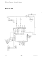
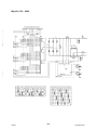
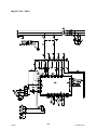
SCHEMATIC DIAGRAM 47................................................
SCHEMATIC DIAGRAM 48................................................
CONNECTION INSTRUCTION 52..........................................
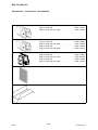
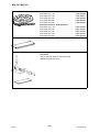
ORDERING NUMBER 54.................................................
ACCESSORIES 55.......................................................

- 4 -
US warninga
Be sure this information reaches the operator.
You can get extra copies through your supplier.
These INSTRUCTIONS are for experienced operators. If you are not fully familiar with the
principles of operation and safe practices for arc welding equipment, we urge you to read
our booklet, “Precations and Safe Practices for Arc, Cutting and Gouging, “Form 52-529.
Do NOT permit untrained persons to install, operate, or maintain this equipment. Do NOT
attempt to install or operate this equipment until you have read and fully understand these
instructions. If you do not fully understand these instructions, contact your supplier for
further information. Be sure to read the Safety Precautions before installing or operating
this equipment.
1 USER RESPONSIBILITY
This equipment will perform in conformity with the description thereof contained in this manual and
accompanying labels and/or insert when installed, operated, maintained and repaired in accordance
with the instruction provided. This equipment must be checked periodically. Malfunctioning or poorly
maintained equipment should not be used. Parts that are broken, missing, worn, distorted or
contaminated should be replaced immediately. Should such repair or replacement become necessary,
the manufacturer recommends that a telephone or written request for service advice be made to the
Authorized Distributor from whom it was purchased.
This equipment or any of its parts should not be altered without the prior written approval of the
manufacturer. The user of this equipment shall have the sole responsibility for any malfunction which
results from improper use, faulty maintenance, damage improper repair or alteration by anyone other
than the manufacturer or a service facility designated by the manufacturer.
2 SAFETY PRECAUTIONS
WARNING: These Safety Precautions are for your protection. They summarize precautionary
information from the references listed in Additional Safety Information section. Before performing any
installation or operating procedures, be sure to read and follow the safety precautions listed below as
well as all other manuals, material safety data sheets, labels, etc. Failure to observe Safety
Precautions can result in injury or death.
PROTECT YOURSELF AND OTHERS
Some welding, cutting and gouging precesses are noisy and require ear
protection. The arc, like the sun, emits ultraviolet (UV) and other radiation
and can injure skin and eyes. Hot metal can cause burns. Training in the
proper use of the processes and equipment is essential to prevent accidents.
Therefore:
1. Always wear safety glasses with side shields in any work area, even if welding helmets face
shields and goggles are also required.
US

- 5 -
US warninga
2. Use a face shield fitted with the correct filter and cover plates to protect your eyes, face, neck
and ears from sparks and rays of the arc when operating or observing operations. Warn
bystanders not to watch the arc and not to expose themselves to the rays of the electric-arc or
hot metal.
3. Wear flameproof gauntlet type gloves, heavy long-sleeve shirt, cuffless trousers, high-topped
shoes and a welding helmet or cap for protection, to protect against arc rays and hot sparks or
hot metal. A flameproof apron may also be desirable as protection against radiated heat and
sparks.
4. Hot sparks or metal can lodge in rolled up sleeves, trouser cuffs, or pockets. Sleeves and collars
should be kept buttoned and open pockets eliminated from the front of clothing.
5. Protect other personnel from arc rays and hot sparks with a suitable nonflammable partition or
curtains.
6. Use goggles over safety glasses when chipping slag or grinding. Chipped slag may be hot and
can fly far. Bystanders should also wear goggles over safety glasses.
FIRES AND EXPLOSIONS
Heat from flames and arcs can start fires. Hot slag or sparks can also cause
fires and explosions. Therefore:
1. Remove all combustible materials well away from the work area or cover the materials with a
protective nonflammable covering. Combusible materials include wood, clot, sawdust, liquid and
gas fuels, solvents, pants and coatings papper, etc.
2. Hot sparks or hot metal can fall through cracks or crevices in floors or wall openings and cause a
hidden smoldering fire or fires on the floor below. Make certain that such openings are protected
from hot sparks and metal.
3. Do not weld, cut or perform other hot work until the workpiece has been completely cleaned so
that there are no substances on the workpiece which might produce flammable or toxic vapors.
Do not do hot work on closed containers. They may explode.
4. Have fire extinguishing equipment handy for instant use, such as a garden hose, water pail, sand
bucket, or portable fire extinguisher. Be sure you are trained in its use.
5. Do not use equipment beyond its ratings. For example, overloaded welding cable can overheat
and create a fire hazard.
6. After completing operations, inspect the work area to make certain there are no hot sparks or hot
metal which could cause a later fire. Use fire watchers when necessary.
7. For additional information refer to NFPA Standard 51B, “Fire Prevention in Use of Cutting and
Welding Processes”, available from the National Fire Protection Association, Batterymarch Park,
Quincy, MA 02269.
ELECTRICAL SHOCK
Contact with live electrical parts and ground can cause severe injury or
death. DO NOT use AC welding current in damp areas, if movement is
confined, or if there is danger of falling. Therefore:
1. Be sure the power source frame (chassis) is connected to the ground system of the input power.
2. Connect the workpiece to a good electrical ground.
3. Connect the work cable to the workpiece. A poor or missing connection can expose you or others
to a fatal shock.
4. Use well-maintained equipment. Replace worn or damaged cables.
5. Keep everything dry, including clothing, work area, cables, torch/electrode holder and power
source.
6. Make sure that all parts of your bady are insulated from work and from ground.
7. Do not stand directly on metal or the earth while working in tight quarters or a damp area; stand
on dry boards or an insulating platform and wear rubber-soled shoes.
8. Put on dry, hole-free gloves before turning on the power.
9. Turn off the power before removing your gloves.
10. Refer to ANSI/ASC Standard Z49.1 (listed on next page) for specific grounding
recommendations. Do not mistake the work lead for a ground cable.
US

- 6 -
US warninga
ELECTRIC AND MAGNETIC FIELDS
May be dangerous. Electric current flowing through any conductor causes
localized Electric and Magnetic Fields (EMF). Welding and cutting current
creates EMF around welding cables and welding machines.
Therefore:
1. Welders having pacemakers should consult their physician before welding. EMF may interfere
with some pacemakers.
2. Exposure to EMF may have other health effects which are unknown.
3. Welders should use the following procedures to minimize exposure to EMF:
a. Route the electrode and work cables together. Secure them with tape when possible.
b. Never coil the torch or work cable around your body.
c. Do not place your body between the torch and work cables. Route cables on the same side
of your body.
d. Connect the work cable to the workpiece as close as possible to the area being welded.
e. Keep welding power source and cables as far away from your body as possible.
FUMES AND GASES
Fumes and gases, can cause discomfort or harm, particularly in confined
spaces. Do not breathe fumes and gases. Shielding gases can cause
asphyxiation.
Therfore:
1. Always provide adequate ventilation in the work area by natural or mechanical means. Do not
weld, cut or gouge on materials such as galvanized steel, stainless steel, cooper, zinc, lead
beryllium or cadmium unless positive mechanical ventilation is provided. Do not breathe fumes
from these materials.
2. Do not operate near degreasing and spraying operations. The heat or arc can react with
chlorinated hydrocarbon vapors to form phosgene, a highly toxic gas and other irritant gases.
3. If you develop momentary eye, nose or throat irritation while operating, this is an indication that
ventilation is not adequate. Stop work and take necessary steps to improve ventilation in the work
area. Do not continue to operate if physical discomfort persists.
4. Refer to ANSI/ASC Standard Z49.1 (see listing below) for specific ventilation recommendations.
5. WARNING: This product when used for welding or cutting, produces fumes or gases which
contain chemicals known to the State of Californa to cause birth defects and in some cases
cancer (California Health & Safety Code §25249.5 et seq.)
CYLINDER HANDLING
Cylinders, if mishandled, can rupture and violently release gas. Sudden
rupture of cylinder valve or relief device can injure or kill.
Therefore:
1. Use the proper gas for the process and use the proper pressure reducing regulator designed to
operate from the compressed gas cylinder. Do not use adaptors. Maintain hoses and fittings in
good condition. Follow manufacturer's operating instructions for mounting regulator to a
compressed gas cylinder.
2. Always secure cylinders in an upright position by chain or strap to suitable hand trucks,
undercarriages, benches, wall, post or racks. Never secure cylinders to work tables or fixtures
where they may become part of an electrical circuit.
3. When not in use, keep cylinder valves closed. Have valve protection cap in place if regulator is
not connected. Secure and move cylinders by using suitable hand trucks.
4. Locate cylinders away from heat, sparks and flames. Never strike an arc on a cylinder.
5. For additional information, refer to CGA Standard P-1, “Precations for Safe Handling of
Comporessed Gases in Cylinders”, which is available from Compressed Gas Association, 1235
Jefferson Davis Highway, Arlington, VA 22202.
US

- 7 -
US warninga
EQUIPMENT MAINTENANCE
Faulty or improperly maintained equipment can cause injury or death. Therefore:
1. Always have qualified personnel perform the installaion, troubleshooting and maintenance work.
Do not perform any electrical work unless you are qualified to perform such work.
2. Before performing any maintenance work inside a power source, disconnect the power source
from the incoming electrical power.
3. Maintain cables, grounding wire, connections, power cord and power supply in safe working
order. Do not operate any equipment in faulty condition.
4. Do not abuse any equipment or accessories. Keep equipment away from heat sources such as
furnaces, wet conditions such as water puddles, oil or grease, corrosive atmospheres and
inclement weather.
5. Keep all safety devices and cabinet covers in position and in good repair.
6. Use equipment only for its intended purpose. Do not modify it in any manner.
ADDITIONAL SAFETY INFORMATION
For more information on safe practices for electric arc welding and cutting equipment,
ask your supplier for a copy of “Precautions and Safe Practices for Arc Welding,
Cutting and Gouging”, Form 52-529.
The following publications, which are available from the American Welding Society, 550 N.W. LeJuene
Road, Miami, FL 33126, are recommended to you:
1. ANSI/ASC Z49.1 - “Safety in Welding and Cutting”
2. AWS C5.1 . “Recommended Practices for Plasma Arc Welding”
3. AWS C5.2 - “Recommended Practices for Plasma Arc Cutting“
4. AWS C5.3 - “Recommended Practices for Air Carbon, Arc Gouging and Cutting”
5. AWS C5.5 - “Recommended Practices for Gas Tungsten Arc Welding”
6. AWS C5.6 - “Recommended Practices for Gas Metal Arc welding”
7. AWS SP - “Safe practices” - Reprint, Welding Handbook
8. ANSI/AWS F4.1 - “Recommended Safe Practices for Welding and Cutting of Containers That
Have Held Hazardous Substances”
MEANING OF SYMBOLS
As used throughout this manual: Means Attention! Be Alert!
Means immediate hazards which, if not avoided, will result in
immediate, serious personal injury or loss of life.
Means potential hazards which could result in personal injury or loss
of life.
Means hazards which could result in minor personal injury.
US

© ESAB AB 2011
- 8 -
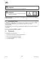
ba58ae
This product is solely intended for arc welding. Any other use may result in personal
injury and / or equipment damage.
Read and understand the instruction manual
before installing or operating.
ESAB can provide you with all necessary welding protection and accessories.
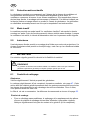
3 INTRODUCTION
The Mig 410 and Mig 510 are step-controlled power sources designed for
MIG/MAG-welding together with wire feed units Feed 302, 304, 484 and
YardFeed 200.
The power sources are fan-cooled and equipped with thermal overload protection.
ESAB's accessories for the product can be found on page 55.
3.1 Equipment
The power source is supplied with:
S 5m return cable with return clamp
S Shelf for gas cylinder
S Guide pin for wire feed unit
S Instruction manual
US

© ESAB AB 2011
- 9 -
ba58ae
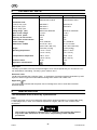
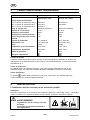
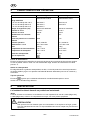
4 TECHNICAL DATA
Mig 410 Mig 510
Voltage 230/400-415/500V 350 Hz
230/440-460 360Hz
230/400-415/500V 350 Hz
230/440-460 360Hz
Permissible load
at 100 % duty cycle
280 A/28 V 390 A/33,5 V
at 60 % duty cycle 365 A/32 V 500 A/39 V
at 50 % duty cycle 400 A/34 V -
Setting range (DC) 50A/16.5V-400A/34V 50A/16.5V-400A/39V
Open circuit voltage 17-45 V 17-50 V
Open circuit power 360 W 440 W
Efficiency at max current 71% 82%
Power factor at max current 0.98 0.92
Control voltage 42 V, 50/60 Hz 42 V, 50/60 Hz
Dimensions LxWxH 32 x 21.8 x 36.5”
(812 x 552 x 925 mm)
32 x 21.8 x 36.5”
(812 x 552 x 925 mm)
Weight 319.6 lbs (145 kg) 474 lbs (215kg)
Operating temperature - 50 to + 104°F
(-10 to +40°C)
- 50 to + 104°F
(-10 a +40°C)
Transportation temperature -68 to -131°F
(-20 to +55°C)
-68 to -131°F
(-20 a +55°C)
Enclosure class IP 23 IP 23
Application classification
Duty cycle
The duty cycle refers to the time as a percentage of a ten-minute period that you can weld at a cer
tain load without overloading. The duty cycle is valid for 104° F.
Enclosure class
The IP code indicates the enclosure class, i. e. the degree of protection against penetration by solid
objects or water. Equipment marked IP 23 is designed for indoor and outdoor use.
Application class
The symbol indicates that the power source is designed for use in areas with increased
electrical hazard.
5 INSTALLATION
The installation must be done by a professional.
Note!
Connect the power source to the electricity mains with a network impedance of 0.230 (Mig 410w),
0.155 (Mig 510w) or lower. If the network impedance is higher, there is a risk of flicker in the
illuminators.
This product is intended for industrial use. In a domestic environment this product
may cause radio interference. It is the user's responsibility to take adequate
precautions.
US

© ESAB AB 2011
- 10 -
ba58ae
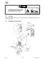
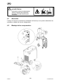
STRAPS MUST BE USED WHEN LIFTING
THE POWER SOURCE. THE HANDLE IS
ONLY INTENDED FOR PULLING IT.
5.1 Location
Position the welding power source in such a way that its cooling air inlets and outlets
are not obstructed.
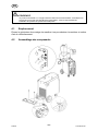
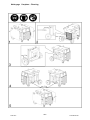
5.2 Assembly of components
US

© ESAB AB 2011
- 11 -
ba58ae
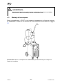
DURING TRANSPORT, THE REAR WHEELS OF THE POWER SOURCE ARE IN THEIR
FORWARD POSITION. BEFORE USE, PLACE THE WHEELS IN THEIR REAR
POSITION.
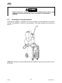
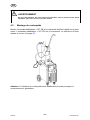
5.3 Assembly of counter balance
Assemble the stabiliser + CB KIT if the counter balance is to be installed on the power
source. The stabiliser + CB KIT is an accessory. The order number can be found on
page 55.
Attention! Using the counter balance without stabiliser may cause the power source
to tip over.
US

© ESAB AB 2011
- 12 -
ba58ae
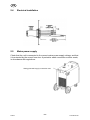
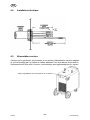
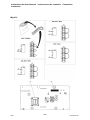
5.4 Electrical installation
5.5 Mains power supply
Check that the unit is connected to the correct mains power supply voltage, and that
it is protected by the correct fuse size. A protective earth connection must be made,
in accordance with regulations.
Rating plate with supply connection data
US

© ESAB AB 2011
- 13 -
ba58ae
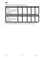
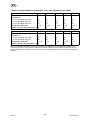
Recommended fuse sizes and minimum cable areas
Mig 410 350 Hz 350/60 Hz 350 Hz 360 Hz 360 Hz
Voltage V 230 400/415 500 230 440/460
Current A
at 100% duty cycle 28 16 13 28 14
at 60% duty cycle 42 24 19 41 21
at 50% duty cycle 45 28 20 45 22
Cable area mm
2
4 x 6 4 x 2.5 4 x 2.5 4 x 6 4 x 2.5
Fuse, slow A 25 20 20 25 20
Mig 510 350 Hz 350/60 Hz 350 Hz 360 Hz 360 Hz
Voltage V 230 400/415 500 230 440/460
Current A
at 100% duty cycle 43 25 20 43 23
at 60% duty cycle 68 39 31 68 35
Cable area mm
2
4 x 16 4 x 6 4 x 6 4 x 16 4 x 6
Fuse, slow A 63 35 35 63 25
NB: The mains cable areas and fuse sizes as shown above are in accordance with Swedish
regulations. They may not be applicable in other countries: make sure that the cable area and fuse
sizes comply with the relevant national regulations.
US

© ESAB AB 2011
- 14 -
ba58ae
6 OPERATION
General safety regulations for the handling of the equipment can be found on
page 4. Read through before you start using the equipment!
FASTEN THE EQUIPMENT - PARTICULARLY IF
THE GROUND IS UNEVEN OR SLOPING.
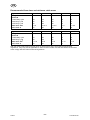
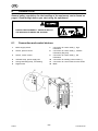
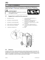
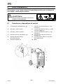
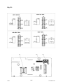
6.1 Connection and control devices
1 Mains supply switch 7 Connection for return cable (-), high
inductance
2 Switch, precise control 8 Connection for return cable (-), medium
inductance (Mig 510)
3 Switch, coarse control 9 Connection for return cable (-), low
inductance
4 Indicator lamp, power supply ON 10 Connection for welding current cable (+)
5 Orange indicating lamp, overheating 11 Connection for control cable for wire feeder
6 Digital meter 12 MCB
US

© ESAB AB 2011
- 15 -
ba58ae
6.2 Start
When switched on, the indicator lamps are checked for 2 seconds. Normally, if the
power source has not overheated, it should start to work in idle mode, which is
indicated by the supply-ON lamp flashing. The fan stops.The fan starts once welding
starts.
6.3 Overheating protection
The power source has 2-step control of the fan speed and overheating protection. If
the temperature crosses the threshold point, the fan starts to operate with increased
speed. If the internal temperature becomes too high, the welding is interrupted and
disabled. This is indicated by the orange indicating lamp on the front of the unit being
permanently lit. The unit resets automatically once the temperature drops.
6.4 Idle mode
The machine has an idle mode. The fan switches off 5 min after welding has finished
or 5 min after running at a decreased speed without welding. Once the fan has
switched off, the power-supply lamp on the front panel flashes.
6.5 Inductance
Higher inductance produces a more flowing weld and less spatter. Lower inductance
produces a harsher sound and a stable, concentrated arc.
7 MAINTENANCE
Regular maintenance is important for safe, reliable operation.
Supplier warranty is void if customer attempts any work on product during the
warranty period.
7.1 Inspection and cleaning
Power source
Check regularly that the power source is free from dirt.
The power source should be regularly blown clean using dry compressed air at reduced
pressure, see page 47. This should be done more frequently in dirty environments.
Otherwise the air inlet/outlet may become blocked and cause overheating. To avoid
this you can use an air filter.
The air filter is an accessory. The order number can be found on page 55.
US

© ESAB AB 2011
- 16 -
ba58ae
Welding gun
S Cleaning and replacement of the welding gun's wear parts should take place at
regular intervals in order to achieve trouble-free wire feed. Blow the wire guide
clean regularly and clean the contact tip.
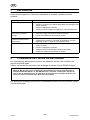
8 FAULT TRACING
Try these recommended checks and inspections before sending for an authorised
service technican.
Type of fault Actions
No arc S Check that the mains power supply switch is turned on.
S Check that the welding current supply and return cables are
correctly connected.
S Check that correct current value is set.
S Check to see whether the MCB has tripped.
Welding current is interrupted
during welding
S Check whether the thermal overload trip has been triggered
(indicated by the orange lamp on the front).
S Check the main power supply fuses.
Thermal overload trips
trigger frequently
S Check to see whether the air filters are clogged.
S Make sure that you are not exceeding the rated data for the
power source (i.e. that the unit is not being overloaded).
Poor welding performance S Check that the welding current supply and return cables are
correctly connected.
S Check that the correct current value is set.
S Check that the correct welding wires are being used.
S Check the main power supply fuses.
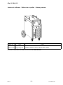
9 ORDERING OF SPARE PARTS
Repair and electrical work should be performed by an authorized ESAB service
personnel. Use only ESAB original replacement and wear parts.
Mig 410, Mig 510 is designed and tested in accordance with the international and Euro
pean standards IEC/EN 60974-1 and IEC/EN 60974-10. It is the obligation of the servi
ce unit which has carried out the service or repair work to make sure that the product
still conforms to the said standard.
When ordering replacement parts, order by part number and part name, as
illustrated on the figure. Always provide the series or serial number on the unit on
which the parts will be used. The serial number is stamped on the rating plate.
US

FRANÇAIS
- 17 -
TOCf
1 MESURES DE SECURITE 18...........................................
2 INTRODUCTION 22...................................................
2.1 Équipement 22...............................................................
3 CARACTÉRISTIQUES TECHNIQUES 23.................................
4 INSTALLATION 23....................................................
4.1 Emplacement 24.............................................................
4.2 Assemblage des composants 24...............................................
4.3 Montage du contrepoids 25....................................................
4.4 Installation électrique 26.......................................................
4.5 Alimentation secteur 26.......................................................
5 FONCTIONNEMENT 28................................................
5.1 Appareils de contrôle et de connexion 28........................................
5.2 Démarrer 28.................................................................
5.3 Protection anti-surchauffe 29..................................................
5.4 Mode inactif 29..............................................................
5.5 Inductance 29...............................................................
6 ENTRETIEN 29.......................................................
6.1 Contrôle et nettoyage 29......................................................
7 DÉPANNAGE 30......................................................
8 COMMANDE DE PIÈCES DE RECHANGE 30............................
SCHÉMA 48.............................................................
INSTRUCTIONS DE BRANCHEMENT 52...................................
NUMÉRO DE RÉFÉRENCE 54............................................
ACCESSOIRES 55.......................................................

- 18 -
US warningf
1 MESURES DE SECURITE
ATTENTION : ces règles de sécurité ont pour objet d'assurer votre protection. Elles constituent
une synthèse des mesures de sécurité contenues dans les ouvrages de référence repris au chapitre
Informations complémentaires relatives à la Sécurité. Avant toute installation ou utilisation du matériel,
veillez à lire et à respecter les règles de sécurité énoncées ci-dessous ainsi que dans les divers
manuels, fiches de sécurité du matériel, étiquettes, etc. Le non-respect de ces précautions risque
d'entraîner des blessures graves ou mortelles.
PROTECTION INDIVIDUELLE ET DE L'ENTOURAGE
Certains procédés de soudage, découpage et gougeage sont bruyants et
requièrent le port de protections auditives. L'arc, tout comme le soleil, émet
des ultraviolets (UV) et d'autres rayonnements susceptibles de provoquer des
lésions oculaires et dermatologiques. Le métal chaud peut être à l'origine de
brûlures. Une formation à l'utilisation correcte des procédés et équipements
est essentielle pour prévenir les accidents. En conséquence :
1. Porter impérativement des lunettes avec écrans latéraux dans les zones de travail, même
lorsque le port du casque de soudage, de l'écran facial et des lunettes de protection est
obligatoire
2. Tant pour exécuter les travaux que pour y assister, porter un écran facial muni de plaques
protectrices et de verres filtrants appropriés pour protéger les yeux, le visage, le cou et les
oreilles des étincelles et du rayonnement de l'arc. Avertir les personnes se trouvant à proximité
qu'elles ne doivent pas regarder l'arc, ni s'exposer à son rayonnement ou à celui du métal
incandescent.
3. Porter des gants ignifuges à crispins, une tunique épaisse à longues manches, des pantalons
sans rebord, des chaussures à embout d'acier et un casque de soudage ou une casquette pour
se protéger du rayonnement de l'arc, des étincelles et du métal incandescent. Le port d'un tablier
ininflammable est également recommandé afin de se protéger des étincelles et du rayonnement
thermique.
4. Les étincelles ou projections de métal en fusion risquent de se loger dans les manches
retroussées, les bords relevés de pantalons ou dans les poches. Il convient donc de boutonner
complètement les manches et le col, et de porter des vêtements sans poches à l'avant.
5. Protéger du rayonnement de l'arc et des étincelles les personnes se trouvant à proximité à l'aide
d'un écran ou d'un rideau ininflammable approprié.
6. Porter des oculaires et des lunettes de protection pendant le meulage du laitier. Les particules
meulées, souvent brûlantes, peuvent être projetées à des distances importantes, de sorte que
les personnes se trouvant à proximité doivent également porter des lunettes de protection.
INCENDIES ET EXPLOSIONS
La chaleur dégagée par les flammes et les arcs peuvent être à l'origine
d'incendies. Le laitier incandescent et les étincelles peuvent également
provoquer incendies et explosions. En conséquence :
1. Éloigner suffisamment tous les matériaux combustibles de la zone de travail ou les recouvrir
complètement d'une bâche ignifuge. Ce type de matériaux comprend le bois, les vêtements, la
sciure, les carburants sous forme liquide et gazeuse, les peintures, les enduits, le papier, etc.
2. Les étincelles ou projections de métal en fusion peuvent tomber dans les fissures du sol ou des
murs et déclencher une combustion lente dans les planchers ou à l'étage inférieur. Veiller à
protéger ces ouvertures pour que les étincelles et projections n'y pénètrent pas.
3. Ne pas procéder à des travaux de soudage, de découpage et autres travaux à chaud tant que la
surface n'est pas complètement nettoyée et débarrassée des substances susceptibles de
produire des vapeurs inflammables ou toxiques. Ne pas effectuer de travaux à chaud sur des
conteneurs fermés pour éviter tout risque d'explosion.
4. Conserver à portée de main un équipement d'extinction – tuyau d'arrosage, seau d'eau ou de
sable, extincteur portatif, etc. et s'assurer d'en connaître l'utilisation.
5. Ne pas utiliser l'équipement au-delà de ses spécifications. Par exemple, un câble de soudage
surchargé est susceptible de surchauffer et d'être à l'origine d'un incendie.
FR

- 19 -
US warningf
6. Une fois le travail terminé, inspecter la zone de travail pour s'assurer qu'aucune étincelle ou
projection de métal ne risque de déclencher un incendie. Le cas échéant, utiliser des systèmes
de détection d'incendie.
7. Pour toute information supplémentaire, voir la norme NFPA 51B relative à la prévention des
incendies lors de travaux de découpage et de soudage, disponible auprès de la National Fire
Protection Association, Batterymarch Park, Quincy, MA 02269 – USA.
CHOC ELECTRIQUE
Tout contact avec des éléments sous tension et la masse peut provoquer des
blessures graves ou mortelles. NE PAS utiliser de courant de soudage CA
dans des zones humides, des lieux exigus ou lorsqu'il existe un risque de
chute. En conséquence :
1. Vérifier que le châssis du générateur est bien relié au dispositif de mise à la masse de
l'alimentation.
2. Assurer une mise à la masse correcte de la pièce à souder.
3. Connecter le câble de soudage à la pièce à souder. Un raccordement médiocre ou inexistant
constitue un risque mortel pour l'utilisateur et son entourage.
4. Utiliser du matériel correctement entretenu. Remplacer les câbles usés ou endommagés.
5. Empêcher l'apparition de toute humidité, notamment sur les vêtements, dans la zone de travail,
sur les câbles, la torche de soudage, le porte-électrode et le générateur.
6. S'assurer que le corps est totalement isolé de la pièce à souder et de la masse.
7. Éviter tout contact direct avec du métal ou la masse lors de travaux dans des endroits exigus et
en zone humide ; se tenir sur des panneaux ou sur une plate-forme isolante et porter des
chaussures à semelles en caoutchouc.
8. Enfiler des gants secs et sans trous avant de mettre l'équipement sous tension.
9. Mettre l'équipement hors tension avant de retirer les gants.
10. Voir la norme ANSI/ASC Z49.1 (voir page suivante) pour les recommandations de mise à la
masse. Ne pas confondre le câble de soudage et le câble de masse.
CHAMPS ELECTRIQUES ET MAGNETIQUES
Danger. Le courant électrique parcourant les conducteurs génère localement
des champs électriques et magnétiques (EMF). Le courant de soudage et de
découpe crée des EMF autour des câbles de soudage et des postes à souder.
En conséquence :
1. Les porteurs de stimulateurs cardiaques consulteront leur médecin avant d'effectuer des travaux
de soudage. Les EMF peuvent en effet provoquer des interférences.
2. L'exposition aux EMF peut également avoir des effets méconnus sur la santé.
3. Les soudeurs respecteront les procédures suivantes pour réduire l'exposition aux EMF :
a. Rassembler en faisceau les câbles de soudage et d'électrode. Si possible, les attacher avec
du ruban adhésif.
b. Ne jamais enrouler le câble de la torche ou le câble de soudage autour du corps.
c. L'utilisateur ne doit jamais se trouver entre le câble de la torche et le câble de soudage.
Faire passer tous les câbles du même côté du corps.
d. Connecter le câble de soudage à la pièce à souder, au plus près de l'endroit du soudage.
e. S'éloigner au maximum du générateur et des câbles.
FR

- 20 -
US warningf
FUMEES ET GAZ
L'inhalation des fumées et gaz peut provoquer des malaises et des
dommages corporels, surtout lors de travaux dans les espaces confinés. Ne
pas les respirer. Les gaz inertes peuvent causer l'asphyxie.
En conséquence :
1. Assurer une aération adéquate de la zone de travail par une ventilation naturelle ou mécanique.
Ne pas effectuer de travaux de soudage, découpage ou gougeage sur des matériaux tels que
l'acier galvanisé, le cuivre, le zinc, le plomb, le béryllium et le cadmium en l'absence d'une
ventilation mécanique adéquate. Ne pas inhaler les fumées dégagées par ces matériaux.
2. Ne pas travailler à proximité d'opérations de dégraissage et de pulvérisation étant donné que la
chaleur dégagée et l'arc peut réagir avec les hydrocarbures chlorés pour former du phosgène –
un gaz particulièrement toxique – et d'autres gaz irritants.
3. Une irritation momentanée des yeux, du nez ou de la gorge provoquée par les travaux est le
signe d'une ventilation inappropriée. Dans ce cas, il convient d'arrêter le travail et de prendre les
mesures nécessaires pour améliorer l'aération. Ne pas poursuivre le travail si le malaise persiste.
4. Voir la norme ANSI/ASC Z49.1 (voir ci-dessous) pour les recommandations de ventilation.
5. ATTENTION : utilisé dans des opérations de soudage et de découpage, ce produit dégage des
fumées et gaz qui contiennent des substances chimiques reconnues par l'État de Californie
comme pouvant être à l'origine de malformations congénitales et de cancers (California Health &
Safety Code §25249.5 et seq.).
MANIPULATION DES BOUTEILLES DE GAZ
Une erreur de manutention des bouteilles de gaz peut les endommager et
entraîner une libération violente du gaz. La rupture soudaine de la soupape
ou du détendeur peut provoquer des blessures graves ou mortelles.
En conséquence :
1. Utiliser le gaz approprié à la pression adéquate, celle-ci étant réglée par un détendeur adapté au
type de bouteille utilisée. Ne pas utiliser d'adaptateurs. Garder les tuyaux et accessoires en bon
état. Pour le montage du détendeur sur une bouteille de gaz comprimé, suivre les instructions du
fabricant.
2. Fixer les bouteilles verticalement – au moyen d'une chaîne ou d'une sangle – à un chariot à bras,
un châssis de roulement, un banc, un mur, un piquet ou un rack. Ne jamais attacher les
bouteilles aux établis et éléments susceptibles de les intégrer à un circuit électrique.
3. Conserver les bouteilles fermées lorsqu'elles ne sont pas utilisées. Les fermer par un bouchon
lorsqu'elles ne sont pas raccordées. Attacher et déplacer les bouteilles à l'aide de chariots
adéquats.
4. Éloigner les bouteilles des sources de chaleur, d'étincelles et de flammes nues. Ne jamais
déclencher d'arc sur une bouteille de gaz.
5. Pour plus d'informations sur les précautions d'utilisation des bouteilles de gaz comprimé, voir la
norme CGA P-1, disponible auprès de la Compressed Gas Association, 1235 Jefferson Davis
Highway, Arlington, VA 22202 – USA.
ENTRETIEN DE L'EQUIPEMENT
Un équipement mal entretenu peut provoquer des blessures graves ou mortelles. En
conséquence :
1. Confier l'installation, les dépannages et l'entretien à du personnel qualifié. Ne pas effectuer de
travaux électriques si vous ne possédez pas les compétences requises.
2. Mettre l'équipement hors tension avant toute intervention d'entretien sur le générateur.
3. Maintenir en bon état de fonctionnement les câbles, câbles de masse, connexions, cordons
d'alimentation et générateurs. Ne jamais utiliser d'équipements défectueux.
4. Ne jamais surcharger les équipements et accessoires. Conserver les équipements à l'écart des
sources de chaleur – notamment des fours –, des flaques d'eau, des traces d'huile ou de graisse,
des atmosphères corrosives et des intempéries.
5. Laisser en place tous les dispositifs de sécurité et tous les panneaux du tableau de commande
en veillant à les garder en bon état.
6. Utiliser l'équipement conformément à l'usage prévu ; n'y apporter aucune modification
quelconque.
FR
La page est en cours de chargement...
La page est en cours de chargement...
La page est en cours de chargement...
La page est en cours de chargement...
La page est en cours de chargement...
La page est en cours de chargement...
La page est en cours de chargement...
La page est en cours de chargement...
La page est en cours de chargement...
La page est en cours de chargement...
La page est en cours de chargement...
La page est en cours de chargement...
La page est en cours de chargement...
La page est en cours de chargement...
La page est en cours de chargement...
La page est en cours de chargement...
La page est en cours de chargement...
La page est en cours de chargement...
La page est en cours de chargement...
La page est en cours de chargement...
La page est en cours de chargement...
La page est en cours de chargement...
La page est en cours de chargement...
La page est en cours de chargement...
La page est en cours de chargement...
La page est en cours de chargement...
La page est en cours de chargement...
La page est en cours de chargement...
La page est en cours de chargement...
La page est en cours de chargement...
La page est en cours de chargement...
La page est en cours de chargement...
La page est en cours de chargement...
La page est en cours de chargement...
La page est en cours de chargement...
La page est en cours de chargement...
La page est en cours de chargement...
La page est en cours de chargement...
-
 1
1
-
 2
2
-
 3
3
-
 4
4
-
 5
5
-
 6
6
-
 7
7
-
 8
8
-
 9
9
-
 10
10
-
 11
11
-
 12
12
-
 13
13
-
 14
14
-
 15
15
-
 16
16
-
 17
17
-
 18
18
-
 19
19
-
 20
20
-
 21
21
-
 22
22
-
 23
23
-
 24
24
-
 25
25
-
 26
26
-
 27
27
-
 28
28
-
 29
29
-
 30
30
-
 31
31
-
 32
32
-
 33
33
-
 34
34
-
 35
35
-
 36
36
-
 37
37
-
 38
38
-
 39
39
-
 40
40
-
 41
41
-
 42
42
-
 43
43
-
 44
44
-
 45
45
-
 46
46
-
 47
47
-
 48
48
-
 49
49
-
 50
50
-
 51
51
-
 52
52
-
 53
53
-
 54
54
-
 55
55
-
 56
56
-
 57
57
-
 58
58


ESAB Mig 410 Manuel utilisateur
- Catégorie
- Système de soudage
- Taper
- Manuel utilisateur
- Ce manuel convient également à
dans d''autres langues
- English: ESAB Mig 410 User manual
- español: ESAB Mig 410 Manual de usuario
Documents connexes
-
ESAB Origo™Mig 4002cw Manuel utilisateur
-
-
-
-
-
ESAB Mig 510 Origo™ Manuel utilisateur
-
ESAB PowerCut 400 Manuel utilisateur
-
-
-
ESAB PowerCut 700 PT-39 Manuel utilisateur