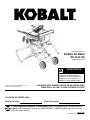
Kobalt KT10152 Manuel utilisateur
- Catégorie
- Outils électroportatifs
- Taper
- Manuel utilisateur

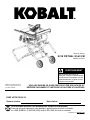
10-IN TABLE SAW
PH19148
Kobalt is a trademark of LF, LLC. All rights
reserved.
ATTACH YOUR RECEIPT HERE
Serial Number Purchase Date
kobalttools.com
MODEL #KT10152
Français p. 51
Español p. 102
ITEM #1303497
Questions, problems, missing parts? Before returning to your retailer, call our customer
service department at 1-888-3KOBALT (1-888-356-2258), 8 a.m. - 8 p.m., EST, Monday - Friday.
WARNING
To reduce risk of serious injury,
thoroughly read and comply with
all warnings and instructions in
this manual and on product.
KEEP THIS MANUAL NEAR YOUR SAW FOR EASY
REFERENCE AND TO INSTRUCT OTHERS

2
kobalttools.com
TABLE OF CONTENTS
Package Contents ............................................................................................................................ 3
Hardware Contents........................................................................................................................... 4
Safety Information ............................................................................................................................ 5
Power Connection ...........................................................................................................................12
Product Specications .....................................................................................................................13
Assembly Instructions......................................................................................................................14
Unpacking ..................................................................................................................................15
Table Stand Assembly ...............................................................................................................15
Riving Knife Installation and Positioning ....................................................................................21
Blade Installation .......................................................................................................................22
Anti-Kickback Pawls Installation ................................................................................................23
Blade Guard Installation ............................................................................................................24
Folding Leg Stand .....................................................................................................................25
Before Operating .............................................................................................................................26
Operating Components .............................................................................................................26
Switch Assembly ........................................................................................................................26
Blades ........................................................................................................................................27
Rip Fence ..................................................................................................................................28
Miter Gauge ...............................................................................................................................29
Slide Table Extension ................................................................................................................30
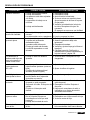
Cutting Aids ...............................................................................................................................31
How to Make a Push Stick...............................................................................................................32
How to Make a Featherboard ..........................................................................................................33
How to Make a Push Block..............................................................................................................33
How to Make Auxuiliary Fence ........................................................................................................34
Operating Instructions .....................................................................................................................35
Through-Cuts with Single Blades ..............................................................................................35
Cutting Tips ................................................................................................................................35
Making Cuts ...............................................................................................................................35
Types of Cuts .............................................................................................................................36
Dados and Other Non-Through-Cuts .......................................................................................39
Adjustments .....................................................................................................................................40
Placing Knife in Lowered Position .............................................................................................40
Replacing Blade ........................................................................................................................41
Riving Knife and Saw Blade Alignment .....................................................................................42
Healing (Paralleling) Blade to Miter Gauge Groove ..................................................................44
Setting Blade at 0° and 45° .......................................................................................................45
Adjusting Bevel Indicator ...........................................................................................................46
Checking Alignment of Rip Fence to Miter Slot .........................................................................46
Accessory Storage ..........................................................................................................................46
Care and Maintenance ....................................................................................................................47
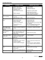
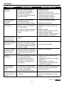
Troubleshooting ...............................................................................................................................48
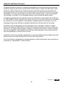
Warranty ..........................................................................................................................................49
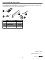
Replacement Parts List ...................................................................................................................50

3
kobalttools.com
3
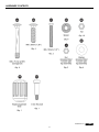
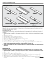
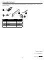
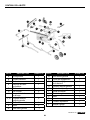
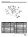
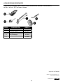
PACKAGE CONTENTS
PART DESCRIPTION QUANTITY
A Blade guard 1
B Anti-kickback pawls 1
D Push stick 1
E Side table extension 1
F Closed end wrench 1
G Open end wrench 1
H Side extension lock 1
I1, I2 Right and left handles 2
J Lower right leg 1
K Wheel 2
M Left front leg 1
PART DESCRIPTION QUANTITY
N Left rear leg 1
O Release lever 1
P Height adjusting wheel 1
R Left leg cross piece 1
S Left leg end 1
T Rip fence 1
U Miter gauge 1
V Table 1
W Blade 1
X Riving knife 1
Y Throat plate 1

4
kobalttools.com
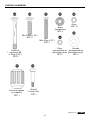
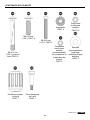
HARDWARE CONTENTS

5
kobalttools.com
SAFETY INFORMATION
IMPORTANT SAFETY INSTRUCTIONS
WARNING
CAREFULLY READ AND FOLLOW ALL WARNINGS AND INSTRUCTIONS ON YOUR PRODUCT
AND IN THIS MANUAL. SAVE THIS MANUAL. MAKE SURE ALL USERS ARE FAMILIAR WITH
ITS WARNING AND INSTRUCTIONS WHEN USING THE TOOL. Improper operation, maintenance
or modication of tools or equipment could result in serious injury and/or property damage.
If you have any questions or concerns relative to the use of your tool or the contents of this
manual, stop using the tool and contact customer service at 1-888-3KOBALT (1-888-356-2258),
8 a.m. - 8 p.m., EST, Monday - Friday.
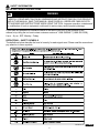
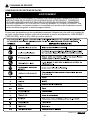
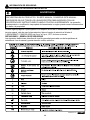
DEFINITIONS – SAFETY SYMBOLS
The denitions below describe the level of severity for each signal word. Please read the manual and
pay attention to these symbols.

6
kobalttools.com
SAFETY INFORMATION
1) Work area safety
a) Keep work area clean and well lit. Cluttered or dark areas invite accidents.
b) Do not operate power tools in explosive atmospheres, such as in the presence of ammable
liquids, gases or dust. Power tools create sparks which may ignite the dust or fumes.
c) Keep children and bystanders away while operating a power tool. Distractions can cause you
to lose control.
2) Electrical safety
a) Power tool plugs must match the outlet. Never modify the plug in any way. Do not use any
adapter plugs with earthed (grounded) power tools. Unmodied plugs and matching outlets will
reduce risk of electric shock.
b) Avoid body contact with earthed or grounded surfaces, such as pipes, radiators, ranges and
refrigerators. There is an increased risk of electric shock if your body is earthed or grounded.
c) Do not expose power tools to rain or wet conditions. Water entering a power tool will increase
the risk of electric shock.
d) Do not abuse the cord. Never use the cord for carrying, pulling or unplugging the power
tool. Keep cord away from heat, oil, sharp edges or moving parts. Damaged or entangled cords
increase the risk of electric shock.
e) When operating a power tool outdoors, use an extension cord suitable for outdoor use. Use
of a cord suitable for outdoor use reduces the risk of electric shock.
f) If operating a power tool in a damp location is unavoidable, use a RESIDUAL CURRENT
DEVICE (RCD) protected supply. Use of an RCD reduces the risk of electric shock.
DANGER
Indicates an imminently hazardous situation which, if not avoided, will result in death or serious injury.
WARNING
Indicates a potentially hazardous situation which, if not avoided, could result in death or serious injury.
CAUTION
Indicates a potentially hazardous situation which, if not avoided, may result in minor or moderate injury.
NOTICE
Indicates a practice not related to personal injury which, if not avoided, may result in property damage.
GENERAL POWER TOOL SAFETY
WARNING
WARNING Read all safety warnings, instructions, illustrations and specications provided
with this power tool. Failure to follow all instructions listed below may result in electric shock, re
and/or serious injury.
Save all warnings and instructions for future reference.
The term "power tool"in the warnings refers to your mains-operated (corded) power tool or BATTERY
operated (cordless) power tool.

7
kobalttools.com
3) Personal safety
a) Stay alert, watch what you are doing and use common sense when operating a power tool. Do not
use a power tool while you are tired or under the inuence of drugs, alcohol or medication. A moment of
inattention while operating power tools may result in serious personal injury.
b) Use personal protective equipment. Always wear eye protection. Gloves are recommended when
changing blades. Protective equipment such as dust mask, non-skid safety shoes, hard hat, or hearing
protection used for appropriate conditions will reduce personal injuries. .
c) Prevent unintentional starting. Ensure the switch is in the o-position before connecting to power
source and/or BATTERY pack, picking up or carrying the tool.
Carrying power tools with your nger on the switch or energizing power tools that have the switch on invites
accidents.
d) Remove any adjusting key or wrench before turning the power tool on. A wrench or a key left attached
to a rotating part of the power tool may result in personal injury.
e) Do not overreach. Keep proper footing and balance at all times. This enables better control of the power
tool in unexpected situations.
f) Dress properly. Do not wear loose clothing or jewelry. Keep your hair, clothing and gloves away from
moving parts. Loose clothes, jewelry or long hair can be caught in moving parts.
g) If devices are provided for the connection of dust extraction and collection facilities, ensure these
are connected and properly used. Use of dust collection can reduce dust-related hazards.
h) Do not let familiarity gained from frequent use of tools allow you to become complacent and ignore
tool safety principles. A careless action can cause severe injury within a fraction of a second.
4) Power tool use and care
a) Do not force the power tool. Use the correct power tool for your application.
The correct power tool will do the job better and safer at the rate for which it was designed.
b) Do not use the power tool if the switch does not turn it on and o. Any power tool that cannot be
controlled with the switch is dangerous and must be repaired.
c) Disconnect the plug from the power source and/or remove the BATTERY pack, if detachable, from
the power tool before making any adjustments, changing accessories, or storing power tools. Such
preventive safety measures reduce the risk of starting the power tool accidentally.
d) Store idle power tools out of the reach of children and do not allow persons unfamiliar with the
power tool or these instructions to operate the power tool. Power tools are dangerous in the hands of
untrained users.
e) Maintain power tools and accessories. Check for misalignment or binding of moving parts, breakage
of parts and any other condition that may aect the power tool’s operation. If damaged, have the power
tool repaired before use. Many accidents are caused by poorly maintained power tools.
f) Keep cutting tools sharp and clean. Properly maintained cutting tools with sharp cutting edges are less
likely to bind and are easier to control.
g) Use the power tool, accessories and tool bits etc. in accordance with these instructions, taking
into account the working conditions and the work to be performed. Use of the power tool for operations
dierent from those intended could result in a hazardous situation.
h) Keep handles and grasping surfaces dry, clean and free from oil and grease. Slippery handles and
grasping surfaces do not allow for safe handling and control of the tool in unexpected situations.
5) Service
a) Have your power tool serviced by a qualied repair person using only identical replacement parts.
This will ensure that the safety of the power tool is maintained.
WARNING Read all safety warnings designated by the symbol and all instructions.
SAFETY INFORMATION

8
kobalttools.com
SAFETY INFORMATION
1) Guarding related warnings
a) Keep guards in place. Guards must be in working order and be properly mounted. A guard
that is loose, damaged, or is not functioning correctly must be repaired or replaced.
b) Always use saw blade guard, riving knife and anti-kickback device for every through-cutting
operation. For through-cutting operations where the saw blade cuts completely through the thickness
of the workpiece, the guard and other safety devices help reduce the risk of injury.
c) Immediately reattach the guarding system after completing an operation (such as rabbeting,
dadoing or resawing cuts) which requires removal of the guard, riving knife and/or anti-
kickback device. The guard, riving knife, and anti-kickback device help to reduce the risk of injury.
d) Make sure the saw blade is not contacting the guard, riving knife or the workpiece before
the switch is turned on. Inadvertent contact of these items with the saw blade could cause a
hazardous condition.
e) Adjust the riving knife as described in this instruction manual. Incorrect spacing, positioning
and alignment can make the riving knife ineective in reducing the likelihood of kickback.
f) For the riving knife and anti-kickback device to work, they must be engaged in the
workpiece. The riving knife and anti-kickback device are ineective when cutting workpieces that
are too short to be engaged with the riving knife and anti-kickback device. Under these conditions a
kickback cannot be prevented by the riving knife and antikickback device.
g) Use the appropriate saw blade for the riving knife. For the riving knife to function properly, the
saw blade diameter must match the appropriate riving knife and the body of the saw blade must be
thinner than the thickness of the riving knife and the cutting width of the saw blade must be wider than
the thickness of the riving knife.
2) Cutting procedures warnings
a) DANGER: Never place your ngers or hands in the vicinity or in line with the saw blade. A
moment of inattention or a slip could direct your hand towards the saw blade and result in serious
personal injury.
b) Feed the workpiece into the saw blade or cutter only against the direction of rotation.
Feeding the workpiece in the same direction that the saw blade is rotating above the table may result
in the workpiece, and your hand, being pulled into the saw blade.
c) Never use the miter gauge to feed the workpiece when ripping and do not use the rip
fence as a length stop when cross cutting with the miter gauge. Guiding the workpiece with the
rip fence and the miter gauge at the same time increases the likelihood of saw blade binding and
kickback.
d) When ripping, always apply the workpiece feeding force between the fence and the saw
blade. Use a push stick when the distance between the fence and the saw blade is less than
150 mm, and use a push block when this distance is less than 50 mm. "Work helping" devices
will keep your hand at a safe distance from the saw blade.
e) Use only the push stick provided by the manufacturer or constructed in accordance with
the instructions. This push stick provides sucient distance of the hand from the saw blade.
f) Never use a damaged or cut push stick. A damaged push stick may break causing your hand to
slip into the saw blade.
g) Do not perform any operation "freehand". Always use either the rip fence or the miter gauge
to position and guide the workpiece. "Freehand"means using your hands to support or guide the
workpiece, in lieu of a rip fence or miter gauge. Freehand sawing leads to misalignment, binding and
kickback.
h) Never reach around or over a rotating saw blade. Reaching for a workpiece may lead to
accidental contact with the moving saw blade.

9
kobalttools.com
SAFETY INFORMATION
i) Provide auxiliary workpiece support to the rear and/or sides of the saw table for long and/or
wide workpieces to keep them level. A long and/or wide workpiece has a tendency to pivot on the
table’s edge, causing loss of control, saw blade binding and kickback.
j) Feed workpiece at an even pace. Do not bend or twist the workpiece. If jamming occurs,
turn the tool o immediately, unplug the tool then clear the jam. Jamming the saw blade by the
workpiece can cause kickback or stall the motor.
k) Do not remove pieces of cut-o material while the saw is running. The material may become
trapped between the fence or inside the saw blade guard and the saw blade pulling your ngers into
the saw blade. Turn the saw o and wait until the saw blade stops before removing material.
l) Use an auxiliary fence in contact with the table top when ripping workpieces less than 2 mm
thick. A thin workpiece may wedge under the rip fence and create a kickback.
3) Kickback causes and related warnings
Kickback is a sudden reaction of the workpiece due to a pinched, jammed saw blade or misaligned
line of cut in the workpiece with respect to the saw blade or when a part of the workpiece binds
between the saw blade and the rip fence or other xed object. Most frequently during kickback, the
workpiece is lifted from the table by the rear portion of the saw blade and is propelled towards the
operator. Kickback is the result of saw misuse and/or incorrect operating procedures or conditions
and can be avoided by taking proper precautions as given below.
a) Never stand directly in line with the saw blade. Always position your body on the same side
of the saw blade as the fence. Kickback may propel the workpiece at high velocity towards anyone
standing in front and in line with the saw blade.
b) Never reach over or in back of the saw blade to pull or to support the workpiece. Accidental
contact with the saw blade may occur or kickback may drag your ngers into the saw blade.
c) Never hold and press the workpiece that is being cut o against the rotating saw blade.
Pressing the workpiece being cut o against the saw blade will create a binding condition and
kickback.
d) Align the fence to be parallel with the saw blade. A misaligned fence will pinch the workpiece
against the saw blade and create kickback.
e) Use a featherboard to guide the workpiece against the table and fence when making non-
through cuts such as rabbeting, dadoing or resawing cuts. A featherboard helps to control the
workpiece in the event of a kickback.
f) Use extra caution when making a cut into blind areas of assembled workpieces. The
protruding saw blade may cut objects that can cause kickback.
g) Support large panels to minimize the risk of saw blade pinching and kickback. Large
panels tend to sag under their own weight. Support(s) must be placed under all portions of the panel
overhanging the table top.
h) Use extra caution when cutting a workpiece that is twisted, knotted, warped or does not
have a straight edge to guide it with a miter gauge or along the fence. A warped, knotted, or
twisted workpiece is unstable and causes misalignment of the kerf with the saw blade, binding and
kickback.
i) Never cut more than one workpiece, stacked vertically or horizontally. The saw blade could
pick up one or more pieces and cause kickback.
j) When restarting the saw with the saw blade in the workpiece, centre the saw blade in the
kerf so that the saw teeth are not engaged in the material. If the saw blade binds, it may lift up the
workpiece and cause kickback when the saw is restarted.

10
kobalttools.com
SAFETY INFORMATION
k) Keep saw blades clean, sharp, and with sucient set. Never use warped saw blades or saw
blades with cracked or broken teeth. Sharp and properly set saw blades minimize binding, stalling
and kickback.
4) Table saw operating procedure warnings
a) Turn o the table saw and disconnect the power cord when removing the table insert,
changing the saw blade or making adjustments to the riving knife, anti-kickback device or
saw blade guard, and when the machine is left unattended. Precautionary measures will avoid
accidents.
b) Never leave the table saw running unattended. Turn it o and don’t leave the tool until it
comes to a complete stop. An unattended running saw is an uncontrolled hazard.
c) Locate the table saw in a well-lit and level area where you can maintain good footing and
balance. It should be installed in an area that provides enough room to easily handle the size
of your workpiece. Cramped, dark areas, and uneven slippery oors invite accidents.
d) Frequently clean and remove sawdust from under the saw table and/or the dust collection
device. Accumulated sawdust is combustible and may self-ignite.
e) The table saw must be secured. A table saw that is not properly secured may move or tip over.
f) Remove tools, wood scraps, etc. from the table before the table saw is turned on. Distraction
or a potential jam can be dangerous.
g) Always use saw blades with correct size and shape (diamond versus round) of arbor holes.
Saw blades that do not match the mounting hardware of the saw will run o-center, causing loss of
control.
h) Never use damaged or incorrect saw blade mounting means such as anges, saw blade
washers, bolts or nuts. These mounting means were specially designed for your saw, for safe
operation and optimum performance.
i) Never stand on the table saw, do not use it as a stepping stool. Serious injury could occur if the
tool is tipped or if the cutting tool is accidentally contacted.
j) Make sure that the saw blade is installed to rotate in the proper direction. Do not use
grinding wheels, wire brushes, or abrasive wheels on a table saw. Improper saw blade
installation or use of accessories not recommended may cause serious injury.
WARNING Read all safety warnings, instructions, illustrations and specications provided
with this power tool. Failure to follow all instructions listed below may result in electric shock, re
and/or serious injury.
Save all warnings and instructions for future reference.
a) DANGER – Never place your hands in the vicinity or in line with the saw blade.
b) WARNING – Wear eye protection.
c) WARNING – Always use a properly functioning saw-blade guard, riving knife and anti-kickback
device for every operation for which it can be used, including all through sawing.
d) WARNING – Use a push-stick or push-block when required.
e) WARNING – Do not perform any operation freehand.
f) WARNING – Pay particular attention to instructions on reducing risk of kickback.
g) WARNING – Never reach around or over saw blade.
h) WARNING – Turn o tool and wait for saw blade to stop before moving workpiece or changing
settings.
i) WARNING – Never stand directly in line with the saw blade. Always position your body on the same
side of the saw blade as the fence.

11
kobalttools.com
SAFETY INFORMATION
WARNING
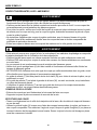
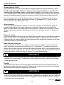
PROPOSITION 65 WARNING: Dust created by power sanding, sawing, grinding, drilling, and other
construction activities may contain chemicals known to the state of California to cause cancer, birth
defects or other reproductive harm. Some examples are:
– Lead from lead-based paints
– Crystalline silica from bricks and cement and other masonry products
– Asbestos dust
– Arsenic and chromium from chemically-treated lumber
• Your risk from these exposures varies depending on how often you do this type of work. To reduce
your exposure to these chemicals: work in a well-ventilated area and work with approved safety
equipment, such as dust masks that are specially designed to lter out microscopic particles.
• Avoid prolonged contact with dust from power sanding, sawing, grinding, drilling, and other
construction activities. Wear protective clothing and wash exposed areas with soap and water.
Allowing dust to get into your mouth, eyes, or lay on the skin may promote absorption of harmful
chemicals.
WARNING
• Use of this tool can generate and/or disburse dust, which may cause serious and permanent
respiratory or other injury. Always use NIOSH/OSHA approved respiratory protection appropriate for
the dust exposure. Direct particles away from face and body. Always operate tool in well-ventilated
area and provide for proper dust removal. Use dust collection system wherever possible.
SAVE THESE INSTRUCTIONS
• Refer to them frequently.
• Use to instruct others who may use the tool.
• If tool is loaned to someone, also loan them these instructions.
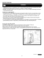
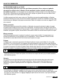
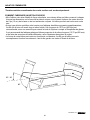
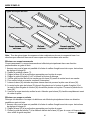
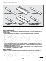
MAKING A PUSH STICK
• In order to operate your table saw safely, you must use a push stick whenever the size or shape of
the workpiece would otherwise cause your hands to be within 6 in. (152 mm) of the saw blade or
other cutter. A push stick is included with this saw.
• No special wood is needed to make additional push-sticks as long as they are sturdy and long
enough. A length of 16 in. (400 mm) is recommended with a notch that ts against the edge of the
workpiece to prevent slipping. It’s a good idea to have several push sticks of the same length
[16 in. (400 mm)] with dierent size notches for dierent workpiece thicknesses.
• The shape can vary to suit your own needs as long as it performs its intended function of keeping
your hands away from the blade. Angling the notch so the push stick can be held at a 20-30 degree
angle from the saw’s table will help you to hold down the workpiece while also moving it through the
saw. See push stick enclosed with your saw.

12
kobalttools.com
POWER CONNECTION
EXTENSION CORDS
WARNING
• Keep the extension cord clear of the working area. Position the cord so it will not get caught on
lumber, tools or other obstructions while you are working with a power tool. Failure to do so can
result in serious personal injury.
• Check extension cords before each use. If damaged, replace immediately. Never use product with a
damaged cord. Touching the damaged area could cause electrical shock resulting in serious injury.
• Use only 3-wire extension cords with 3-prong grounding plugs and 3-pole receptacles that
accept the tool's plug. When using a power tool at a considerable distance from the power source,
use an extension cord heavy enough to carry the current that the tool will draw. An undersized
extension cord will cause a drop in line voltage, resulting in a loss of power and causing the motor
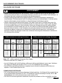
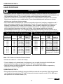
to overheat. Use the chart below to determine the minimum wire size required for an extension cord.
Only round, jacketed cords listed by Underwriter's Laboratories (UL) should be used.
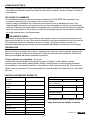
Minimum Gauge Extension Cord
Ampere
Rating Volts
Total Cord
Length
in feet
Gauge of
Extension
Cord
0-6
0-6
0-6
0-6
120
120
120
120
Up to 25
25-50
50-100
100-150
18 AWG
16 AWG
16 AWG
14 AWG
6-10
6-10
6-10
6-10
120
120
120
120
Up to 25
25-50
50-100
100-150
18 AWG
16 AWG
14 AWG
12 AWG
Minimum Gauge Extension Cord
Ampere
Rating Volts
Total Cord
Length
in feet
Gauge of
Extension
Cord
10-12
10-12
10-12
10-12
120
120
120
120
Up to 25
25-50
50-100
100-150
16 AWG
16 AWG
14 AWG
12 AWG
12-16
12-16
12-16
120
120
120
Up to 25
25-50
14 AWG
12 AWG
Greater than 50 feet not
recommended
Note: AWG=American Wire Gauge
*Used on 12 gauge – 20 amp circuit
• When working with the tool outdoors, use an extension cord designed for outside use. This is
indicated by the letters “W-A” or “W” on the cord’s jacket.
• Before using an extension cord, inspect it for loose or exposed wires and cut or worn insulation.
ELECTRICAL CONNECTION
• This product is powered by a precision built electric motor. It should be connected to a power supply
that is 120 V, AC only (normal household current), 60 Hz. DO NOT operate this product on direct
current (DC).
• A substantial voltage drop will cause a loss of power and the motor will overheat.
• If the saw does not operate when plugged into an outlet, double check the power supply.

13
kobalttools.com
POWER CONNECTION
PREPARATION
PRODUCT SPECIFICATIONS
Before beginning assembly of product, make sure all parts are present. Compare parts with package
contents list and hardware contents list. If any part is missing or damaged, DO NOT attempt to
assemble the product.
Estimated Assembly Time: 45 minutes
Tools Required for Assembly (not included): Sharp knife or utility knife to cut carton, Phillips
screwdriver, athead screwdriver, combination square, framing square, tape measure or ruler,
13 mm open end wrench, 10 mm open end wrench or adjustable wrench, 5 mm Allen wrench.
SPEED AND WIRING
• The no-load speed of this tool is approximately 5,000 RPM. This speed is not constant and
decreases under a load or with lower voltage.
• For voltage, the wiring in a shop is as important as the motor’s horsepower rating. A line intended
only for lights cannot properly carry a power tool motor. Wire that is heavy enough for a short
distance will be too light for a greater distance. A line that can support one power tool may not be
able to support two or three tools.
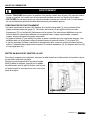
DOUBLE INSULATION
To reduce the risk of electric shock, this equipment has a polarized plug (one blade is wider than the
other). This plug will t in a polarized outlet only one way. If the plug does not t fully in the outlet,
reverse the plug. If it still does not t, contact a qualied electrician to install the proper outlet.
DO NOT change the plug in any way.
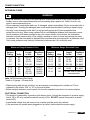
Max depth of cut at 90 degrees 3- 1/2 in
Max depth of cut at 45 degrees 2 - 1/2 in
Max rip to right of blade 30 in
Max rip to left of blade 17 in
Net Weight 68 lbs
Input 120 V~, 60hz, 15 Amps
Blade Arbor Hole 5/8 in
Blade Diameter 10 in
No Load Speed 5,000 r/min (RPM)
Blade Max Speed Rating 5,500 r/min (RPM)
Number of Teeth 28
Blade Thickness 0.07” (1.8 mm)
Blade Kerf 0.1” (2.6mm)
BLADE DESCRIPTIONS
APPLICATION DIAMETER TEETH
Construction Saw Blades (thin kerf with anti-stick rim)
General Purpose 10”(254mm) 28/40
Fine Crosscuts 10”(254mm) 60
Woodworking Saw Blades (provide smooth, clean cuts)
Fine crosscuts 10”(254mm) 80
This tool can only be used with woodworking
saw blades.

14
kobalttools.com
ASSEMBLY INSTRUCTIONS
WARNING
• DO NOT use this product if any parts on the Loose Parts List are already assembled to your product
when you unpack it. Parts on this list are not assembled to the product by the manufacturer and
require customer installation. Use of a product that may have been improperly assembled could
result in serious personal injury.
• If any parts are damaged or missing, DO NOT operate this saw until the parts are replaced. Use of
this product with damaged or missing parts could result in serious personal injury.
• DO NOT attempt to modify this saw or create accessories not recommended for use with this saw.
Any such alteration or modication is misuse and could result in a hazardous condition leading to
possible serious personal injury.
• DO NOT connect to power supply until assembly is complete. Failure to comply could
result in accidental starting and possible serious personal injury.
• DO NOT lift the saw without help. Hold it close to your body. Keep your knees bent and lift with your
legs, not your back. Ignoring these precautions can result in back injury.
• NEVER stand directly in line with the blade or allow hands to come closer than 6 in. to the blade.
DO NOT reach over or across the blade. Failure to heed this warning can result in serious personal
injury.
• FULLY ASSEMBLE saw with leg assembly prior to use. Leg assembly is an integral and necessary
part of the support structure for this saw.
This product requires assembly.
• Carefully remove the upper piece of packaging material and leave the saw in the lower piece of
packaging material.
• This tool is heavy. To avoid back injury, keep your knees bent and lift with your legs, not your back.
Get help when needed.
• Inspect the tool carefully to make sure no breakage or damage occurred during shipping.
• DO NOT discard the packaging material until you have carefully inspected the tool, identied all
loose parts, and satisfactorily operated the tool.
• The saw is factory set for accurate cutting. After assembling it, check for accuracy. If shipping has
inuenced the settings, refer to specic procedures explained in this manual.
• If any parts are damaged or missing, please call 1-888-356-2258 for assistance.

15
kobalttools.com
ASSEMBLY INSTRUCTIONS
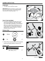
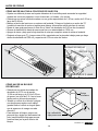
TABLE STAND ASSEMBLY
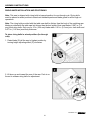
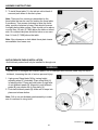
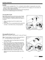
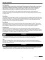
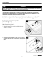
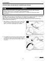
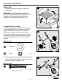
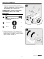
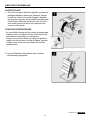
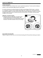
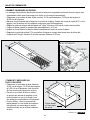
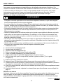
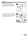
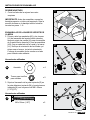
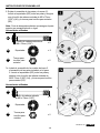
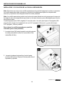
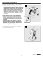
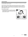
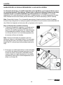
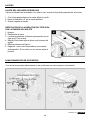
2. First remove washers (KK) and nuts (JJ) from
lower right leg assembly, then attach wheels
(K) to lower right leg assembly (J) with washers
(KK) (one on each side of wheel) and nut (JJ).
Check orientation of wheels and if wheels rub
against frame, reverse orientation. Set wheel
assembly aside for later use.
UNPACKING
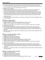
1. Cut sides of box at all four corners.
IMPORTANT: Before assembly, separate upper
and lower packing trays. Leave base section in
lower tray while completing steps 1 - 8.
1
1
2
3
CC
M
N
R
2
J
KK
JJ
KK
K
1
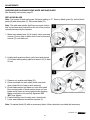
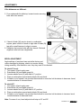
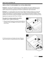
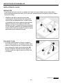
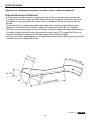
3. Attach left leg cross piece (R) to left front leg (M)
and left rear leg (N) with M6 x 50 bolts (CC).
Hardware Used
M6 x 50mm (1.97")
x 2
CC
2 in. Bolt
Qty. 2
Nut
(preassembled
to lower right
leg assembly)
Qty. 2
Washer
(preassembled
to lower right
leg assembly)
Qty. 4
3 in. Cap screw
Qty. 6
Height adjustment
knob
Qty. 1
8 mm Hex bolt
Qty. 1
1-1/2 in. Cap screw
Qty. 4
Spacer
Qty. 6
Nut
Qty. 10
1 in. hex bolt
Qty. 2
AA BB CC
DD
EE
JJ
KK
FF GG
HH
Hardware Used
Nut
x 2
JJ
2 in. Bolt
Qty. 2
Nut
(preassembled
to lower right
leg assembly)
Qty. 2
Washer
(preassembled
to lower right
leg assembly)
Qty. 4
3 in. Cap screw
Qty. 6
Height adjustment
knob
Qty. 1
8 mm Hex bolt
Qty. 1
1-1/2 in. Cap screw
Qty. 4
Spacer
Qty. 6
Nut
Qty. 10
1 in. hex bolt
Qty. 2
AA BB CC
DD
EE
JJ
KK
FF GG
HH
Washer
x 4
KK
2 in. Bolt
Qty. 2
Nut
(preassembled
to lower right
leg assembly)
Qty. 2
Washer
(preassembled
to lower right
leg assembly)
Qty. 4
3 in. Cap screw
Qty. 6
Height adjustment
knob
Qty. 1
8 mm Hex bolt
Qty. 1
1-1/2 in. Cap screw
Qty. 4
Spacer
Qty. 6
Nut
Qty. 10
1 in. hex bolt
Qty. 2
AA BB CC
DD
EE
JJ
KK
FF GG
HH

16
kobalttools.com
ASSEMBLY INSTRUCTIONSASSEMBLY INSTRUCTIONS
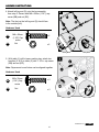
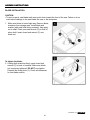
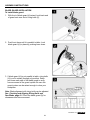
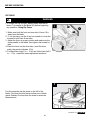
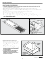
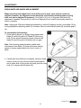
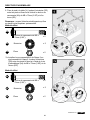
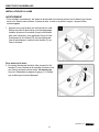
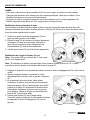
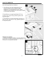
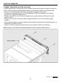
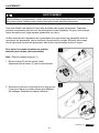
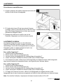
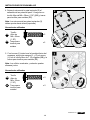
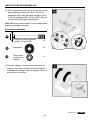
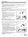
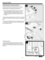
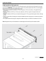
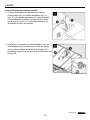
5. With table (V) still in lower packing tray, attach two
handles (I1 & I2) to table (V) with 1-1/2 in. cap screw
(BB) and nut (EE).
Note: Square and round holes can be aligned together.
4. Attach left leg end (S) onto the leg assembly
from step 3. Secure with M8 x 35mm (1.38"). cap
screw (BB) and nut (EE).
Note: The feet on the left leg end (S) should face
to the outside (left).
1
1
3
2
2
4
BB
EE
N
M
S
Hardware Used
x 2
BB
2 in. Bolt
Qty. 2
Nut
(preassembled
to lower right
leg assembly)
Qty. 2
Washer
(preassembled
to lower right
leg assembly)
Qty. 4
3 in. Cap screw
Qty. 6
Height adjustment
knob
Qty. 1
8 mm Hex bolt
Qty. 1
1-1/2 in. Cap screw
Qty. 4
Spacer
Qty. 6
Nut
Qty. 10
1 in. hex bolt
Qty. 2
AA BB CC
DD
EE
JJ
KK
FF GG
HH
M8 x 35mm
(1.38") Cap
screw
Nut
x 2
EE
2 in. Bolt
Qty. 2
Nut
(preassembled
to lower right
leg assembly)
Qty. 2
Washer
(preassembled
to lower right
leg assembly)
Qty. 4
3 in. Cap screw
Qty. 6
Height adjustment
knob
Qty. 1
8 mm Hex bolt
Qty. 1
1-1/2 in. Cap screw
Qty. 4
Spacer
Qty. 6
Nut
Qty. 10
1 in. hex bolt
Qty. 2
AA BB CC
DD
EE
JJ
KK
FF GG
HH
Hardware Used
x 2
BB
Nut
x 2
EE
2 in. Bolt
Qty. 2
Nut
(preassembled
to lower right
leg assembly)
Qty. 2
Washer
(preassembled
to lower right
leg assembly)
Qty. 4
3 in. Cap screw
Qty. 6
Height adjustment
knob
Qty. 1
8 mm Hex bolt
Qty. 1
1-1/2 in. Cap screw
Qty. 4
Spacer
Qty. 6
Nut
Qty. 10
1 in. hex bolt
Qty. 2
AA BB CC
DD
EE
JJ
KK
FF GG
HH
M8 x 35mm
(1.38") Cap
screw

17
kobalttools.com
ASSEMBLY INSTRUCTIONS
Hardware Used
Hardware Used
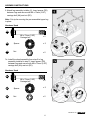
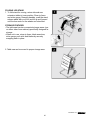
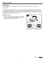
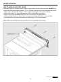
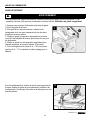
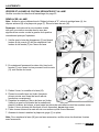
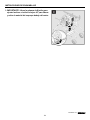
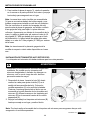
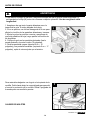
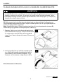
6. Attach leg assembly to table (V). Insert spacer (DD)
between legs and secure with M8 x 75mm (2.95")
carriage bolt (AA) and nut (EE).
Note: Cut zip tie securing the pre-assembled upper leg
in place.
Nut
Nut
x 2
x 2
EE
EE
2 in. Bolt
Qty. 2
Nut
(preassembled
to lower right
leg assembly)
Qty. 2
Washer
(preassembled
to lower right
leg assembly)
Qty. 4
3 in. Cap screw
Qty. 6
Height adjustment
knob
Qty. 1
8 mm Hex bolt
Qty. 1
1-1/2 in. Cap screw
Qty. 4
Spacer
Qty. 6
Nut
Qty. 10
1 in. hex bolt
Qty. 2
AA BB CC
DD
EE
JJ
KK
FF GG
HH
Spacer
Spacer
x 2
x 2
DD
DD
2 in. Bolt
Qty. 2
Nut
(preassembled
to lower right
leg assembly)
Qty. 2
Washer
(preassembled
to lower right
leg assembly)
Qty. 4
3 in. Cap screw
Qty. 6
Height adjustment
knob
Qty. 1
8 mm Hex bolt
Qty. 1
1-1/2 in. Cap screw
Qty. 4
Spacer
Qty. 6
Nut
Qty. 10
1 in. hex bolt
Qty. 2
AA BB CC
DD
EE
JJ
KK
FF GG
HH
x 2
x 2
AA
AA
2 in. Bolt
Qty. 2
Nut
(preassembled
to lower right
leg assembly)
Qty. 2
Washer
(preassembled
to lower right
leg assembly)
Qty. 4
3 in. Cap screw
Qty. 6
Height adjustment
knob
Qty. 1
8 mm Hex bolt
Qty. 1
1-1/2 in. Cap screw
Qty. 4
Spacer
Qty. 6
Nut
Qty. 10
1 in. hex bolt
Qty. 2
AA BB CC
DD
EE
JJ
KK
FF GG
HH
M8 x 75mm (2.95")
Carriage bolt
M8 x 75mm (2.95")
Carriage bolt
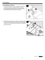
7a. Install the wheel assembly from step 2 to leg
assembly installed in step 6. Insert spacer (DD)
between legs and secure with M8 x 75mm (2.95")
carriage bolt (AA) and nut (EE).
2 in. Bolt
Qty. 2
Nut
(preassembled
to lower right
leg assembly)
Qty. 2
Washer
(preassembled
to lower right
leg assembly)
Qty. 4
3 in. Cap screw
Qty. 6
Height adjustment
knob
Qty. 1
8 mm Hex bolt
Qty. 1
1-1/2 in. Cap screw
Qty. 4
Spacer
Qty. 6
Nut
Qty. 10
1 in. hex bolt
Qty. 2
AA BB CC
DD
EE
JJ
KK
FF GG
HH

18
kobalttools.com
ASSEMBLY INSTRUCTIONS
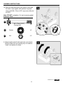
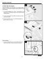
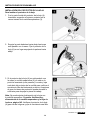
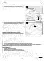
7b. Raise the narrowest part of the stand to help align
the holes. Insert spacer (DD) between legs and
secure with M8 x 75mm (2.95") cap screw (AA) and
nut (EE).
Note: DO NOT overtighten. Cut zip tie securing pedal.
Nut
x 2
EE
2 in. Bolt
Qty. 2
Nut
(preassembled
to lower right
leg assembly)
Qty. 2
Washer
(preassembled
to lower right
leg assembly)
Qty. 4
3 in. Cap screw
Qty. 6
Height adjustment
knob
Qty. 1
8 mm Hex bolt
Qty. 1
1-1/2 in. Cap screw
Qty. 4
Spacer
Qty. 6
Nut
Qty. 10
1 in. hex bolt
Qty. 2
AA BB CC
DD
EE
JJ
KK
FF GG
HH
Spacer
x 2
DD
2 in. Bolt
Qty. 2
Nut
(preassembled
to lower right
leg assembly)
Qty. 2
Washer
(preassembled
to lower right
leg assembly)
Qty. 4
3 in. Cap screw
Qty. 6
Height adjustment
knob
Qty. 1
8 mm Hex bolt
Qty. 1
1-1/2 in. Cap screw
Qty. 4
Spacer
Qty. 6
Nut
Qty. 10
1 in. hex bolt
Qty. 2
AA BB CC
DD
EE
JJ
KK
FF GG
HH
x 2
AA
2 in. Bolt
Qty. 2
Nut
(preassembled
to lower right
leg assembly)
Qty. 2
Washer
(preassembled
to lower right
leg assembly)
Qty. 4
3 in. Cap screw
Qty. 6
Height adjustment
knob
Qty. 1
8 mm Hex bolt
Qty. 1
1-1/2 in. Cap screw
Qty. 4
Spacer
Qty. 6
Nut
Qty. 10
1 in. hex bolt
Qty. 2
AA BB CC
DD
EE
JJ
KK
FF GG
HH
M8 x 75mm (2.95")
Carriage bolt
Hardware Used
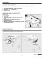
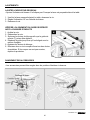
8. Grasp handles and tilt table saw back onto wheels.
Remove table saw from packing tray. Let machine
"stand" and tighten all screws.

19
ASSEMBLY INSTRUCTIONS
kobalttools.com
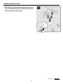
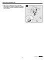
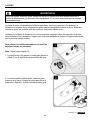
9. IMPORTANT: Release height adjustment locking
lever and tilt blade to 45˚ to release and remove
packing material under motor.

20
ASSEMBLY INSTRUCTIONS
Hardware Used
kobalttools.com
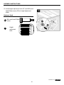
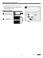
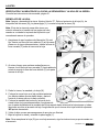
10. Install height adjustment knob (FF) and M8 round
head Philips screw (GG) to height adjustment
wheel.
GG
2 in. Bolt
Qty. 2
Nut
(preassembled
to lower right
leg assembly)
Qty. 2
Washer
(preassembled
to lower right
leg assembly)
Qty. 4
3 in. Cap screw
Qty. 6
Height adjustment
knob
Qty. 1
8 mm Hex bolt
Qty. 1
1-1/2 in. Cap screw
Qty. 4
Spacer
Qty. 6
Nut
Qty. 10
1 in. hex bolt
Qty. 2
AA BB CC
DD
EE
JJ
KK
FF GG
HH
M8 round head Philips
screw
Height
adjustment
knob
FF
2 in. Bolt
Qty. 2
Nut
(preassembled
to lower right
leg assembly)
Qty. 2
Washer
(preassembled
to lower right
leg assembly)
Qty. 4
3 in. Cap screw
Qty. 6
Height adjustment
knob
Qty. 1
8 mm Hex bolt
Qty. 1
1-1/2 in. Cap screw
Qty. 4
Spacer
Qty. 6
Nut
Qty. 10
1 in. hex bolt
Qty. 2
AA BB CC
DD
EE
JJ
KK
FF GG
HH
La page est en cours de chargement...
La page est en cours de chargement...
La page est en cours de chargement...
La page est en cours de chargement...
La page est en cours de chargement...
La page est en cours de chargement...
La page est en cours de chargement...
La page est en cours de chargement...
La page est en cours de chargement...
La page est en cours de chargement...
La page est en cours de chargement...
La page est en cours de chargement...
La page est en cours de chargement...
La page est en cours de chargement...
La page est en cours de chargement...
La page est en cours de chargement...
La page est en cours de chargement...
La page est en cours de chargement...
La page est en cours de chargement...
La page est en cours de chargement...
La page est en cours de chargement...
La page est en cours de chargement...
La page est en cours de chargement...
La page est en cours de chargement...
La page est en cours de chargement...
La page est en cours de chargement...
La page est en cours de chargement...
La page est en cours de chargement...
La page est en cours de chargement...
La page est en cours de chargement...
La page est en cours de chargement...
La page est en cours de chargement...
La page est en cours de chargement...
La page est en cours de chargement...
La page est en cours de chargement...
La page est en cours de chargement...
La page est en cours de chargement...
La page est en cours de chargement...
La page est en cours de chargement...
La page est en cours de chargement...
La page est en cours de chargement...
La page est en cours de chargement...
La page est en cours de chargement...
La page est en cours de chargement...
La page est en cours de chargement...
La page est en cours de chargement...
La page est en cours de chargement...
La page est en cours de chargement...
La page est en cours de chargement...
La page est en cours de chargement...
La page est en cours de chargement...
La page est en cours de chargement...
La page est en cours de chargement...
La page est en cours de chargement...
La page est en cours de chargement...
La page est en cours de chargement...
La page est en cours de chargement...
La page est en cours de chargement...
La page est en cours de chargement...
La page est en cours de chargement...
La page est en cours de chargement...
La page est en cours de chargement...
La page est en cours de chargement...
La page est en cours de chargement...
La page est en cours de chargement...
La page est en cours de chargement...
La page est en cours de chargement...
La page est en cours de chargement...
La page est en cours de chargement...
La page est en cours de chargement...
La page est en cours de chargement...
La page est en cours de chargement...
La page est en cours de chargement...
La page est en cours de chargement...
La page est en cours de chargement...
La page est en cours de chargement...
La page est en cours de chargement...
La page est en cours de chargement...
La page est en cours de chargement...
La page est en cours de chargement...
La page est en cours de chargement...
La page est en cours de chargement...
La page est en cours de chargement...
La page est en cours de chargement...
La page est en cours de chargement...
La page est en cours de chargement...
La page est en cours de chargement...
La page est en cours de chargement...
La page est en cours de chargement...
La page est en cours de chargement...
La page est en cours de chargement...
La page est en cours de chargement...
La page est en cours de chargement...
La page est en cours de chargement...
La page est en cours de chargement...
La page est en cours de chargement...
La page est en cours de chargement...
La page est en cours de chargement...
La page est en cours de chargement...
La page est en cours de chargement...
La page est en cours de chargement...
La page est en cours de chargement...
La page est en cours de chargement...
La page est en cours de chargement...
La page est en cours de chargement...
La page est en cours de chargement...
La page est en cours de chargement...
La page est en cours de chargement...
La page est en cours de chargement...
La page est en cours de chargement...
La page est en cours de chargement...
La page est en cours de chargement...
La page est en cours de chargement...
La page est en cours de chargement...
La page est en cours de chargement...
La page est en cours de chargement...
La page est en cours de chargement...
La page est en cours de chargement...
La page est en cours de chargement...
La page est en cours de chargement...
La page est en cours de chargement...
La page est en cours de chargement...
La page est en cours de chargement...
La page est en cours de chargement...
La page est en cours de chargement...
La page est en cours de chargement...
La page est en cours de chargement...
La page est en cours de chargement...
La page est en cours de chargement...
La page est en cours de chargement...
La page est en cours de chargement...
La page est en cours de chargement...
-
 1
1
-
 2
2
-
 3
3
-
 4
4
-
 5
5
-
 6
6
-
 7
7
-
 8
8
-
 9
9
-
 10
10
-
 11
11
-
 12
12
-
 13
13
-
 14
14
-
 15
15
-
 16
16
-
 17
17
-
 18
18
-
 19
19
-
 20
20
-
 21
21
-
 22
22
-
 23
23
-
 24
24
-
 25
25
-
 26
26
-
 27
27
-
 28
28
-
 29
29
-
 30
30
-
 31
31
-
 32
32
-
 33
33
-
 34
34
-
 35
35
-
 36
36
-
 37
37
-
 38
38
-
 39
39
-
 40
40
-
 41
41
-
 42
42
-
 43
43
-
 44
44
-
 45
45
-
 46
46
-
 47
47
-
 48
48
-
 49
49
-
 50
50
-
 51
51
-
 52
52
-
 53
53
-
 54
54
-
 55
55
-
 56
56
-
 57
57
-
 58
58
-
 59
59
-
 60
60
-
 61
61
-
 62
62
-
 63
63
-
 64
64
-
 65
65
-
 66
66
-
 67
67
-
 68
68
-
 69
69
-
 70
70
-
 71
71
-
 72
72
-
 73
73
-
 74
74
-
 75
75
-
 76
76
-
 77
77
-
 78
78
-
 79
79
-
 80
80
-
 81
81
-
 82
82
-
 83
83
-
 84
84
-
 85
85
-
 86
86
-
 87
87
-
 88
88
-
 89
89
-
 90
90
-
 91
91
-
 92
92
-
 93
93
-
 94
94
-
 95
95
-
 96
96
-
 97
97
-
 98
98
-
 99
99
-
 100
100
-
 101
101
-
 102
102
-
 103
103
-
 104
104
-
 105
105
-
 106
106
-
 107
107
-
 108
108
-
 109
109
-
 110
110
-
 111
111
-
 112
112
-
 113
113
-
 114
114
-
 115
115
-
 116
116
-
 117
117
-
 118
118
-
 119
119
-
 120
120
-
 121
121
-
 122
122
-
 123
123
-
 124
124
-
 125
125
-
 126
126
-
 127
127
-
 128
128
-
 129
129
-
 130
130
-
 131
131
-
 132
132
-
 133
133
-
 134
134
-
 135
135
-
 136
136
-
 137
137
-
 138
138
-
 139
139
-
 140
140
-
 141
141
-
 142
142
-
 143
143
-
 144
144
-
 145
145
-
 146
146
-
 147
147
-
 148
148
-
 149
149
-
 150
150
-
 151
151
-
 152
152


Kobalt KT10152 Manuel utilisateur
- Catégorie
- Outils électroportatifs
- Taper
- Manuel utilisateur
dans d''autres langues
- English: Kobalt KT10152 User manual
- español: Kobalt KT10152 Manual de usuario
Documents connexes
Autres documents
-
Hitachi C 6U2 Manuel utilisateur
-
Delta 36-6013 Le manuel du propriétaire
-
-
-
-
Delta 36-5000T2 Manuel utilisateur
-
-
Delta 36-5000 Le manuel du propriétaire
-
-