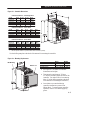
Allen-Bradley 160 SSC Guide d'installation
- Taper
- Guide d'installation

160 SSC™
Variable
Speed
Controller
(Series B)
0.37 – 2.2 kW (1/2 – 3 HP)
FRN 5.xx
Allen-Bradley
Installation
Manual
Table of Contents Index
spl_en_b.fm5 Page 1 Monday, September 15, 1997 1:31 PM

This
manual is intended to
guide qualified
personnel in the installation and operation of this
product.
Because of the variety of uses for this equipment
and because of the dif
ferences between this
solid-state equipment and electromechanical
equipment, the user of and those responsible for
applying this equipment must satisfy themselves
as to the acceptability of each application and use
of the equipment. In no event will Rockwell
Automation Company be responsible or liable for
indirect or consequential damages resulting from
the use or application of this equipment.
The illustrations shown in this manual are
intended solely to illustrate the text of this
manual. Because of the many variables and
requirements associated with any particular
installation, Rockwell Automation cannot assume
responsibility or liability for actual use based
upon the illustrative uses and applications.
No patent liability is assumed by Rockwell
Automation with respect to use of information,
circuits or equipment described in this text.
Reproduction of the content of this manual, in
whole or in part, without written permission of
the Rockwell Automation Company is prohibited.
The information in this manual is or
ganized in
numbered chapters. Read each chapter in
sequence and perform procedures when you are
instructed to do so. Do not proceed to the next
chapter until you have completed all procedures.
Throughout this manual we use notes to make you
aware of safety considerations:
A
TTENTION:
Identifies information
about practices or circumstances that
can lead to personal injury or death,
property damage or economic loss.
Attentions help you:
D identify a hazard
D avoid the hazard
D
recognize the consequences
Important: Identifies information that is
especially important for successful application
and understanding of the product.

160_5_9DU3.doc 1 Mon Sep 15 11:46:33 1997
This publication provides new information for the 160 SSC Variable
Speed Controller User Manual, publication 160-5.9, dated
December, 1996. Please place this document in your manual for
future reference.
Important Note Bulletin 160 SSC Controllers with a catalog number suffix of “S01,”
(i.e. 160S-AA02NS01) will have the “Motor Stall Fault” (F06, page
6-2) detection feature disabled. All other features specified in the
User Manual will be operational.
Document Update
160 SSC™ Variable Speed
Controller (Series B)
Rockwell Automation helps its customers receive a superior return on their investment by bringing
together leading brands in industrial automation, creating a broad spectrum of easy-to-integrate
products. These are supported by local technical resources available worldwide, a global network
of system solutions providers, and the advanced technology resources of Rockwell.
Worldwide representation.
Argentina • Australia • Austria • Bahrain • Belgium • Bolivia • Brazil • Bulgaria • Canada • Chile • China, People’s Republic of • Colombia • Costa Rica • Croatia • Cyprus
Czech Republic • Denmark • Dominican Republic • Ecuador • Egypt • El Salvador • Finland • France • Germany • Ghana • Greece • Guatemala • Honduras • Hong Kong
Hungary • Iceland • India • Indonesia • Iran • Ireland • Israel • Italy • Jamaica • Japan • Jordan • Korea • Kuwait • Lebanon • Macau • Malaysia • Malta • Mexico
Morocco • The Netherlands • New Zealand • Nigeria • Norway • Oman • Pakistan • Panama • Peru • Philippines • Poland • Portugal • Puerto Rico • Qatar • Romania • Russia
Saudi Arabia • Singapore • Slovakia • Slovenia • South Africa, Republic of • Spain • Sweden • Switzerland • Taiwan • Thailand • Trinidad • Tunisia • Turkey • United Arab Emirates
United Kingdom • United States • Uruguay • Venezuela
Rockwell Automation Headquarters, 1201 South Second Street, Milwaukee, WI 53204-2496 USA, Tel: (1) 414 382-2000, Fax: (1) 414 382-4444
Publication 160-5.9DU3 – April, 1997 P/N 40055-188-01 (A)
Copyright 1997 Rockwell International Corporation. All rights reserved. Printed in USA.
SSC is a trademark of Rockwell Automation.

160_5_9DU2.doc 1 Mon Sep 15 11:42:00 1997
This publication provides new and updated material for the 160 SSC
Variable Speed Controller User Manual, publication 160-5.9, dated
December, 1996. Please place this document in your manual for
future reference.
EMC Directive 89/336/EEC This controller is a component intended for implementation in
machines or systems for the industrial environment. It has been tested
to meet the Council Directive 89/336 Electromagnetic Compatibility
(EMC) and all applicable standards.
Important: The conformity of the controller and filter to any standard
does not guarantee that the entire installation will con-
form. Many other factors can influence the total installa-
tion and only direct measurements can verify total con-
formity. It is therefore the responsibility of the machine
manufacturer, to ensure, that the conformity is met.
Essential Requirements for a Conforming EMC Installation
1. An input line filter module (see “Accessories” in Appendix A)
must be installed to reduce conducted emissions. When using the
filters listed in Appendix A, the maximum motor cable lengths
must be 75 meters (250 feet) for controllers rated 200-240VAC,
and 40 meters (133 feet) for controllers rated 380-460VAC.
2. The controller system must be mounted in a shielded enclosure
to reduce radiated emissions.
3. Grounding of equipment and cable shields must be solid, with
low impedance connections.
4. Motor and control cables entering the shielded enclosure must
have EMC-tested shielded cable clamps, or grounded metal
conduit.
5. All motor cables must use shielded cable, or be in grounded metal
conduit.
6. All control and signal wiring must use shielded cable or be in
grounded metal conduit.
7. The Common terminals (TB3-3 & 7) must have a solid connection
to PE (protective earth).
Document Update
160 SSC™ Variable Speed
Controller (Series B)
SSC is a trademark of Rockwell Automation.

160_5_9DU2.doc 2 Mon Sep 15 11:42:00 1997
2 160 SSC™ Variable Speed Controller (Series B)
General Instructions for an
EMC Compliant Installation
Refer to Figure 1.
Shielded Enclosure
• Typical NEMA or IEC metal enclosures are adequate.
• The ground connection of the shielded enclosure must be solidly
connected to the PE terminal of the controller. Good conductivity
must be assured – grounding must provide a low impedance path
to high frequency signals.
• All wiring, except input power leads, must use shielded cable.
• Input power, output power and control wiring inside the enclosure
must be physically separated.
• Input power, output power and control wiring outside the enclosure
must use separate shielded cables, or separate conduit.
Cable Clamps
• Use suitable EMC-tested cable clamps only.
• The connection area must be 360 degrees around the shielded cable.
• The cable clamps also provide strain-relief for the cable.
• When using conduit, the contact point of metal entry connections
must be free of paint or non-conductive surfaces and solidly
connected with good conductivity to the enclosure.
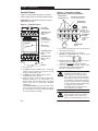
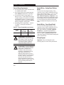
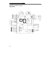
Figure 1 Recommended Grounding Configuration
R (L1)
S (L2)
T (L3)
PE
AC
Input Line
Shielded Enclosure
Enclosure Ground Connection
U (T1)
Shielded Motor Cable
to TB3
Control
Cabinet
*
to Motor
V (T2)
W (T3)
R (L1)
S (L2)
T (L3)
= EMC Tested Shielded Cable Clamp (or Metal Conduit)
* When the control circuitry is located outside of the 160 enclosure.
Control Wiring TB3
Motor Wiring TB2
L2
S
L1
R
L3
T
BR
–
BR
+
1 2 3 4 5 6 7 8 9 10 11
T2
V
TI
U
T3
W
–
DC
+
DC
Ground Tab – PE
Line Power TB1
FAULT
READY
Line
Filter

160_5_9DU2.doc 3 Mon Sep 15 11:42:00 1997
160 SSC™ Variable Speed Controller (Series B) 3
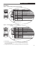
Motor Cable
• The cable between the controller and motor must be a 4-wire
shielded cable (three phases and ground). Refer to Figures 2 & 3.
• When using a line filter module as specified in Appendix A, motor
cable lengths shall be limited to 75 meters (250 feet) for controllers
rated 200-240VAC and 40 meters (133 feet) for controllers rated
380-460VAC.
• Inside the shielded enclosure, shielded motor cable must be used
as close to the controller’s output terminals as possible. The shield
must be solidly connected to the PE terminal of the controller.
• Where the shielded motor cable exits the enclosure, an EMC-tested
cable clamp, or metal conduit must be used to solidly connect the
cable shield to the enclosure.
• The shield on the motor side must be solidly connected to the motor
housing with an EMC-tested cable clamp, or conduit, providing
good conductivity from the cable shield to the motor housing.
Figure 2 Motor Connections
Figure 3 Shielded Motor and Control Cable Example
Shielded Enclosure
U (T1)
V (T2)
W (T3)
= EMC Tested Shielded Cable Clamp (or Metal Conduit)
* When the control circuitry is located outside of the 160 enclosure.
Motor Wiring TB2
L2
S
L1
R
L3
T
BR
–
BR
+
1 2 3 4 5 6 7 8 9 10 11
T2
V
TI
U
T3
W
–
DC
+
DC
Ground Tab – PE
FAULT
READY
4 Wire
Shielded Motor Cable
Ground to Motor Housing
Stranded Copper Wire
Plastic Insulation
Inner Plastic Sheath
Compact Screen of Galvanized (Tinned) Copper or Steel
Outer Plastic Jacket

160_5_9DU2.doc 4 Mon Sep 15 11:42:00 1997
4 160 SSC™ Variable Speed Controller (Series B)
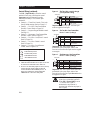
Control Cable
• Control wiring must use shielded cable, or grounded metal conduit.
Refer Figures 3 and 4.
• The shield must be connected to signal common at both ends of
the cable.
• The Common terminals (TB3-3 & 7) must be solidly connected
(and as short as possible) to the PE terminal of the controller.
Figure 4 Control Connections
Shielded Enclosure
= EMC Tested Shielded Cable Clamp (or Metal Conduit)
* When the control circuitry is located outside of the 160 enclosure.
Control Wiring TB3
L2
S
L1
R
L3
T
BR
–
BR
+
1 2 4 5 6 8 9 10 11
T2
V
TI
U
T3
W
–
DC
+
DC
Ground Tab – PE
FAULT
READY
Shielded Control
Cable
Signal
Common
Control
Cabinet
*
to TB3
3 7
Rockwell Automation helps its customers receive a superior return on their investment by bringing
together leading brands in industrial automation, creating a broad spectrum of easy-to-integrate
products. These are supported by local technical resources available worldwide, a global network
of system solutions providers, and the advanced technology resources of Rockwell.
Worldwide representation.
Argentina • Australia • Austria • Bahrain • Belgium • Bolivia • Brazil • Bulgaria • Canada • Chile • China, People’s Republic of • Colombia • Costa Rica • Croatia • Cyprus
Czech Republic • Denmark • Dominican Republic • Ecuador • Egypt • El Salvador • Finland • France • Germany • Ghana • Greece • Guatemala • Honduras • Hong Kong
Hungary • Iceland • India • Indonesia • Iran • Ireland • Israel • Italy • Jamaica • Japan • Jordan • Korea • Kuwait • Lebanon • Macau • Malaysia • Malta • Mexico
Morocco • The Netherlands • New Zealand • Nigeria • Norway • Oman • Pakistan • Panama • Peru • Philippines • Poland • Portugal • Puerto Rico • Qatar • Romania • Russia
Saudi Arabia • Singapore • Slovakia • Slovenia • South Africa, Republic of • Spain • Sweden • Switzerland • Taiwan • Thailand • Trinidad • Tunisia • Turkey • United Arab Emirates
United Kingdom • United States • Uruguay • Venezuela
Rockwell Automation Headquarters, 1201 South Second Street, Milwaukee, WI 53204-2496 USA, Tel: (1) 414 382-2000, Fax: (1) 414 382-4444
Publication 160-5.9DU2 – May 1997
Copyright 1997 Rockwell International Corporation. All rights reserved. Printed in USA.

t
New features include:
D Incr
eased Low Speed T
orque.
The parameter P71 – [IR Compensation]
was
added, allowing adjustment of the amount of
IR compensation desired. This is used to
compensate for stator resistance and allows
much higher levels of starting torque. The
default level of P38 – [Boost Select]
has
changed.
D Improved Acceleration.
The acceleration current ramp regulator has
been retuned and the current feedback filter
time constant was reduced, allowing improved
performance with short acceleration times
under all load conditions. The drive power-up
diagnostics were also shortened considerably
,
which improves response time to a START
signal.
D Improved Current Sensing
The current sense accuracy has been improved
for low speeds and light loads. Capacitive
current cancellation has been added to
eliminate errors due to long shielded cables.
D Robust Current Limit.
A fast frequency foldback was added to
operate with the hardware current limit. This
allows the drive to continue operating under
adverse conditions.
D Improved Speed Regulation.
The parameter P72 – [Slip Compensation]
was added, which compensates for inherent
slip in an induction motor
. This assists in
maintaining a constant motor shaft speed
under heavy loading conditions.
D Configurable Terminal Block Input
The parameter P46 – [Input Mode]
has been
expanded to provide greater flexibility
. New
input modes include the ability to select
secondary accel/decel times, switch between
local and remote control or enable/disable of
the controller.
D Improved Drive Functionality.
The “DC Injection Braking” setting for P34 –
[Stop Mode Select] has been improved by
incorporating a current limit function. In
addition, the delay time before applying
voltage has been eliminated.
The parameter P44 – [DC Hold Time]
is now
settable up to 25 seconds in 0.1 second
increments and
P37 – [Maximum Voltage]
is
now settable to 1
10% of the drive rating.
D Improved Analog Input Operation.
The input range and scaling of the analog
inputs has been improved. Refer to P60 –
[Zero Offset], P74 – [Analog Select],
P75 – [Analog Input Minimum]
, and
P76 – [Analog Input Maximum].
D Enhanced Frequency Selection.
P58 – [Internal Frequency] is now controlled
in real time. This means that the output
frequency will change while the parameter is
being adjusted. Pressing the ENTER key will
retain the new frequency
. Pressing the ESCape
key will cause the drive to accel/decel back to
the previous setting.
In addition, P58 – [Internal Frequency]
and
P59 – [Frequency Select] are now available
in both the Preset Speed model and the
Analog Signal Follower model.

ii
This Page Intentionally Blank

##"
i
#!!#!$#"
General Information 1–1. . . . . . . . . . . . . . . . . . . . . . . . . . . . . . . . . . . . . . . . . . . . . . . . . . .
Conventions Used In This Manual
1–2. . . . . . . . . . . . . . . . . . . . . . . . . . . . . . . . . . . . . . . .
#!"##!
Installation and Storage 2–1. . . . . . . . . . . . . . . . . . . . . . . . . . . . . . . . . . . . . . . . . . . . . . . . .
EMC Directive Compliance
2–1. . . . . . . . . . . . . . . . . . . . . . . . . . . . . . . . . . . . . . . . . . . . .
Low Voltage Directive Compliance 2–1. . . . . . . . . . . . . . . . . . . . . . . . . . . . . . . . . . . . . . .
Controller Features 2–2. . . . . . . . . . . . . . . . . . . . . . . . . . . . . . . . . . . . . . . . . . . . . . . . . . . .
Power Wiring For Preset Speed and Analog Signal Follower Models 2–2. . . . . . . . . . . . .
Line Side Protection Recommendations 2–3. . . . . . . . . . . . . . . . . . . . . . . . . . . . . . . . . . . .
Motor Cable Recommendations
2–4. . . . . . . . . . . . . . . . . . . . . . . . . . . . . . . . . . . . . . . . . .
Control Wiring Requirements 2–6. . . . . . . . . . . . . . . . . . . . . . . . . . . . . . . . . . . . . . . . . . . .
Control Wiring – Analog Signal Follower Model 2–7. . . . . . . . . . . . . . . . . . . . . . . . . . . .
Control Wiring – Preset Speed Model 2–7. . . . . . . . . . . . . . . . . . . . . . . . . . . . . . . . . . . . .
Control Wiring Diagrams 2–8. . . . . . . . . . . . . . . . . . . . . . . . . . . . . . . . . . . . . . . . . . . . . . .
#!!!& $
Features 3–1. . . . . . . . . . . . . . . . . . . . . . . . . . . . . . . . . . . . . . . . . . . . . . . . . . . . . . . . . . . . .
Display Mode
3–1. . . . . . . . . . . . . . . . . . . . . . . . . . . . . . . . . . . . . . . . . . . . . . . . . . . . . . . .
Program Mode 3–1. . . . . . . . . . . . . . . . . . . . . . . . . . . . . . . . . . . . . . . . . . . . . . . . . . . . . . . .
Removing Program Keypad Module 3–2. . . . . . . . . . . . . . . . . . . . . . . . . . . . . . . . . . . . . .
#!#!#
Start–up Procedure (Analog Signal Follower Model) 4–1. . . . . . . . . . . . . . . . . . . . . . . . .
Start–up Procedure (Preset Speed Model) 4–1. . . . . . . . . . . . . . . . . . . . . . . . . . . . . . . . . .
#!!#!"!!
Overview of Parameters 5–1. . . . . . . . . . . . . . . . . . . . . . . . . . . . . . . . . . . . . . . . . . . . . . . .
Programming Example 5–1. . . . . . . . . . . . . . . . . . . . . . . . . . . . . . . . . . . . . . . . . . . . . . . . .
Display Group Parameters 5–2. . . . . . . . . . . . . . . . . . . . . . . . . . . . . . . . . . . . . . . . . . . . . .
Program Group Parameters 5–4. . . . . . . . . . . . . . . . . . . . . . . . . . . . . . . . . . . . . . . . . . . . . .
#!!$"#$#!#
Fault Information 6–1. . . . . . . . . . . . . . . . . . . . . . . . . . . . . . . . . . . . . . . . . . . . . . . . . . . . .
Troubleshooting 6–3. . . . . . . . . . . . . . . . . . . . . . . . . . . . . . . . . . . . . . . . . . . . . . . . . . . . . .
Block Diagram of Bulletin 160 Analog Signal Follower Model 6–4. . . . . . . . . . . . . . . . .
%
Controller Specifications A–1. . . . . . . . . . . . . . . . . . . . . . . . . . . . . . . . . . . . . . . . . . . . . . .
Controller Dimensions A–5. . . . . . . . . . . . . . . . . . . . . . . . . . . . . . . . . . . . . . . . . . . . . . . . .
Catalog Numbers For Bulletin 160 Accessories
A–5. . . . . . . . . . . . . . . . . . . . . . . . . . . . . .
%
Index I–1. . . . . . . . . . . . . . . . . . . . . . . . . . . . . . . . . . . . . . . . . . . . . . . . . . . . . . . . . . . . . . .

ii
This Page Intentionally Blank

1
1–1
It is your responsibility to
thoroughly inspect the equipment before
accepting the shipment from the freight company.
Check the item(s) received against the purchase
order. If any items are obviously damaged, do
not accept delivery until the freight agent notes
the damage on the freight bill.
If you find any concealed damage during
unpacking notify the freight agent. Also, leave
the shipping container intact and have the freight
agent make a visual inspection of the equipment
in order to verify damage.
Remove all packing material,
wedges, or braces from within and around the
controller. Remove all packing material from the
heat sink.
After unpacking, check the item(s)
nameplate catalog number against the purchase
order. An explanation of the catalog numbering
system for the Bulletin 160 controller is included
as an aid for nameplate interpretation. Refer to
the following page for complete nomenclature.
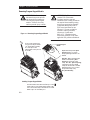
Important: Before you install and start up the
controller, inspect the mechanical integrity of the
system (e.g., look for loose parts, wires,
connections, etc.).
In addition to the precautions listed throughout
this manual, you must read and understand the
following statements which are general to the
system.
A
TTENTION:
Thi
s c
ontroller
contains ESD (Electrostati
c D
ischarge)
sensitiv
e p
art
s a
n
d a
ssemblies. Static
control precaution
s a
re required when
installing, testing
, s
ervicing or
repairing thi
s a
ssembly
. C
omponent
damage may result if ES
D c
ontrol
procedure
s a
r
e n
ot followed. If you
ar
e n
ot familiar wit
h s
tati
c c
ontrol
procedures, referenc
e A
-
B P
ublication
8000-4.5.2
, “
Guarding Against
Electrostati
c D
amage
” o
r any other
applicable ESD protection handbook.
A
TTENTION:
Only personnel
familiar with the controller and
associated machinery should plan or
implement the installation, start-up,
and subsequent maintenance of the
system. Failure to comply may result
in personal injury and/or equipment
damage.
A
TTENTION:
The surface
temperatures of the controller may
become hot, which may cause injury.
A
TTENTION:
An incorrectly
applied or installed controller can
result in component damage or
reduction in product life. Wiring or
application errors such as undersizing
the motor, supplying an incorrect or
an inadequate AC supply
, or
excessive ambient temperatures may
result in system malfunction.
A
TTENTION:
The controller
contains high voltage capacitors
which take time to discharge after
removal of mains supply. Before
working on controller
, ensure
isolation of mains supply from line
inputs [L1, L2, L3 (U, V, W)]. Wait
one minute for capacitors to
dischar
ge to safe voltage levels.
Failure to do so may result in
personal injury or death.

Chapter 1 -
1–2
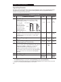
Figure
1.1 - Catalog Number Code Explanation
160
- A A04 N SF1 P1
Bulletin
Number
Current
Rating
Enclosure
Type
V
oltage Rating
A01
A02
A03
A04
A06
A08
A12
Letter Type
N
Open (IP20)
P
Chassis Mount
À
(external
heatsink)
F
NEMA 4
À
(IP66)
A
200Ć240V 1
∅
200Ć240V 3
∅
B
380Ć460V 3
∅
First
Position
Second
Position
Third
Position
Fourth
Position
Sixth
Position
Control
Fifth
Position
Programmer
(Optional)
SF1 = Analog
Signal
Follower
PS1 = Preset
Speed
Program
Keypad Module
An S" in the
Bulletin Number
denotes a single
phase input
voltage.
À ""!
!
Figure
1.2 - Nameplate Information
CAT160–AA04NSF1P1 SER B
I
N
P
U
T
V:
A:
Hz:
VA:
O
U
T
P
U
T
V:
A:
Hz:
3∅
Motor
Rating:
200-240
5.4
50/60
2200
200-230
4.5
0-240
0.75kW/1HP
ALLEN-BRADLEY
MADE
IN U.S.A.
Nameplate is located on the
side of the unit.
3∅
S/N 32098
IP20
OPERATING
AMBIENT TEMP: 0 – 50
°C
SHORT CIRCUIT CURRENT
: 100KA
POWER TERMINAL WIRE: Use 75°
C Cu Wire
4mm
2
– .75mm
2
(12–18 A
WG.)
T
orque 1.35 Nm (12 in.-lbs.)
W
ARNING: ! Allow 1 Minute after power is removed
before servicing. Accessible surfaces may be hot.
Compatible with T
ype B RCD protection devices only.
FRN:
5.xx
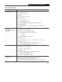
Conventions Used In This Manual
Parameter numbers and names are shown in bold typeface and follow the format PXX – [*] where P
denotes parameter, XX denotes the two digit parameter number, and * represents the parameter name.
For example, P01 – [Output Frequency].

2
!
!!
2–1
!!!
Take these actions to prolong controller life and
performance:
D store within an ambient temperature range of
–40_
to +85
_C
D store within a relative humidity range of 0%
to 95%, non-condensing
D protect the cooling fan by avoiding dust or
metallic particles
D avoid storing or operating the controller where
it could be exposed to a corrosive atmosphere
D protect from moisture and direct sunlight
D operate at an ambient temperature range of 0_
to +50
_C
To maintain proper working conditions, install the
controller on a flat, vertical and level surface. Use
mounting screws up to 4.5mm (0.177 inches) in
diameter or mount on 35mm DIN Rail.
!#
This product complies with Electromagnetic
Compatibility (EMC) Directive 89/336/EEC,
when the following requirements for a
conforming installation are applied:
D an input line filter must be installed to reduce
conducted emissions. Refer to the accessory
list in Appendix A. When using the filters
listed in Appendix A, the maximum motor
cable lengths are 75m (250 feet) for 230V
controllers and 40m (133 feet) for 460V
controllers.
D the controller system must be mounted in a
shielded enclosure to reduce radiated
emissions. A typical NEMA or IEC metal
enclosure is adequate.
D motor cables must be in grounded metal
conduit, or have shielding/armor with
equivalent attenuation to reduce radiated
emissions.
D control and signal wiring must be in grounded
metal conduit or have shielding with
equivalent attenuation.
$!!#
This product complies with Low Voltage
Directive 72/23/EEC when conforming with the
following installation requirements:
D review the General Precautions section on
page 1–1, inside front cover, and other
ATTENTION statements throughout this
manual prior to installation of the controller.
D the controller is intended to be installed with a
fixed connection to the earth. The use of
residual-current-operated protective devices
(RCDs) or ground fault indicators is not
recommended. If unavoidable, the Bulletin
160 is compatible with type B RCDs only
.
D the controller should be installed in an
appropriate or suitable enclosure.
Important: The conformity of this controller and
filter to any standard does not guarantee that the
entire installation will conform. Many factors can
influence the total installation and only direct
measurements can verify total conformity.
A copy of the Declaration of Conformity (DOC)
is available from your local Rockwell Automation
sales of
fice.
"!"!
! !
"" "&&
!!
"
#("'"&%)&
!*
#("'"
#%$(
'#!
"
D See Appendix A for details on controller
dimensions and weights.
D There must be a minimum of 12.5mm
(0.5 inches) clearance around all sides of the
controller. Use either DIN rail or mounting
holes. (Use the drilling template at the back of
the manual for mounting the controller.)
D Leave debris cover attached during controller
installation to protect from falling debris. To
ensure proper controller operation, remove
cover before applying power.

Chapter 2 - ',-%%-#('#+#'!
2–2
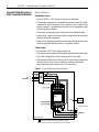
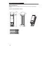
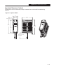
Controller Features
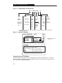
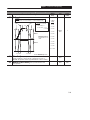
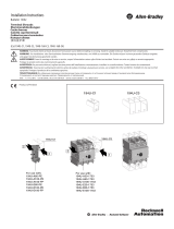
Figure 2.1 below details the features of both the
Analog Signal Follower and Preset Speed models.
Important: The features are the same for single
and three phase units.
Figure 2.1
- Controller Features
Ground Tab/
Protective Earth
Terminal Block One
(TB1) -
#
À
Terminal Block Three
(TB3) -
!
Terminal Block Two
(TB2) -
!
À
Ready/Fault
Indicating Panel
!"!
! Ã
Fan
LEDs -
!
! !!"
FAULT Á
876543219110 1
READY
Â
ST
-
L3L2L1
BR
+
R
T
1
T
2
T
3
+
VDCDC
-
UW
DIN Latch
BR
À
+-(#!.+
Á " + #'#-(+ #%%.&#'-, 0"' ('-+(%%+ .%-
('#-#('
1#,-, +-(")-+ (+-#%,('"(0-(%+
.%-
'
!'+%-+(.%,"((-#'!)+(.+,
 "!+'#'#-(+#%%.&#'-,0"'-".,#,
"+!'-"('-+(%%+#,+2-(+.'
à .%%-#' ('-+(%%+,+ .%%2 .'-#('%0"' #',-%% 0#-"
2.%- #'#-#'! )'% %% ('-+(% .'-#(', '
)+ (+& +(&-"('-+(%-+&#'%%($-(+2 .%-
)+&-+ ,--#'!, ''(- "'! 0#-" -" 2.%-
#'#-#'!
)'%
"!'(++,)+-%2-%(!
(+, -(+24#',-%%()-#('2#'!3-(-"'
(
-"-%(!'.&+
+-(")-++(!+&2)(.%
(+
-#%1)%'-#('( .'-#('%#-2
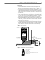
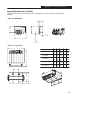
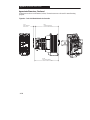
Figure 2.2
- Power W
iring For Analog
Signal Follower and Preset Speed Models
Terminal
Block One
(TB1) -
#
!
ST
-
L3L2L1
B
R
B
R
+
R
T
1
T
2
T
3
+
VDCDC
-
UW
Terminal Block
T
wo (TB2) -
!
!
"
Required Branch
Circuit Disconnect
Å
Dynamic Brake
Module Option Æ
!
Ç
Capacitor Module
Option È
Input Line Protective Device -
Å (+,#'!%)",#').-))%#-#(',(''--"#').-%#'-(
#').--+&#'%,'
Æ (''-#(' (+2'&#+$+,#,-(+, (+%%&(%,
&.,- '% (+ )+()+
()+-#('
))'#1 (+)+-'.&+,
Ç .%%-#'('-+(%%+,+ ' %#,-,&(-(+
(/+%()+(--#//#,'1-+'%
(/+%(+%2#,'(-+*.#+
(+,#'!%&(-(+))%#-#(',
È
(''-#(' (+'1-+'%)#-(+&(.%+(/#,1-'
+#-"+(.!")#%#-2'#&)+(/#'"+'-+$#'!
)+ (+&'))'#1 (+)+-'.&+
ATTENTION: The controller is
intended to be commanded by control
input signals that will start and stop the
motor. A device that routinely disconnects
then reapplies line power to the controller
for
the purpose of starting and stopping the
motor
should not be used.
If it is necessary
to use this method for starting and
stopping
or if frequent cycling of power is
unavoidable, make sure that it does not
occur more than once a minute.
ATTENTION: Do not connect power
factor correction capacitors to controller
output terminals T1, T2, and T3 (U, V,
and
W)
or component damage could occur
.

Chapter 2 - ,01 ** 1(-,(/(,&
2–3
Power Wiring For Preset Speed and
Analog Signal Follower Models
Table 2.A Power
T
erminal Block Specifications
Terminal
Block
Screw
Size
Max/Min Wire
Size mm
2
(A
WG)
Max/Min Torque
Nm. (lb.in.)
TB1
À
M4 4-0.75 (12-18)
1.81-1.35 (16-12)
TB2
À
M4 4-0.75 (12-18)
1.81-1.35 (16-12)
À '$2**$1(,(03(1'3(/$0(,01 **$#-,.-3$/
1$/+(, *!*-")0
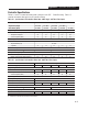
Recommended Line Side Protection
The Bulletin 160 Smart Speed Controller has
been UL tested and approved for use with up to a
30 Amp protective device (fuse, circuit breaker,
manual motor starter) installed on the line side of
the drive for the purposes of branch circuit
protection. The ratings in T
ables 2.B and 2.C are
the minimum recommended values for use with
each drive rating. The model numbers of the
devices listed in these tables are provided to serve
as a guide. Other devices which meet the
requirements of UL508C and UL489 with similar
trip characteristics may be used. For applications
with greater than five controllers per branch
circuit, consult factory for group fusing
recommendations.
Input Power Conditioning
The controller is suitable for direct connection to
AC power lines within the rated voltage of the
controller (see Appendix A). Listed below are
certain power line conditions which may cause
component damage or reduction in product life. If
any of the conditions exist as described in the
table below
, install “one” of the devices listed
under the heading “Corrective Action” on the line
side of the controller. Note: Only one device per
branch circuit is required. It should be mounted
closest to the branch and sized to handle the total
current of the branch circuit.
Power Line Condition Corrective Action
Low
Line Impedance (less than
1% line reactance)
Line Reactor (See A-4) or
Isolation Transformer
Line has power factor correction
capacitors
Line Reactor (See A-4) or
Isolation Transformer
Line has frequent power
interruptions
Line Reactor (See A-4) or
Isolation Transformer
Line has high frequency
(>10 Hz) noise spikes in excess of
900V (Induction heaters, RF
equipment, choppers)
MOV option (See A-4) or
Line Reactor (See A-4) or
Isolation Transformer
Line has intermittent noise spikes
in excess of 2000V (lightening)
MOV option (See A-4) or
Line Reactor (See A-4) or
Isolation Transformer
Table 2.B Recommended
Line Side Protective Devices for 200-240V rated units
3 ∅
Rating
kW (HP)
1
∅
Rating
kW (HP)
Fuse
Rti
Fuse Types
Ç
Other Protective Devices
∅
g
kW (HP)
∅
g
kW (HP)
Rating
Class CC
Class J
Rating Type
.37 (1/2)
N/A 6 16
.
37
(1/2)
.55 (3/4)
N/A
.37 (1/2)
6
6 KLDR/CCMR
Á
JDT
Á
16
16 140-MN-****
Ä
.
55
(3/4)
.75 (1)
.
37
(1/2)
.55 (3/4)
6
10
KLDR/CCMR
ATMR
Â
JDT
AJT
Â
16
16
140 MN
1492-CB3-H***
Å
.
75
(1)
1.5 (2)
.
55
(3/4)
.75 (1)
10
15 (16)
ATMR
FNQR
Ã
AJT
LPJ
Ã
16
16
1492 CB3 H
HFD ***L
Æ
1
.
5
(2)
2.2 (3)
.
75
(1)
1.5 (2)
15
(16)
25
FNQR
LPJ
16
20
HFD
L
Table 2.C Recommended
Line Side Protective Devices for 380-460V rated units
3 ∅
Rating
kW (HP)
1
∅
Rating
kW (HP)
Fuse
Rti
Fuse Types
Ç
Other Protective Devices
∅
g
kW (HP)
∅
g
kW (HP)
Rating
Class CC
Class J
Rating Type
.37
(
1
/
2
)
N
/
A 3
(
4
)
À
16
.
37
(1/2)
.55
(
3/4
)
N/A
N/A
3
(4)
À
3
(
4
)
À
KLDR/CCMR
Á
Â
JDT
Á
Â
16
16
140-MN-****
Ä
Å
.
55
(3/4)
.75 (1)
N/A
N/A
3
(4)
6
À
KLDR/CCMR
ATDR/ATQR
Â
Ã
JDT
AJT
Â
Ã
16
16
140 MN
1492-CB3-H***
Å
Æ
.
75
(1)
1.5 (2)
N/A
N/A
6
10
ATDR/ATQR
FNQR
Ã
AJT
LPJ
Ã
16
16
1492 CB3 H
HFD ***L
Æ
1
.
5
(2)
2.2 (3)
N/A
N/A
10
15 (16)
FNQR
LPJ
16
20
HFD
L
À
201!$#2 *$*$+$,1
1(+$#$* 4
Á (11*$%20$
Â
-2*#' 3+21
à 200+ ,
Ä
**$,/ #*$42**$1(,
+ ,2 *+-1-/
01 /1$/
Å **$,/ #*$4
2**$1(,"(/"2(1
!/$ )$/
Æ
$01(,&'-20$14.$
"(/"2(1!/$ )$/
Ç -,1/-**$/(0 *0-
"-+. 1(!*$3(1'
,#
%20$14.$0
20$/ 1(,&0(,#$,-1$
2/-.$ ,0(5$

%&&! $
2–4
A variety of cable types are acceptable for
variable speed controller installations. For many
installations,
unshielded
cable is adequate,
provided it can be separated from sensitive
circuits. As an approximate guide, allow a
spacing of 1 meter (3.3 feet) for every 10 meters
(33 feet) of unshielded length. If you cannot
separate motor cables from sensitive circuits, or if
you must run motor cables from multiple
controllers (more than three) in a common
conduit or cable trays, shielded motor cable is
recommended to reduce system noise.
Motor cables should be four-conductor with the
ground lead and shield (if using shielded cable)
connected to the controller ground terminal and
the motor frame ground terminal.
Installations with long motor cables may require
the addition of output reactors to reduce voltage
reflections at the motor
, and reduce cable
charging current. Capacitive charging of long
motor cables may draw current in excess of the
controller rating. The controller should be
installed as close to the motor as possible.
Important:
Both Reflected W
ave and Capacitive
Current Considerations need to be taken into
account when determining motor cable lengths.
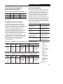
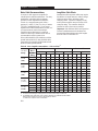
Refer to Table 2.D and Table 2.E .
#
"
"
380–460 V
Ratin
g
s
!
Ratings
!
1000 Vp-p
40 12 40 12 40 12 40 12 210 64 210 64
2.2 kW
(3 HP)
1200 Vp-p
60 18 60 18 180 55 180 55 260 79 260 79
(3
HP)
1600 Vp-p
500
152
500
152
500
152
500
152
500
152
500
152
1000 Vp-p
40 12 40 12 45 14 50 15 250 76 250 76
1.5kW
(2 HP)
1200 Vp-p
60 18 60 18 300 91 200 61 340 104 340 104
(2
HP)
1600 Vp-p
500
152
500
152
500
152
500
152
500
152
500
152
1000 Vp-p
55 17 40 12 55 17 40 12 325 99 325 99
0.75 kW
(1 HP)
1200 Vp-p
125 43 60 18 180 55 120 37 500 152 325 99
(1
HP)
1600 Vp-p
500
152
500
152
500
152
500
152
500
152
500
152
1000 Vp-p
45 14 40 12 45 14 40 12 300 91 300 91
0.55 kW
(0.75 HP)
1200 Vp-p
125 38 60 18 75 23 75 23 500 152 500 152
(0
.
75
HP)
1600 Vp-p
500
152
500
152
500
152
500
152
500
152
500
152
1000 Vp-p
45 14 40 12 45 14 40 12 300 91 300 91
0.37 kW
(0.5 HP)
1200 Vp-p
125 38 50 15 75 23 75 23 500 152 500 152
(0
.
5
HP)
1600 Vp-p
500
152
500
152
500
152
500
152
500
152
500
152
$&)(&""%&!$#' %&!+!$$& %%
*'",&!,"(!&!&! &$!$%'&!& '! !&%!&)$
&((
%& % ! ! &%'"&!&
!$"&('$$ &! %$&! %

2–5
$ "!
"
380–460 V
Ratin
g
s
Ratings
#
2 360 110 750 229 650 198 800 244 410 125 525 160
2.2 kW
(3 HP)
4 335 102 600 183 625 191 750 229 370 113 475 145
(3
HP)
8 300 91 410 125 600 183 700 213 310 94 420 128
2 300 91 540 165 550 168 700 213 310 94 425 130
1.5 kW
(2 HP)
4 300 91 425 130 525 160 650 198 300 91 400 122
(2
HP)
8 300 91 300 91 500 152 600 183 300 91 350 107
2 300 91 375 114 320 98 650 198 300 91 300 91
0.75 kW
(1 HP)
4 300 91 300 91 300 91 600 183 300 91 300 91
(1
HP)
8 300 91 300 91 300 91 550 168 300 91 300 91
2 300 91 375 114 320 98 600 183 300 91 300 91
0.55 kW
(0.75 HP)
4 300 91 310 94 300 91 565 172 300 91 300 91
(0
.
75
HP)
8 300 91 300 91 300 91 525 160 300 91 300 91
2 300 91 375 114 320 98 550 168 300 91 300 91
0.37 kW
(0.5 HP)
4 300 91 325 99 300 91 530 162 300 91 300 91
(0
.
5
HP)
8 300 91 300 91 300 91 500 152 300 91 300 91
"
200–240 V
Ratin
g
s
Ratings
0.37 to 2.2 kW
(0.5 to 3 HP)
2 thru 8 kHz
500 152 800 244 800 244 800 244 500 152 800 244

Chapter 2 -
2–6
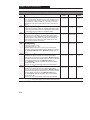
Control Wiring Requirements
run all signal wiring in either a shielded cable,
or a separate metal conduit.
only connect shield wire at control terminal
block common terminals TB3-3 and TB3-7.
do not exceed control wiring length of 15
meters (50 feet). Control signal cable length
is highly dependent on electrical environment
and installation practices. To improve noise
immunity the control terminal block common
must be connected to earth ground.
use Belden 8760 (or equivalent) — 18AWG
(0.750mm
2
), twisted pair, shielded or 3
conductor.
Table 2.F Control
T
erminal Block Specifications
Terminal
Block
Max/Min
Wire Size
mm
2
(A
WG)
Max/Min
Torque
Nm. (lb.in.)
TB3 2.5–0.5
(14–22)
0.8–0.4
(8–4)
ATTENTION: The controller is
supplied with an internal 12V supply.
Dry contacts or open collectors are
required for discrete control inputs.
If an external voltage is applied,
component damage could occur.
A
TTENTION:
The drive start/stop
control circuitry includes solid-state
components. If hazards due to
accidental contact with moving
machinery or unintentional flow of
liquid, gas or solids exist, an
additional hardwired stop circuit is
required to remove AC line power to
the drive. When AC input power is
removed, there will be a loss of
inherent regenerative braking effect
and the motor will coast to a stop. An
auxiliary braking method may be
required.
Control Wiring - Analog Signal Follower
Model
You can control the output frequency of the
controller via the Control Terminal Block (TB3)
using a remote potentiometer
, a –10 to +10 VDC
analog input, a 4–20mA analog input, or use
P58 – [Internal Frequency].
Important: Only
one frequency source may be connected at a time.
If the frequency reference potentiometer and the
4–20 mA reference are connected at the same
time, an undetermined frequency reference will
result.
Control Wiring - Preset Speed Model
You can control the output frequency of the
controller via the Control Terminal Block (TB3)
using dry contacts or open collector inputs to
SW1, SW2, and SW3 or use P58 – [Internal
Frequency]. A program keypad module is
required to change the factory default settings.
Refer to Chapter 5,
parameters 61–68
for the
eight preset frequency factory default settings and
switch configurations.
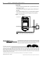
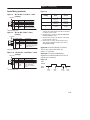
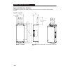
Wiring Diagrams
Important: Refer to the diagrams on the
following pages for control wiring information.

Chapter 2 - !""
2–7
Control Wiring
8
7
6
5
4
3
2
1
9
1
10
1
+
10V Pot
Pot Wiper or
+10/-10 VDC Input
Common
4-20mA Input
Reverse
Start
Common
Stop
Normally Closed
Relay Common
Normally Open
Signal Specification
Ω
"'!'" '%
''&
"!'%"%!#(' #!
Ω
"!'%"%!#(' #!
Ω
"!''"&(%!#('%$(%'""#%'"!'%"%
"!''"&(%!#('
"!''"&(%!#('
Terminal
TB3
(&'" %+#%"% %*"('#('&
&&')"'
'
!(')"'
'
FAULT
READY
Figure 2.3
- TB3 Control W
iring for Analog Signal Follower Model
FAULT
READY
8
7
6
5
4
3
2
1
9
1
10
1
SW1
SW2
Common
SW3
Reverse
Start
Common
Stop
Normally Closed
Relay Common
Normally Open
Signal Specification
"!''"&(%!#('
" !#'
"!''"&(%!#('
"!''"&(%!#('
"!''"&(%!#('%$(%'""#%'"!'%"%
"!''"&(%!#('
"!''"&(%!#('
TerminalTB3
(&'" %+#%"%
%*"('#('&
&&')"'
'
!(')"'
'
%
Figure 2.4
- TB3 Control W
iring for Preset Speed Model
"&" % "" !"
"
!"!'"
" $ "!"" "! $!#"'"" "
#!""" " #
! !%!(" % " ""% !" " % "!
" "!
" "!
%
!'!"!''
" !'%*"!''
" !'%*"!''
" "!
!'!"!''
" !'%*"!''
" !'%*"!''
" "!
La page charge ...
La page charge ...
La page charge ...
La page charge ...
La page charge ...
La page charge ...
La page charge ...
La page charge ...
La page charge ...
La page charge ...
La page charge ...
La page charge ...
La page charge ...
La page charge ...
La page charge ...
La page charge ...
La page charge ...
La page charge ...
La page charge ...
La page charge ...
La page charge ...
La page charge ...
La page charge ...
La page charge ...
La page charge ...
La page charge ...
La page charge ...
La page charge ...
La page charge ...
La page charge ...
La page charge ...
La page charge ...
La page charge ...
La page charge ...
La page charge ...
La page charge ...
La page charge ...
La page charge ...
-
 1
1
-
 2
2
-
 3
3
-
 4
4
-
 5
5
-
 6
6
-
 7
7
-
 8
8
-
 9
9
-
 10
10
-
 11
11
-
 12
12
-
 13
13
-
 14
14
-
 15
15
-
 16
16
-
 17
17
-
 18
18
-
 19
19
-
 20
20
-
 21
21
-
 22
22
-
 23
23
-
 24
24
-
 25
25
-
 26
26
-
 27
27
-
 28
28
-
 29
29
-
 30
30
-
 31
31
-
 32
32
-
 33
33
-
 34
34
-
 35
35
-
 36
36
-
 37
37
-
 38
38
-
 39
39
-
 40
40
-
 41
41
-
 42
42
-
 43
43
-
 44
44
-
 45
45
-
 46
46
-
 47
47
-
 48
48
-
 49
49
-
 50
50
-
 51
51
-
 52
52
-
 53
53
-
 54
54
-
 55
55
-
 56
56
-
 57
57
-
 58
58


Allen-Bradley 160 SSC Guide d'installation
- Taper
- Guide d'installation
dans d''autres langues
Documents connexes
-
 Allen-Bradley Micro800 Installation Instructions Manual
-
 Allen-Bradley CompactLogix 1769-L30 Installation Instructions Manual
-
 Allen-Bradley ControlLogix 1756-IF4FXOF2F Installation Instructions Manual
-
 Allen-Bradley MicroLogix 1200 Installation Instructions Manual
-
 Allen-Bradley ControlLogix 1756-IF6CIS Installation Instructions Manual
-
 Allen-Bradley FLEX I/O 1794-IG16 Installation Instructions Manual
-
 Allen-Bradley 1785 PLC-5 Manuel utilisateur
-
 Allen-Bradley SLC 500 Series Installation Instructions Manual
-
 Allen-Bradley 802T Guide d'installation
-
 Allen-Bradley 1492-PDE1C142 Installation Instructions Manual


Autres documents
-
Rockwell Automation 1766-L32BXBA Installation Instructions Manual
-
Rockwell Automation 2080-LC10-12AWA Installation Instructions Manual
-
 TELEMECANIQUE ALTIVAR 31 Le manuel du propriétaire
-
Spectrum Controls 2080sc-OW2IHC Le manuel du propriétaire
-
 Rockwell Automation Bulletin 193 E1 PLUS Application And Installation
-
Cooper Lighting 6- ControlKeeper 4A - CK4A Guide d'installation
-
Seura SPK-86 Manuel utilisateur
-
Toro 12-32 Rear Engine Rider Manuel utilisateur
-
-
 Rockwell Automation Allen-Bradley 194U Series Guide d'installation


