Hobart CL44eN Instructions Manual
- Catégorie
- Lave-vaisselle
- Taper
- Instructions Manual

701 S. RIDGE AVENUE
TROY, OHIO 45374-0001
937 332-3000
www.hobartcorp.com
F47607 (February 2017)
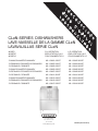
CLeN-SERIES DISHWASHERS
LAVE-VAISSELLE DE LA GAMME CLeN
LAVAVAJILLAS SERIE CLeN
MODEL R-L OPERATION L-R OPERATION
MODÈLE EXPLOITATION D A G EXPLOITATION G A D
MODELO FUNCIONAMIENTO D-I FUNCIONAMIENTO I-D
CL44eN/CL44eNER/CL44eNADV ML-138401-0000Z ML-138402-0000Z
CLPS66eN/CLPS66eNER/CLPS66eNADV ML-138403-0000Z ML-138404-0000Z
CLCS66eN/CLCS66eNER ML-138409-0000Z ML-138410-0000Z
CL54eN/CL54eNER/CL54eNADV ML-138405-0000Z ML-138406-0000Z
CLPS76eN/CLPS76eNER/CLPS76eNADV ML-138407-0000Z ML-138408-0000Z
CLCS76eN/CLCS76eNER ML-138411-0000Z ML-138412-0000Z
CL64eN/CL64eNER/CL64eNADV ML-138413-0000Z ML-138414-0000Z
CLPS86eN/CLPS86eNER/CLPS86eNADV ML-138415-0000Z ML-138416-0000Z
CLCS86eN/CLCS86eNER ML-138417-0000Z ML-138418-0000Z
E

– 2 –
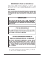
IMPORTANT FOR YOUR SAFETY
THIS MANUAL HAS BEEN PREPARED FOR PERSONNEL QUALIFIED
TO INSTALL GAS EQUIPMENT, WHO SHOULD PERFORM THE INITIAL
FIELD START-UP AND ADJUSTMENTS OF THE EQUIPMENT COVERED
BY THIS MANUAL.
POST IN A PROMINENT LOCATION THE INSTRUCTIONS TO BE
FOLLOWED IN THE EVENT THE SMELL OF GAS IS DETECTED. THIS
INFORMATION CAN BE OBTAINED FROM THE LOCAL GAS SUPPLIER.
IMPORTANT
IN THE EVENT A GAS ODOR IS DETECTED, SHUT DOWN UNITS
AT MAIN SHUTOFF VALVE AND CONTACT THE LOCAL GAS
COMPANY OR GAS SUPPLIER FOR SERVICE.
FOR YOUR SAFETY
DO NOT STORE OR USE GASOLINE OR OTHER FLAMMABLE
VAPORS OR LIQUIDS IN THE VICINITY OF THIS OR ANY OTHER
APPLIANCE.
FOR YOUR SAFETY
READ BEFORE OPERATING
DO NOT USE THIS APPLIANCE IF ANY PART HAS BEEN
UNDER WATER. IMMEDIATELY CALL A QUALIFIED SERVICE
TECHNICIAN TO INSPECT THE APPLIANCE AND TO REPLACE
ANY PART OF THE CONTROL SYSTEM AND ANY GAS
CONTROL WHICH HAS BEEN UNDER WATER.
IN THE EVENT OF A POWER FAILURE, DO NOT ATTEMPT TO
OPERATE THIS DEVICE.
© HOBART 2017

– 3 –
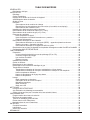
TABLE OF CONTENTS
GENERAL ............................................................................4
Chemical Sanitizing . ................................................................5
INSTALLATION ........................................................................5
Unpacking .........................................................................5
Installation Codes ...................................................................5
Adjust Machine Height and Level Machine . ..............................................5
Dish Table Assembly . ...............................................................5
Water Requirements .................................................................6
Plumbing Connections . ..............................................................7
Drain Connection ................................................................7
Drain Water Tempering Kit (If Equipped) ..............................................7
Water Connections . .............................................................7
Chemical Feeder Installations . ........................................................8
Steam Connection (When Equipped for Steam Heat) . ......................................9
Gas Connection (When Equipped for Gas Heat) ...........................................9
Venting Requirements ..............................................................10
Type II Canopy Hood . ..........................................................10
Pant-Leg Vent Connections .......................................................12
Exhaust Flow Requirements ......................................................14
Electrical Connections – Dishwasher ...................................................14
Single-Point Electrical Connection (S.P.E.C.) Three-Phase Only ..........................15
Motor Rotation - Three-Phase Only . ...............................................15
Optional Equipment Control Connections ............................................16
CLeNER and CLeNADV Energy Recovery Set-Up . .......................................16
'HOLPH1RWL¿FDWLRQ6HWXS ............................................................18
OPERATION .........................................................................19
Preparation .......................................................................19
If Equipped with Scrapper (PS/CS) .................................................19
Wash/Rinse Tanks ..............................................................19
CLeNADV Models ..............................................................20
Curtains & Doors ...............................................................20
Curtain Installation . ................................................................21
Keypad and Display . ...............................................................23
Filling the Dishwasher . .............................................................24
Starting the Gas Heat Dishwasher .....................................................24
Minimum Temperatures . ............................................................24
Minimum Temperatures Using High-Temperature Sanitizing . ............................24
Minimum Temperatures Using Low-Temperature, Chemical Sanitizing . ....................25
Alternative Temperature Display Names .............................................25
Low FR Temp Alert . ............................................................25
Tank Temperature Alert ..........................................................25
Dishwashing ......................................................................26
Pot and Pan Mode ..............................................................27
Optional Table Limit Switch .......................................................27
Auto-Timer ....................................................................27
Energy Saver Mode .............................................................27
Dirty Water Mode. . . . . . . . . . . . . . . . . . . . . . . . . . . . . . . . . . . . . . . . . . . . . . . . . . . . . . . . . . . . . . . 27
CLEANING ..........................................................................28
Deliming Procedure . ...............................................................30
Clearing the DHOLPH5HFRPPHQGHG1RWL¿FDWLRQ ..........................................31
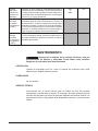
DOs and DON'Ts for Your New Hobart Warewasher . ......................................31
PROGRAMMING . ....................................................................32
Programming Security Levels .........................................................32
Programming Instructions ............................................................33
Menu Display Prompts
..............................................................33
Entering the Parameters Menu ........................................................34
Navigating the Parameters Menu ......................................................34
MAINTENANCE ......................................................................36
Vent ............................................................................36
Lubrication . ......................................................................36
Service ..........................................................................36
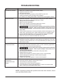
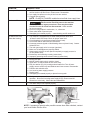
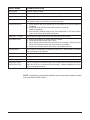
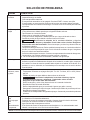
TROUBLESHOOTING . ................................................................37

– 4 –
Installation, Operation and Care Of
CLeN-SERIES DISHWASHERS
SAVE THESE INSTRUCTIONS
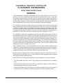
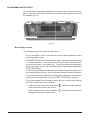
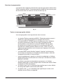
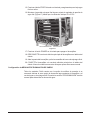
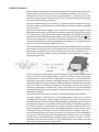
GENERAL
CLeN machines are rack-type warewashers that move the racks from one end of the
machine to the other, exposing the ware to progressive wash and rinse zones. Pumps and
¿QDOULQVHDUHDFWLYDWHGE\WKHLQVHUWHGUDFNWRHQHUJL]HWKHVSHFL¿FZDVKRUULQVHDFWLRQ
needed. The CLeN-series machines are offered in optional lengths, sections, features, and
provide different speeds to meet productivity and performance requirements. All CLeN-
Series Dishwashers have electronic controls with digital temperature displays.
The CLeNER models have a drain water energy recovery system which includes drain
water tempering and all of the standard features of the CLeN. They use a heat exchanger
WRFDSWXUHWKHHQHUJ\IURPWKHGUDLQZDWHUDQGSUHKHDWLQFRPLQJFROGZDWHUIRUWKH¿QDO
rinse. The CLeNER units are only available in hot water sanitizing mode, three phase, and
FRPHVWDQGDUGZLWKDEXLOWLQN:ERRVWHUKHDWHUZKLFKLVGHVLJQHGWRPDLQWDLQ¿QDOULQVH
temperature of 180°F with a minimum incoming cold water temperature of 55 °F.
The CLeNADV models have an Automatic Soil Removal (ASR) system and include all of
the standard features of the CLeNER. The ASR system automatically redirects food soil left
over after pre-scrapping to an external scrap basket located at the load end of the machine.
This helps to keep the wash water cleaner, reducing the frequency of water changes. This
saves the customer money on chemicals and water/energy. The CLeNADV-Series machines
are only available in hot water sanitizing mode, electric heat, three phase voltage supply,
and come standard with a 30KW built-in booster heater. The CLeNADV models are not
available with a corner scrapper unit (CLCS).
Tanks, chambers, frames, legs and adjustable feet are made of welded stainless steel
construction. Hinged inspection doors provide access to the interior wash and rinse zones.
CLPS models provide a 22-inch power scrapper section and hinged access door. The power
scrapper removes the heavy soil before the rack enters the wash zone.
Machines can be ordered as left-to-right or right-to-left operation. Either electric, gas, or
VWHDPWDQNKHDWLVVSHFL¿HGDWWLPHRIRUGHU0DFKLQHVFRPHVWDQGDUGUHDG\WRRSHUDWH
with high-temperature sanitizing mode.
Hobart offers three right-angle possibilities to put your machine in a corner installation:
7KH6LGH/RDGHUPRYHVWKHUDFNDWDULJKWDQJOHLQWRWKHPDFKLQHIURPWKHVFUDSSLQJ
area.
7KH'LUHFW'ULYH8QORDGHUPRYHVWKHUDFNDWDULJKWDQJOHFRPLQJRXWRIWKHPDFKLQHWR
tabling where the clean ware can be unracked.
7KH&RUQHU6FUDSSHU&/&6PRGHOVSXWVD3RZHU6FUDSSHULQWKHFRUQHUORFDWLRQDW
the load end of your machine, combining right angle entry with a scrapper section.

– 5 –
CHEMICAL SANITIZING
CLeN machines can be converted to operate with low-temperature sanitizing mode
(with the use of chemical sanitizers). Refer to Sanitation Mode programming
instructions on page 35. NOTE: Chemical sanitization is not available on the CLeNER
or CLeNADV models.
Hot water sanitizing mode is designated by "High Temp." on the display when the
machine is turned on. Low-temperature or chemical sanitizing mode is designated
by "Low Temp." on the display when the machine is turned on.
CLe1PRGHOVWKDWRSHUDWHZLWKFKHPLFDOVDQLWL]DWLRQXVHLQFRPLQJZDWHUDQG¿QDO
rinse water at 120°F minimum. Tank heaters raise that temperature to 130°F for
wash (and power rinse, if equipped).
INSTALLATION
UNPACKING
Immediately after unpacking the dishwasher, check for possible shipping damage.
If the machine is found to be damaged, save the packaging material and contact
the carrier within 5 days of delivery.
3ULRUWRLQVWDOODWLRQYHULI\WKDWWKHHOHFWULFDOVHUYLFHDJUHHVZLWKWKHVSHFL¿FDWLRQV
on the machine data plate, which is located on the left-hand side of the control box.
$IWHUXQSDFNLQJWKHGLVKZDVKHUUHPRYHWKHLWHPVVKLSSHGORRVHRYHUÀRZWXEHRU
standpipe, splash shields, curtains, extra wash arm caps, and literature envelope with
instructions and chamber hole plug kit) from inside the dishwasher. For CLeNADV
models only, remove the external ASR basket from inside the dishwasher and install
in the ASR housing located at the load end of the machine.
INSTALLATION CODES
Installation must be in accordance with state and local codes, or in the absence
of local codes, with the National Fuel Gas Code, ANSI Z223.1 (latest edition), if
applicable, and the National Electrical Code ANSI / NFPA 70 (latest edition). In
Canada, the installation standards are: CAN/CSA B149.1 and CSA C22.1 (latest
editions).
ADJUST MACHINE HEIGHT AND LEVEL MACHINE
Set the dishwasher in its proper location. Adjust the height and level the machine
by turning the adjustable feet in or out as necessary.
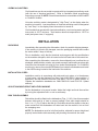
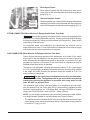
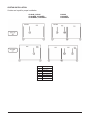
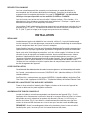
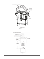
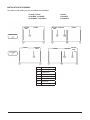
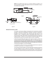
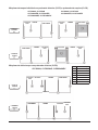
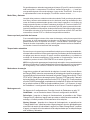
DISH TABLE ASSEMBLY
'LVKWDEOHVVKRXOGEH¿WWHGLQWRWKHGLVKZDVKHU)LJV8VHVLOLFRQHVHDODQW
between table and lip of tank to prevent leakage. Rack track height should be
from
1
/4 to
5
/16" (Fig. 2) above the tank lip. Dish tables should be sloped so that any
water carried from the dishwasher will drain back into the machine, but not from
the scrapping area.
NOTE: 7KHGLVKZDVKHUPXVWEHLQLWV¿QDOSRVLWLRQDGMXVWHGIRUSURSHUKHLJKWDQG
properly leveled before table assembly and plumbing connections are made.

– 6 –
Fig. 1
Fig. 2
Fig. 3
WATER REQUIREMENTS
Proper water quality can improve ware washing performance by reducing spotting,
enhancing effectiveness of labor and extending equipment life. Water conditions
vary from one location to another. The recommended proper water treatment for
HIIHFWLYHDQGHI¿FLHQWXVHRIWKLVHTXLSPHQWZLOODOVRYDU\GHSHQGLQJRQWKHORFDO
water conditions. Ask your municipal water supplier for details about local water
VSHFL¿FVSULRUWRLQVWDOODWLRQ
Recommended water hardness is 3 grains of hardness per gallon or less. Chlorides
must not exceed 30 parts per million. Water hardness above 3 grains per gallon
should be treated by a water conditioner (water softener or in-line treatment). Water
treatment has been shown to reduce costs associated with machine cleaning,
reduce deliming of the dishwasher and reduce detergent usage in the dishwasher.
6HGLPHQWVLOLFDFKORULGHVRURWKHUGLVVROYHGVROLGVPD\UHTXLUHSDUWLFXODWH¿OWUDWLRQ
or other water treatment.
If an inspection of the dishwasher or booster heater reveals lime buildup after
the equipment has been in service, in-line water treatment is recommended.
&RQWDFW\RXUORFDO+REDUW6HUYLFHRI¿FHIRUVSHFL¿FUHFRPPHQGDWLRQV

– 7 –
PLUMBING CONNECTIONS
Plumbing connections must comply with applicable sanitary,
safety and plumbing codes.
The plumber who connects this machine is responsible for making certain that both
water and steam lines are THOROUGHLY FLUSHED OUT BEFORE connecting to
any manual valve or solenoid valve.
7KLVµµÀXVKRXW¶¶LVQHFHVVDU\WRUHPRYHDOOIRUHLJQPDWWHUVXFKDVFKLSVUHVXOWLQJ
from cutting or threading of pipes), pipe joint compound from the lines or, if soldered
¿WWLQJVDUHXVHGELWVRIVROGHURUFXWWLQJVIURPWKHWXELQJ'HEULVLIQRWUHPRYHG
may lodge in the valves and render them inoperative. Manual valves or solenoid
valves found defective by foreign matter and any expenses resulting from this debris
are NOT the responsibility of the manufacturer.
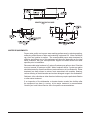
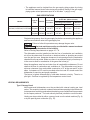
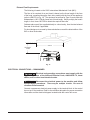
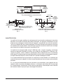
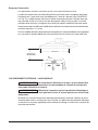
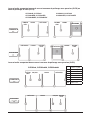
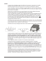
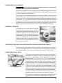
Drain Connection
The common drain for the tank(s) requires only
RQHFRQQHFWLRQWRWKHÀRRUGUDLQ7KHGUDLQ
can be connected at either end. A pipe plug
is provided for the opposite end. Connect the
drain (Fig. 4) through a trap to the sewer using
2" NPT pipe. If a grease trap is required by
FRGHLWVKRXOGKDYHDPLQLPXPÀRZFDSDFLW\
of 31 gallons per minute.
Drain Water Tempering Kit (If Equipped)
A drain water tempering kit is included with all CLeNER and CLeNADV models and
is available as an accessory for all base CLeN models. Refer to F-45654 CLeN Drain
Tempering Valve Installation Instructions supplied with the kit for proper installation.
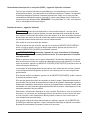
Water Connections
CLeN models require a single incoming hot water supply. CLeNER
and CLeNADV models require a hot and two cold water supplies.
Use
1
/2" minimum I.D. pipe size for the incoming water supply
OLQHVWRWKHPDFKLQH)LJ$ÀRZLQJSUHVVXUHRIWR
psig must be maintained at the machine. For long runs, use
larger pipe and insulation to ensure adequate pressure and
temperature. On CLeN models without built-in booster heater,
LI ÀRZ SUHVVXUH H[FHHGV SVLJ D SUHVVXUHUHGXFLQJ YDOYH
(by others) must be installed in the water supply line. On CLeN
models with built-in booster heater and all CLeNER and CLeNADV
models, pressure reducing valves are factory installed in the
water supply lines.
DRAIN CONNECTION
AT EITHER END
Fig. 4
Fig. 5
CLEANOUT
INCOMING WATER
STRAINER

– 8 –
For temperature requirements, refer to the Required Incoming Water
Temperature table below.
The water pressure regulator must have a relief bypass. Failure
to use the proper type of pressure regulator may result in damage to the
machine.
$SUHVVXUHJDXJHLVSURYLGHGIRUYHUL¿FDWLRQRISURSHUZDWHUSUHVVXUH
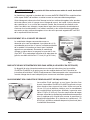
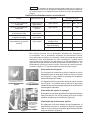
CHEMICAL FEEDER INSTALLATIONS
This machine must be operated with an automatic detergent feeder and, if
applicable, an automatic chemical sanitizer feeder, including a visual means
to verify that detergents and sanitizers are delivered or a visual or audible
alarm to signal if detergents and sanitizers are not available for delivery
to the respective washing and sanitizing systems. Chemical feeders are
supplied by others. For electrical connection, refer to Optional Equipment
Control Connections, page 16.
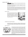
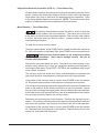
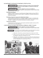
Detergent Feeder
Your chemical supplier will install a detergent feeder port
similar to the one shown in Fig. 6, that provides for discharge
of detergent into the wash tank.
An electric monitoring device, similar to the one shown in
Fig. 7, will be installed on the side of the wash tank to signal
the feeder to maintain the proper concentration of detergent.
Fig. 6 Fig. 7
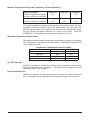
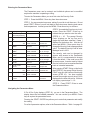
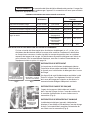
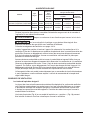
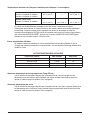
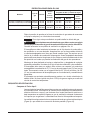
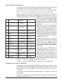
REQUIRED INCOMING WATER TEMPERATURE
Model Sanitizing Mode Connection Water Supply
Minimum Maximum
CLeN without Built-in
Booster
Hot Water Sanitizing Hot Water
180
°F (82°C) 194°F (82°C)
CLeN without Built-in
Booster
Chemical Sanitizing Hot Water
120°F (49°C)
N/A
CLeN with 15kW
Built-in Booster
Hot Water Sanitizing Hot Water
140°F (60°C)
N/A
CLeN with 30kW
Built-in Booster
Hot Water Sanitizing Hot Water
110°F (43°C)
N/A
CLeNER and
CLeNADV with 30kW
Built-in Booster
Hot Water Sanitizing Cold Water
(Final Rinse)
55°F (13°C)
N/A
Cold Water
(Drain Water
Tempering)
55
°F (13°C) 80°F (27°C)
Hot Water
110°F (43°C)
N/A

– 9 –
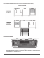
RINSE AID
AND / OR
CHEMICAL
SANITIZER
FEED PORTS
Fig. 8
Rinse Agent Feeder
5LQVHDJHQWLVW\SLFDOO\IHGLQWRWKH¿QDOULQVHZDWHUDWRQH
of the ports on the incoming water line below the pressure
gauge (Fig. 8).
Chemical Sanitizer Feeder
Chemical sanitizer (on
CLeN machines using low-temperature
VDQLWL]LQJLVIHGLQWRWKH¿QDOULQVHZDWHUOLQHDWWKHRWKHUSRUW
on the incoming water line below the pressure gauge (Fig. 8).
STEAM CONNECTION (When Machine is Equipped with Steam Tank Heat)
Steam supply pressure must agree with the steam trap (supplied) which
is rated for 10 to 50 psig differential pressure. ,IÀRZLQJSUHVVXUHH[FHHGVSVLJ
a pressure regulator (by others) must be installed in the supply line. 6WHDPÀRZLV
controlled by solenoid valves.
For single-tank steam coil installations, two connections are required, one for
supply and one for return. For two-tank steam coil installations, one common supply
connection and two return connections are required.
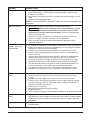
GAS CONNECTION (When Machine is Equipped with Gas Tank Heat)
Check the gas data plate attached to the dishwasher on the side of the control
box or refer to the tag attached to the gas burner tubing for the type of gas to be
XVHG$OOPDFKLQHVDUHVKLSSHGFRQ¿JXUHGIRUQDWXUDOJDV,IFRQYHUVLRQWR/3JDV
(propane) is required, a conversion kit with instructions is supplied and must be
installed before the machine is operated.
7KHEXUQHULVQRWDGMXVWDEOH,IÀRZLQJJDVSUHVVXUHLVDERYH:&QDWXUDOJDV
or 11" W.C. (propane gas), an additional regulator valve (by others) must be installed
in the supply line. Static incoming line pressure should not exceed 14.0" W.C. for
either propane or natural gas.
The gas supply line to the dishwasher must be provided with a
shut-off valve per code. The appliance and its gas connections must be leak
tested before placing the appliance in operation. Use soapy water for leak
WHVWV'2127XVHDQRSHQÀDPH
The installation must conform with local codes, or in the absence of local codes,
with the National Fuel Gas Code, ANSI Z223.1 (latest edition), available from the
American Gas Association, Inc., 1515 Wilson Blvd., Arlington, VA 22209. In Canada,
comply with CAN/CSA B149.1 and CSA C22.1 (latest editions).
NOTE: For gas line pipe connections, use Loctite 565, Hobart part number 546292,
RUDÀH[LEOHVHDODQWVXLWDEOHIRUXVHZLWK1DWXUDODQG3URSDQH*DVHV
7KHDSSOLDQFHDQGLWVLQGLYLGXDOVKXWRIIYDOYHPXVWEHGLVFRQQHFWHGIURPWKHJDV
supply piping system during any pressure testing of that system at test pressures
in excess of
1
/2 psig (3.45 kPa).

– 10 –
7KHDSSOLDQFHPXVWEHLVRODWHGIURPWKHJDVVXSSO\SLSLQJV\VWHPE\FORVLQJ
its individual manual shutoff valve during any pressure testing of the gas supply
piping system at test pressures equal to or less than
1
/2 psig (3.45 kPa).
Dissipate test pressure from the gas supply line before reconnecting the appliance
and its manual shutoff valve to the gas supply line.
Failure to follow this procedure may damage the gas valve.
Gas heat machines must be provided with a means to exhaust
WKHÀXHJDVHVWRWKHH[WHULRURIWKHEXLOGLQJ
Refer to Venting Requirements on pages 10 – 14.
7KHGLVKZDVKHUPXVWEHLQVWDOOHGVRWKDWWKHÀRZRIFRPEXVWLRQDQGYHQWLODWLRQ
air will not be obstructed. Ensure that no electrical cables or plumbing are routed
RYHUWKHJDVÀXHDUHD$GHTXDWHFOHDUDQFHVIRUDLURSHQLQJVLQWRWKHFRPEXVWLRQ
chamber must be provided. Make sure there is an adequate supply of make-up air
in the room to allow for combustion of the gas at the burner(s).
Keep the appliance area free and clear from all combustible substances. Do not
REVWUXFWWKHÀRZRIFRPEXVWLRQDQGYHQWLODWLRQDLU7KHGLVKZDVKHUPXVWKDYHD
minimum clearance from combustible construction of 3" at the rear and 0" at the
sides. A clearance of 23" must be provided at the front and 20" at each end of the
dishwasher for servicing and proper operation.
The burner is ignited automatically by solid-state electronic circuitry. There is no
SLORWOLJKW*DVÀRZLVUHJXODWHGE\WKHWHPSHUDWXUHFRQWUROFLUFXLW
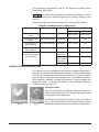
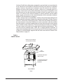
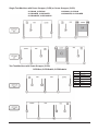
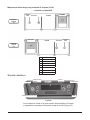
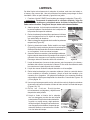
VENTING REQUIREMENTS
Type II Canopy Hood
Most commercial dishwashers must be provided with external venting per local
codes. The exception is electric or steam heat machines operating in the chemical or
low temperature sanitizing mode where the existing room ventilation will compensate
IRUWKHYDSRUVSURGXFHG7KHORFDODXWKRULW\KDV¿QDOMXULVGLFWLRQRYHUWKLVPDWWHU
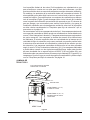
Venting can be provided by either a canopy hood over the whole machine (Fig. 9)
or by the pant-leg duct connection (Fig. 10).
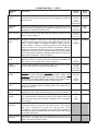
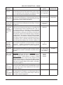
GAS SPECIFICATIONS
Models
Type of
Gas
BTU/Hr
Connection
Line Size
Flowing Gas Pressure - Not Static
Inches W.C. (Water Column)
Incoming Line Pressure
Manifold
Pressure
Minimum Maximum
CL44eN, CLPS66eN, CLCS66eN
CL54eN, CLPS76eN, CLCS76eN
Natural
Propane
78,000
78,000
1/2" NPT
1/2" NPT
3.5" W.C.
9.0" W.C.
7.0" W.C.
11.0" W.C.
3.2" W.C.
8.2" W.C.
CL64eN, CLPS86eN, CLCS86eN Natural
Propane
156,000
156,000
3/4" NPT
3/4" NPT
3.5" W.C.
9.0" W.C.
7.0" W.C.
11.0" W.C.
3.2" W.C.
8.2" W.C.

– 11 –
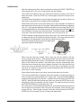
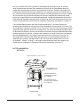
A Hobart CLeN-Series dishwasher equipped for gas tank heat is not provided with
DÀXHFROODUDQGLVQRWLQWHQGHGWRKDYHWKHÀXHGLUHFWO\FRQQHFWHGWRDYHQWLODWLRQ
system. However, the products of combustion must be vented to the outside air.
Exhaust air must not be vented into a wall, a ceiling, or a concealed space of a
building. A vent hood over the entire dishwasher (Fig. 9) can be employed to vent
ERWKWKHPRLVWDLUIURPWKHGLVKZDVKLQJFKDPEHUDQGWKHÀXHJDVHVIURPWKHJDV
KHDWHU7KHYROXPHRIÀXHH[KDXVWUHTXLUHGIRUYHQWLQJPRLVWDLUDQGÀXHJDVHV
using a single vent hood over the entire dishwasher must be calculated using the
Exhaust Flow Requirements on page 14.
A Type II canopy hood is recommended. A factory-built commercial exhaust hood
may be listed as conforming to Underwriters Laboratory's Standard 710 titled, Exhaust
Hoods for Commercial Cooking Equipment. Hoods must be installed according to
the manufacturer's instructions. Makeup air must be provided so that the exhaust
ÀRZUDWHUHVXOWVLQDSRVLWLYHEXLOGLQJSUHVVXUHLQWKHURRPZKHUHWKHXQLWLVORFDWHG
(more outside air than exhaust air). Factory-built hoods not tested to UL Standard
DQGFXVWRPEXLOWKRRGVPXVWFRPSO\ZLWKWKHIROORZLQJVSHFL¿FDWLRQV7KH\
must be built from stainless steel, 0.022" [No. 24 Gage] minimum thickness, or
copper sheet weighing at least 24 ounces per square foot; the hood must be secured
in place by noncombustible supports and the hood must meet the Exhaust Flow
Requirements on page 14.
Fig. 9
TYPE II
CANOPY HOOD
EXHAUST DUCT SHOULD
BE CENTERED IN HOOD
1' TO 4'
CLEARANCE
6" MINIMUM OVERHANG
FRONT & BACK
18" MINIMUM OVERHANG
AT LOAD AND UNLOAD
OPENINGS
CLeN SERIES

– 12 –
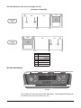
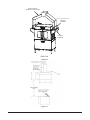
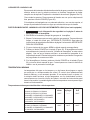
Pant-Leg Vent Connections
Gas heat machines must be provided with a means to exhaust
WKHÀXHJDVHVWRWKHH[WHULRURIWKHEXLOGLQJ
Pant-Leg duct connectors (Fig. 10) alone DO NOT provide ventilation for the gas
ÀXHDWWKHUHDURIWKHPDFKLQH$PLQLYHQWKRRG)LJPXVWEHXVHGRUDFDQRS\
type hood may be used (Fig. 9).
Moist air escapes from each end of the conveyor type dishwasher. The recommended
exhaust requirement is 200 CFM at the entrance end of the dishwasher and 400
CFM at the discharge end. Optional vent hoods or extended hoods may be provided
DWHDFKHQGRIWKHPDFKLQH6XI¿FLHQWPDNHXSDLUPXVWEHSURYLGHGVRWKHH[KDXVW
ÀRZUHVXOWVLQDSRVLWLYHEXLOGLQJSUHVVXUHLQWKHURRPLQZKLFKWKHXQLWLVORFDWHG
(more outside air than exhaust air). Hoods are provided with 4" x 16" vent connectors
with vent dampers which allow adjustment during installation. Typical construction
is for 'Pant-Leg' hood connections to the 4" x 16" vent connectors (Fig. 10). Vent
VWDFNVPXVWEHZDWHUWLJKWDQG¿WLQVLGHWKHYHQWFRQQHFWRURSHQLQJV
If using the 'Pant-Leg' duct, a mini-vent hood (Fig. 11) must be used to vent the
ÀXHJDVHVRQPDFKLQHVXVLQJJDVKHDW7KHPLQLYHQWKRRGPXVWEHSRVLWLRQHG
DPLQLPXPRIDERYHWKHÀXHH[LWDWWKHUHDURIWKHGLVKZDVKHUDQGFRQQHFWHG
WRH[LVWLQJGXFWZRUN7KHYROXPHRIÀXHH[KDXVWLQWKHPLQLYHQWKRRGVKRXOGQRW
exceed 200 CFM.
In either case, if a powered means of exhaust is used, an electrical interlock
PXVWEHSURYLGHGWRDOORZWKHÀRZRIJDVWRWKHGLVKZDVKHUEXUQHURQO\ ZKHQ
the exhaust system is in operation.
For more information, refer to the National Fuel Gas Code, ANSI Z223.1, NFPA54.
In all cases, local codes will prevail.

– 13 –
PANT-LEG DUCT
4” x 16”
VENT
CONNECTOR
EXTENDED
HOOD
CLeN-SERIES
Fig. 10
Fig. 11

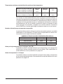
– 14 –
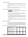
Exhaust Flow Requirements
The following is based on the 2015 International Mechanical Code (IMC):
7KHÀRZ of air required for a vent hood is based on the linear length of the face
of the hood, measured along the front side, parallel with the front of the appliance
UHIHUWR/(1*7+LQ)LJ7KHPLQLPXPQHWDLUÀRZIRU7\SH,,KRRGVXVHGZLWK
dishwashers is 100 CFM per linear foot of hood length. Simply multiply the hood's
OHQJWKLQIHHWWLPHV&)0WRREWDLQWKHUHTXLUHGÀRZUDWH
6XEWUDFWPDNHXSDLUÀRZVXSSOLHGGLUHFWO\WRDKRRGFDYLW\IURPWKHWRWDOH[KDXVW
ÀRZUDWHRIWKHKRRGLIDSSOLFDEOH
For hood designs not covered by these calculations consult the latest edition of the
IMC or other local codes.
ELECTRICAL CONNECTIONS — DISHWASHER
Electrical and grounding connections must comply with the
applicable portions of the National Electrical Code, ANSI / NFPA 70, latest
edition, and / or other local electrical codes.
Disconnect the electrical power to the machine and follow
lockout / tagout procedures. There may be multiple circuits. Be sure all
circuits are disconnected.
Connect a permanent electrical power supply to the terminal block in the control
box on top of the machine. Refer to the machine data plate for proper connection
information and the electrical diagram located inside the control box cover.
CLEARANCE
HEIGHT
LENGTH
Fig. 12

– 15 –
Single-Point Electrical Connection (S.P.E.C.) — Three-Phase Only
All three-phase machines are prewired for single-point electrical connection for the
motors, controls and electric tank heaters; however, electric tank heat machines
WKUHHSKDVHRQO\PD\EH¿HOGZLUHGIRUVHSDUDWHHOHFWULFDOFRQQHFWLRQV5HIHU
to the wiring diagram inside the control box lid. NOTE: The booster heater, when
supplied, is always provided with a separate electrical connection.
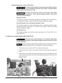
Motor Rotation — Three-Phase Only
Before placing a three-phase machine into service, check to verify that
the conveyor motor rotates in the correct direction. (The control box is pre-wired
at the factory so that all motors are phased together. If the conveyor motor rotation
is correct, the pump motors will also be correct.) Incorrect rotation will result in
unacceptable performance.
To check the conveyor motor's rotation:
Close the machine doors, press POWER on the keypad and allow the machine to
¿OO:KHQWKHPDFKLQHLVFRPSOHWHO\¿OOHGSUHVV32:(5WRWXUQWKHPDFKLQHRII
Disconnect the electrical power to the machine and follow
lockout / tagout procedures. There may be multiple circuits. Be sure all
circuits are disconnected.
Remove the front panel below the doors. Reconnect the electrical power to the
machine, being careful not to touch any uninsulated electrical parts exposed by
removing the front panel. Press START / ENTER on the keypad and verify proper
motor rotation, as follows:
The conveyor motor and clutch must rotate counterclockwise for machines with
right-to-left operation, and clockwise for machines with left-to-right operation.
If the rotation of the conveyor motor is correct, press POWER to turn the machine
off. Disconnect electrical power to the machine, and replace the front panel.
If the conveyor motor does not rotate in the proper direction, disconnect the electrical
power to the machine. At the machine control box on top of the machine, reverse
any two of the incoming power supply leads, either the leads to the entire machine,
or the leads to the motor and controls if they are wired independent of the heaters.
Do not simply reverse the leads to the conveyor motor.
Reconnect the electrical power to the machine. Re-check the conveyor motor's
rotation. The conveyor motor and clutch must rotate counterclockwise for machines
with right-to-left operation, and clockwise for machines with left-to-right operation.
If the rotation of the conveyor motor is correct, press POWER to turn the machine
off. Disconnect the electrical power to the machine. Replace the top cover to the
control box, and replace the front panel.

– 16 –
Optional Equipment Control Connections
Electrical and grounding connections must comply with the
applicable portions of the National Electrical Code, NFPA 70 (latest edition)
and / or other local electrical codes.
Disconnect the electrical power to the machine and follow
lockout / tagout procedures. There may be multiple circuits. Be sure all
circuits are disconnected.
Detergent Feeder
The maximum rating for a detergent dispenser connected to DPS1 and DPS2 is
1.5 amps at line voltage. Refer to Chemical Feeder Installations, page 8.
Rinse Aid Feeder and / or Chemical Sanitizer Feeder
The maximum rating for a rinse aid dispenser and / or chemical sanitizer feeder
connected to RPS1 and RPS2 is 1.5 amps at line voltage. Refer to Chemical
Feeder Installations, page 8.
Vent Fan Control
The maximum rating for a vent fan control connected to VFC1 and VFC2 is 1.5
amps, pilot duty.
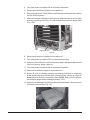
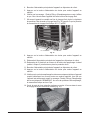
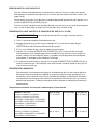
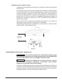
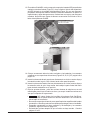
CLeNER and CLeNADV ENERGY RECOVERY SETUP
Disconnect the electrical power to the machine and follow
lockout/tagout procedures. There may be multiple circuits. Be sure all circuits
are disconnected.
Set up procedures must be performed after hot and cold water connections
have been completed, tank(s) are full, and machine is ready for operation.
1. Turn main power to machine OFF at customers disconnect.
2. Ensure tank(s) are empty. If not empty, pull drain lever(s) and allow tank(s) to
drain.
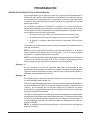
'LVFRQQHFWRQHHOHFWULFDOOHDGDWKRW¿OOVROHQRLGYDOYHFRLOORFDWHGDWWKHWRS
rear of unit by sliding the coil cover off and disconnecting one of the coil wires
(Figs. 13 & 14).
Fig. 13
SLIDE OFF COVER
Fig. 14
REMOVE
COIL WIRE

– 17 –
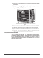
4. Turn main power to machine ON at customers disconnect.
5. Press power button on keypad to turn machine on.
(QVXUHGLVSOD\VKRZV³7DQNV)LOOLQJ´DQGWKDWZDWHULVÀRZLQJLQWRWKHPDFKLQH
WKUXWKH¿QDOULQVHDUPV
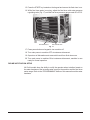
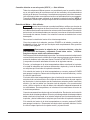
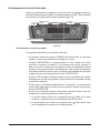
:KLOHWKHPDFKLQHLV¿OOLQJWKUXWKH¿QDOULQVHDGMXVWWKH¿QDOULQVHKRWZDWHU
SUHVVXUHUHJXODWLQJYDOYH)LJXQWLOWKH¿QDOULQVHSUHVVXUHJDXJHUHDGV
20 ± 5 PSI.
8. Press power button on keypad to turn machine off.
9. Turn main power to machine OFF at customers disconnect.
5HFRQQHFWWKHKRW¿OOYDOYHFRLOZLUHUHPRYHGLQVWHSDQGUHSODFHWKHVROHQRLG
valve coil cover by sliding it back on.
11. Turn main power to machine ON at customers disconnect.
12. Press power button on keypad to turn machine on.
(QVXUH¿OOF\FOHLVRSHUDWLQJFRUUHFWO\DQGDOORZWKHPDFKLQHWRFRPSOHWHO\
¿OOWKHWDQNVDQGHQWHUWKH,GOHPRGH³7DQNV)LOOLQJ´VKRXOGQRORQJHUEH
GLVSOD\HGRQFHWKHXQLWLVFRPSOHWHO\¿OOHGNOTE: 'XULQJWKLV¿OOSURFHVV
the pressure gauge should read approximately 5 PSI.
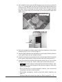
2SHQGRRURIGLVKZDVKHUDQGLQVHUWDGLVKUDFNXSVLGHGRZQLQ¿QDOULQVH]RQH
WRDFWLYDWH¿QDOULQVHÀRZ)LJ
COLD WATER PRVHOT WATER PRV
Fig. 15
Fig. 16

– 18 –
3UHVVWKH67$57NH\ORFDWHGRQWKHNH\SDGDQGHQVXUHWKH¿QDOULQVHLVRQ
:KLOH¿QDOULQVHZDWHULVUXQQLQJDGMXVWWKH¿QDOULQVHFROGZDWHUSUHVVXUH
UHJXODWLQJYDOYH)LJXQWLOWKH¿QDOULQVHSUHVVXUHJDXJHUHDGV36,
17. Press power button on keypad to turn machine off.
18. Turn main power to machine OFF at customers disconnect.
2SHQGRRURIGLVKZDVKHUDQGUHPRYHGLVKUDFNIURP¿QDOULQVH]RQH
20. Turn main power to machine ON at customers disconnect; machine is now
ready for normal operation.
DELIME NOTIFICATION SETUP
All CLeN models have the ability to notify the operator when to delime based on
WKHZDWHUKDUGQHVVRIWKHLQFRPLQJZDWHUVXSSO\WRWKHPDFKLQHDQGWKH¿QDOULQVH
ZDWHUXVDJH5HIHUWRWKHµ352*5$00,1*¶VHFWLRQRIWKLVPDQXDOWRVHWWKHZDWHU
hardness.
Fig. 17
COLD WATER PRVHOT WATER PRV

– 19 –
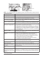
OPERATION
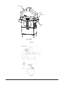
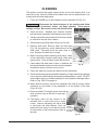
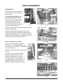
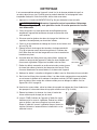
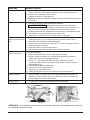
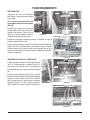
PREPARATION
Make sure the dishwasher is clean
and all parts are in place.
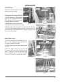
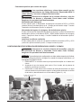
If Equipped with Scrapper (PS/CS)
Install the standpipe in the scrapper
tank (Fig. 18). Standpipe with strainer
)LJJRHVLQWKH¿UVWWDQNZKHUH
the rack enters the machine.
Install the rear and side strainer pans
and lower the strainer bucket (Fig. 20).
Install the upper wash arm (Fig. 19) and the lower wash arm
(Fig. 20) in the scrapper with all end caps. Push arm onto the
connector pipe so the opposite end is held by the guide; then
lift or lower into position.
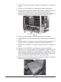
Wash / Rinse Tanks
Install the standpipe(s) in the tank(s) (Figs. 18
and / or 21). Standpipe without strainer (Fig.
21) goes in second / third tank.
Install the strainer pan and the strainer bucket
(Fig. 23).
Install the upper wash arm (Fig. 22) and
the lower wash arm (Fig. 23) with all end
caps. Push arm onto the connector pipe
so the opposite end is held by the guide
(Figs. 22, 23); then lift or lower into position.
Fig. 21 Fig. 22
CONNECTOR
PIPE
WASH ARM
GUIDE
LATCH
END
CAPS
Fig. 23
STRAINER
PAN
STRAINER
BUCKET
WASH ARM
GUIDE
CONNECTOR PIPE
END CAPS
Fig. 18
Fig. 19
END CAPS
PREWASH ARM
CONNECTOR PIPE
GUIDE
LATCH
Fig. 20
STRAINER
PANS
CONNECTOR
PIPE
STRAINER
BUCKET
PREWASH ARM
GUIDE
STANDPIPE
STRAINER

– 20 –
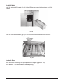
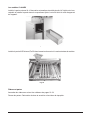
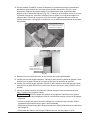
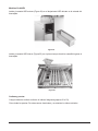
CLeNADV Models
Install the external ASR basket (Fig. 24) in the ASR housing located at the entrance end of the
machine.
,QVWDOOWKHLQWHUQDO$65EDVNHW)LJLQWKH¿UVWWDQNZKHUHWKHUDFNHQWHUVWKHPDFKLQH
Curtains & Doors
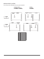
Hang all curtains according to the appropriate curtain diagram (pages 21 – 23).
Close all doors: This lowers and seats the standpipe(s).
Fig. 24
Fig. 25
La page est en cours de chargement...
La page est en cours de chargement...
La page est en cours de chargement...
La page est en cours de chargement...
La page est en cours de chargement...
La page est en cours de chargement...
La page est en cours de chargement...
La page est en cours de chargement...
La page est en cours de chargement...
La page est en cours de chargement...
La page est en cours de chargement...
La page est en cours de chargement...
La page est en cours de chargement...
La page est en cours de chargement...
La page est en cours de chargement...
La page est en cours de chargement...
La page est en cours de chargement...
La page est en cours de chargement...
La page est en cours de chargement...
La page est en cours de chargement...
La page est en cours de chargement...
La page est en cours de chargement...
La page est en cours de chargement...
La page est en cours de chargement...
La page est en cours de chargement...
La page est en cours de chargement...
La page est en cours de chargement...
La page est en cours de chargement...
La page est en cours de chargement...
La page est en cours de chargement...
La page est en cours de chargement...
La page est en cours de chargement...
La page est en cours de chargement...
La page est en cours de chargement...
La page est en cours de chargement...
La page est en cours de chargement...
La page est en cours de chargement...
La page est en cours de chargement...
La page est en cours de chargement...
La page est en cours de chargement...
La page est en cours de chargement...
La page est en cours de chargement...
La page est en cours de chargement...
La page est en cours de chargement...
La page est en cours de chargement...
La page est en cours de chargement...
La page est en cours de chargement...
La page est en cours de chargement...
La page est en cours de chargement...
La page est en cours de chargement...
La page est en cours de chargement...
La page est en cours de chargement...
La page est en cours de chargement...
La page est en cours de chargement...
La page est en cours de chargement...
La page est en cours de chargement...
La page est en cours de chargement...
La page est en cours de chargement...
La page est en cours de chargement...
La page est en cours de chargement...
La page est en cours de chargement...
La page est en cours de chargement...
La page est en cours de chargement...
La page est en cours de chargement...
La page est en cours de chargement...
La page est en cours de chargement...
La page est en cours de chargement...
La page est en cours de chargement...
La page est en cours de chargement...
La page est en cours de chargement...
La page est en cours de chargement...
La page est en cours de chargement...
La page est en cours de chargement...
La page est en cours de chargement...
La page est en cours de chargement...
La page est en cours de chargement...
La page est en cours de chargement...
La page est en cours de chargement...
La page est en cours de chargement...
La page est en cours de chargement...
La page est en cours de chargement...
La page est en cours de chargement...
La page est en cours de chargement...
La page est en cours de chargement...
La page est en cours de chargement...
La page est en cours de chargement...
La page est en cours de chargement...
La page est en cours de chargement...
La page est en cours de chargement...
La page est en cours de chargement...
La page est en cours de chargement...
La page est en cours de chargement...
La page est en cours de chargement...
La page est en cours de chargement...
La page est en cours de chargement...
La page est en cours de chargement...
La page est en cours de chargement...
La page est en cours de chargement...
La page est en cours de chargement...
La page est en cours de chargement...
-
 1
1
-
 2
2
-
 3
3
-
 4
4
-
 5
5
-
 6
6
-
 7
7
-
 8
8
-
 9
9
-
 10
10
-
 11
11
-
 12
12
-
 13
13
-
 14
14
-
 15
15
-
 16
16
-
 17
17
-
 18
18
-
 19
19
-
 20
20
-
 21
21
-
 22
22
-
 23
23
-
 24
24
-
 25
25
-
 26
26
-
 27
27
-
 28
28
-
 29
29
-
 30
30
-
 31
31
-
 32
32
-
 33
33
-
 34
34
-
 35
35
-
 36
36
-
 37
37
-
 38
38
-
 39
39
-
 40
40
-
 41
41
-
 42
42
-
 43
43
-
 44
44
-
 45
45
-
 46
46
-
 47
47
-
 48
48
-
 49
49
-
 50
50
-
 51
51
-
 52
52
-
 53
53
-
 54
54
-
 55
55
-
 56
56
-
 57
57
-
 58
58
-
 59
59
-
 60
60
-
 61
61
-
 62
62
-
 63
63
-
 64
64
-
 65
65
-
 66
66
-
 67
67
-
 68
68
-
 69
69
-
 70
70
-
 71
71
-
 72
72
-
 73
73
-
 74
74
-
 75
75
-
 76
76
-
 77
77
-
 78
78
-
 79
79
-
 80
80
-
 81
81
-
 82
82
-
 83
83
-
 84
84
-
 85
85
-
 86
86
-
 87
87
-
 88
88
-
 89
89
-
 90
90
-
 91
91
-
 92
92
-
 93
93
-
 94
94
-
 95
95
-
 96
96
-
 97
97
-
 98
98
-
 99
99
-
 100
100
-
 101
101
-
 102
102
-
 103
103
-
 104
104
-
 105
105
-
 106
106
-
 107
107
-
 108
108
-
 109
109
-
 110
110
-
 111
111
-
 112
112
-
 113
113
-
 114
114
-
 115
115
-
 116
116
-
 117
117
-
 118
118
-
 119
119
-
 120
120


Hobart CL44eN Instructions Manual
- Catégorie
- Lave-vaisselle
- Taper
- Instructions Manual
dans d''autres langues
- English: Hobart CL44eN
- español: Hobart CL44eN
Documents connexes
-
Hobart FT1000S-ER-BD Mode d'emploi
-
-
-
-
-
-
-
-
-
Autres documents
-
Gaggenau DF 241 Manuel utilisateur
-
Southbend S36 Series Le manuel du propriétaire
-
Empire DVP36PP32EN-3 Le manuel du propriétaire
-
Raypak XVers L 406L-856L Type H Mode d'emploi
-
Bradford White BMGH1600 Manuel utilisateur
-
Dunkirk DWB Series Installation, Operation & Maintenance Manual
-
-
REMEHA Fusion and Fusion Hybrid Mode d'emploi
-
-
GE GTDX185GDCC Guide d'installation