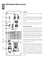
Q-ACOUSTICS 1000I Le manuel du propriétaire
- Catégorie
- Haut-parleurs de la barre de son
- Taper
- Le manuel du propriétaire

User Manual and
Product Specifications
01 00 i Series
EN
FR
IT
ES
DE
EL
ZH
RU


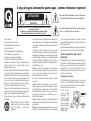
Readtheseinstructions. When a cart is used, use caution when moving the cart/ apparatus
combinationto avoidinjury fromtip-over.
Keepthese instructions.
Unplug this apparatus during lightning storms or when unused for
Heedall warnings.
longperiods oftime.
Important notice to UK users
Followall instructions.
Referall servicingtoqualifiedservicepersonnel. Servicingis required
The appliance cord is terminated with a UK approved mains plug
Donot usethis apparatusnear water.
when the apparatus has been damaged in any way, such as power
fitted with a5A fuse. If
Cleanonly withdry cloth.
supply cord or plug is damaged, liquid has been spilled or objects
Donot blockany ventilationopenings.
have fallen into the apparatus, the apparatus has been exposed to
Installin accordancewith themanufacturer's instructions.
rainor moisture,doesnot operatenormally,or hasbeendropped.
Do notinstall near anyheat sources suchas radiators, heatregisters,
Warning:Toreducethe risk of fire or electrical shock, do not expose
stoves,or otherapparatus (includingamplifiers) thatproduce heat.
this product to rain or moisture. The product must not be exposed to
Do not defeat the safety purpose of the polarized or grounding type
dripping and splashing and no object filled with liquids such as a
plug. A polarizedplughas two blades with one widerthanthe other.
vaseof flowers shouldbe placedon theproduct.
A grounding type plug has two blades and a third grounding prong.
No naked flame sources such as candles should be placed on the
The wider bladeorthe third prong are provided for yoursafety.If the
product.
provided plug does not fit into your outlet, consult an electrician for
Warning: The mains power switch for the subwoofer is the device
replacementof theobsolete outlet.
used to disconnect the unit from the mains supply. This switch is
Protectthe power cord frombeing walked on or pinched,particularly
located on the rear panel. To permit free access to this switch, the
at plugs, convenience receptacles, and the point where they exit
apparatusmust belocatedin anopen areawithout anyobstructions,
fromthe apparatus.
andthe switchmust befreely operable.
Useonly attachments/accessoriesspecified bythe manufacturer.
Caution: Changes or modifications not expressly approved by the
Useonly withacart, stand,tripod, bracket,or table
manufacturercould voidthe user'sauthority tooperate thisdevice.
specified by the manufacturer, or sold with the
apparatus.
mainService Agentsfor theUK arelisted inthis manual.
Third parties: In the unlikely event that youpassthis product on to
athird party,include theseoperating instructionswith theproduct.
Service: Equipmentfor sevicing shouldbe returned tothe supplying
dealer, or to the service agent for your area. The addresses of the
the fuse needsto be replaced, an ASTAor BSI
approved BS1362 fuse rated at 5A must be used. If you need to
change the mains plug, remove the fuse and dispose of this plug
safelyimmediately aftercutting itfrom thecord.
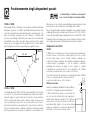
Connecting a mains plug
The wires in the mains lead are coloured in accordance with the
code: Blue:NEUTRAL; Brown:LIVE:
As these colours may not correspond to the coloured markings
identifyingthe terminalsin yourplug, proceedas follows:
The BLUE wire must be
connected to the
terminal marked with
the letter N or coloured
BLUE or BLACK. The
BROWN wire must be
connected to the
terminal marked with
theletter Lor colouredBROWN orRED.
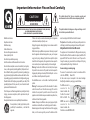
CAUTION!
RISK OF ELECTRIC SHOCK
DO NOT OPEN
TO REDUCE THE RISK OF ELECTRIC SHOCK DO NOT REMOVE COVER (OR BACK)
NO USER-REMOVEABLE PARTS INSIDE
REFER SERVICING TO QUALIFIED PERSONNEL
This symbol indicates that there are important operating and
maintenanceinstructions intheliterature accompanyingthis unit.
This symbol indicates that dangerous voltage constituting a risk of
electricshock ispresentwithin thisunit.
5A FUSE
BS 1362
BROWN
(Live)
BLUE
(Neutral)
Important Information- Please Read Carefully

DO NOT connect your loudspeaker terminals to the mains supply.
Introduction
DO NOT expose your loudspeakers to excessive cold, heat, humidity or
The Q Acoustics 1000i series is a range of loudspeakers designed to meet
sunlight.
the highest expectations of dedicated 2-channel audiophiles and
discerningmovie enthusiasts. The range comprises:
If you play your loudspeakers without their grilles on, be careful to protect
the drive units from damage.
1010i: Compact Bookshelf speaker with a 100 mm bass driver.
DO NOT use makeshift stands. Fit the Q-Acoustics approved stand
1020i: Bookshelf speaker with a 125 mm bass driver.
according to the instructions and using any fixings provided. Your dealer
1030i: Compact Floorstander with a 165 mm bass driver
will advise you.
1050i: Floorstander with two 165 mm bass drivers
DO NOT dismantle the loudspeaker. You will invalidate the warranty.
1000Ci: Centre channel with two 100 mm bass drivers, which can be wall
mounted if required.
Unpacking your loudspeakers
1000Si: 100 Watt active subwoofer with a 200 mm driver and signal
Unpack the speakers fully. Lift the speakers from the cartons by holding
sensing for automatic power on/off.
the cabinets. Do not use the polythene bags to lift them. The 1030i, 1050i,
and 1000Si are heavy - get assistance to lift them if necessary.
All the passive speakers are bi-wireable with the exception of the 1010i
and 1000Ci.
When manoeuvring loudspeakers, do not drag them across the floor as
this may cause damage - lift them before moving them.
All the loudspeakers may be operated close to TV monitors with no ill-
effects with the exception of the 1000Si, which should not be operated
In the carton you will find: The loudspeaker/s and this product manual.
within 500mm of TV screens monitors or other magnetically sensitive
In addition the packing for the following models contains:
equipment. Plasma and LCD screens are unaffected.
1030i and 1050i: A plinth for each speaker, screws, an Allen key to
Before making any connections to your loudspeakers make sure that all
attach the stand and a set of floor spikes and spike covers.
active units in your system are switched off at the mains.
1010i, 1020i, 1000Ci: A set of four adhesive feet.
When switching on your sound system or changing input sources, set the
1000Si: An IEC power cord suitable for the mains supply in your area.
main volume control at a low level. Turn up the level gradually.
Check the product carefully. If any items are damaged or missing, report
NEVER play your sound system at full volume. The position of the
this to your dealer as soon as possible.
volume control is deceptive and does not indicate the power level of the
Retain the packing for future transport. If you dispose of the packing,
system. Using very high volume settings may damage your hearing.
please do so following all recycling regulations in your area.
Q Acoustics 1000i Series

Fitting the Floor Stand and Spikes- 1030i and 1050i Sand Filling the 1030i
Place a soft cloth or towel on the The lower chamber of the 1030i can be filled with sand to aid stability and
floor. Invert the loudspeaker and to dampen acoustic vibration. This is entirely at your option. No harm is
place it on the cloth. caused if you omit this procedure.
You will need:
The stand consists of a base and a
pillar. Attach the base to the pillar
l5kg of dry sand - play sand
with the five short screws. An Allen is ideal. Do not use
key is provided so you can tighten building sand.
the screws properly.
lA large, strong polythene
bag.
Invert the stand and thread the four
long bolts through the base and
lA dry pouring jug.
the pillar; line up the bolts with the
Remove the bung in the rear
mounting holes in the bottom of
panel. Push the bag into the
the speaker and tighten securely.
chamber with the mouth of
the bag protruding at least
Make sure the recess in the stand
100 mm. Carefully pour (or
faces the rear of the loudspeaker.
spoon) the sand into the bag.
Thread the spikes half way into the
When all the sand is in the
base and return the loudspeaker to
bag tie the mouth securely
the upright position. (If you have a
and push the bag into the
wood or stone floor push a spike
chamber. Replace the bung.
protector over each spike before
turning the speaker upright)
1010i, 1020i,1000Ci
When the speaker is the right way
Each loudspeaker is
up, insert the Allen key into each
provided with four adhesive feet. If you are not wall mounting the
spike from the top and adjust all
speakers, peel the backing off each foot and press a foot into place at
the spikes in and out until the
each corner of the bottom panel 15 mm in from each edge.
loudspeaker is level and stable.
Spikes are sharp. Exercise care!
Never place a spiked loudspeaker where it can cause damage!
Always move your loudspeakers by lifting them - never drag them!
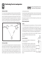
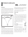
Preparation

mounting is also possible.
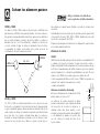
1030i and 1050i
An optional bracket designed specifically to wall mount the Q Acoustics
The 1030i and 1050i loudspeakers should be positioned at least 200mm
1010i, 1020i and 1000Ci is available from your dealer. Floor stands for the
from a back wall and 500mm from the side walls. Placing the speakers
1010i and 1020i are also available.
closer to the wall will increase bass but could cause the sound to boom
and lack precision and detail. The speakers should be 2m - 4m apart and
Be prepared to experiment to find the best setup for your taste in your
central to the seated listener. Turning the speakers slightly inwards will
particular listening room.
sharpen a stereo image but may cause narrowing of the sound source.
Effects loudspeakers
1000Ci
The 1000Ci is designed to be operated close to a TV screen and central
to it. It should be placed immediately above or below the screen. If you
are using a regular TV set, make sure that the TV is capable of adequately
supporting the speaker and has a level top. If not, consider placing the TV
on a cabinet with the 1000Ci on a secure shelf immediately below the TV.
If you have a Plasma or LCD monitor, mount the 1000Ci to the wall or
other suitable surface immediate ly above or below
the screen.
Surround Speakers
There are recommendations from Dolby labs for
5.1 effects speakers.
1010i and 1020i
Surround speakers should be mounted on either
The 1010i and 1020i are ideally mounted on Q-Acoustics floor stands or
side of the listener, slightly behind the listening
wall mounted. If you are stand mounting, a simple guide is that the treble
position. The speakers should be sited facing
unit should be at ear level to a seated listener. Wall mounted speakers
inward either mounted on the side walls of the
may be mounted slighter higher with the speaker angled down. Stand
room or if the room is large, on high stands and
mounted speakers should be treated as floorstanding speakers except
with their centres above ear level to a seated
that the speaker may be placed a little closer to the back wall. Shelf
listener.
Positioning Passive Loudspeakers
2m-4m
2m-4m
>500mm
>200mm
0-30°
400mm
Dolby and the double-D symbol are
trade marks of Dolby Laboratories.

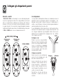
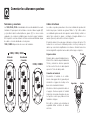
Terminals and Connectors Loudspeaker Cables
The 1020i, 1030i and 1050i are bi-wireable. A bi-wireable crossover has Specialist loudspeaker cables will offer a higher standard of
four terminals. The upper pair of terminals connects to the treble (HF) reproduction than general purpose ‘bell’ or ‘zip’ wire. Use cable with
speaker and the lower pair to the bass (LF) speaker/s. As supplied the generous amounts of copper for the front and centre channels. Thin
crossovers are fitted with removable links to connect the terminal pairs. cables reduce the bass and restrict the dynamic range. Surround (rear)
This permits you to connect the loudspeaker conventionally using one channels are less critical.
pair of cables or in bi-wired mode with two pairs.
Speaker cable has a stripe or tracer along one core. By convention this is
The 1010i and 1000Ci have standard two terminal crossovers. connected to the positive terminals. The cables connecting the amplifier
to the front loudspeakers should ideally be the same length. Never join
cables - use complete lengths.
Preparing Cables
Split the cable to a depth of about 40 mm.
Bare the wire to a depth of 10mm and twist
the ends to gather any stray wires. Crop the
cable leaving 7mm of bare wire exposed.
Connecting a Terminal
Unscrew the terminal anticlockwise to
expose the mounting hole in the base of the
terminal column.
Insert the bare end of the cable into the hole.
Re-tighten the terminal fully hand tight. Make
sure there are no stray wires which could
touch adjacent terminals.
In the EU it is against safety regulations to
use 4mm loudspeaker plugs.
.
1020i, 1030i, 1050i
Standard
Connection
Bi-Wired
Connection
1010i, 1000Ci
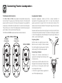
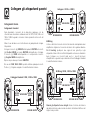
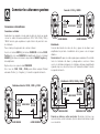
Connecting Passive Loudspeakers
Tight
Loose
30mm
7mm

Stereo Connections
Standard Connections
Each loudspeaker is provided with a cable guide so you can dress the
cables neatly. The 1010i, 1020i, 1030i and 1050i and 1000Ci have the
guide fitted at the bottom of the crossover terminal panel.
Bi-Wiring
Thread the cable up through the guide before connecting the
loudspeaker.
Directly connecting the treble and bass networks of a loudspeaker to an
amplifier improves both bass performance and dynamic range.
Connect the RED (+) terminal of the RIGHT loudspeaker to the RED,
Positive (+) terminal on the RIGHT channel of the amplifier. Connect the
To bi-wire: Prepare two twin cables for each loudspeaker. Unscrew all
BLACK (–) terminal of the loudspeaker to the matching BLACK,
the loudspeaker terminals and remove both links. Now connect the
Negative (–) terminal of the amplifier.
treble terminals and the bass terminals to the amplifier following the
procedure described in Standard Wiring. Refer to the illustration below.
Repeat this procedure for the LEFT channel.
In the case of the 1020i, 1030i and 1050i you may use any convenient
Positive(+) or Negative (–) terminal. Refer to the illustration below.
ii
When your speakers are connected: Switch on the system and play
some music at moderate level. Fine tune the speaker placement to suit.
Connecting Passive Loudspeakers
RIGHT
SPEAKER
LEFT
SPEAKER
Standard Wiring: 1020i, 1030i and 1050i
Bi-Wiring: 1020i, 1030i and 1050i
RIGHT SPEAKER LEFT SPEAKER
RIGHT SPEAKER LEFT SPEAKER
AMPLIFIER
AMPLIFIER
Connecting the 1010i and 1000Ci
RIGHT SPEAKER LEFT SPEAKER
AMPLIFIER
RIGHT
SPEAKER
LEFT
SPEAKER
RIGHT
SPEAKER
LEFT
SPEAKER

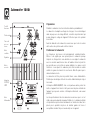
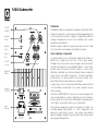
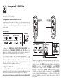
1000i Subwoofer
Preliminaries
Unpack the subwoofer following the guidelines given earlier.
The subwoofer is set to the voltage in your area. If you move to an area
with a different voltage, take the unit to a qualified technician to have the
voltage changed. This is something that you should not do yourself.
Before connecting the subwoofer please make sure that all the active
units in your system are switched off at the mains.
Positioning the Subwoofer
Bass frequencies are substantially omnidirectional. Although this means
that you can position the subwoofer almost anywhere, the stereo image
will still benefit by siting the subwoofer level with the front loudspeakers
and as central to the listening position as possible. This may not be
feasible in a multichannel system. If you place the subwoofer close to a
wall the bass will be re-inforced though in some locations the bass may
be boomy and indistinct. Do not place the subwoofer across a corner.
The subwoofer should be positioned close to a mains power source. Do
not use extension cables. Purchase a longer power cord if necessary.
The MAINS ON/OFF switch is the means of disconnecting this apparatus
from the mains and is mounted on the rear panel. There should be ample
free space between the rear of the cabinet and any wall or other object to
allow free unrestricted access to this switch.
When siting the subwoofer ensure the floor is sound with no loose
floorboards etc. The air movement from the subwoofer at high volumes is
substantial - do not place it close to soft furnishings or objects that may
rattle. Do not place objects of any kind on the unit.
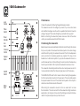
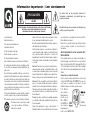
Phase
Switch
Line
Input
ON/OFF
Switch
Mains
Input
Level
Control
Crossover
Control
Speaker
Inputs
Power
Indicator
220V/240V-50Hz
Fuse Type: T 1AL/250V
110V/120V-60Hz
Fuse Type: T 2AL/250V
MAX 100 W AT TS
000 Powered Sub Woofer
1
i
S

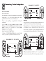
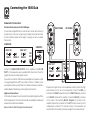
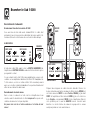
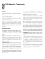
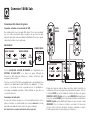
Subwoofer Connections
Standard Connection via the AV SUB Input
You will need a single RCA phono interconnect. As this cable is likely to
be quite long, make sure you get a good quality fully screened cable.
Your Q Acoustics dealer will be happy to supply you with a suitable
interconnect.
Connect the SUBWOOFER OUTPUT on the amplifier to the AV SUB
INPUT on the subwoofer using a suitable RCA interconnect. Push the
plugs firmly home to ensure a good contact.
If you wish to connect the 1000i Sub to a preamplifier or a spare line output
on a regular amplifier, do NOT use a Stereo to Mono ‘Y’ adaptor or your
sound system will be set into Mono! Your dealer will advise you about a
Prepare two lengths of twin core loudspeaker cable. Unscrew the high
suitable adaptor. Alternatively, use the High Level connection.
level terminals on the rear of the subwoofer. Connect the RED (+)
High Level Connections
terminal on the RIGHT subwoofer input to the RED, Positive (+) terminal
In this mode the subwoofer is connected to the amplifier together with the
on the RIGHT channel of the amplifier. Connect the BLACK (–) terminal
Front loudspeakers. This connection should be used only if a dedicated
on this input to the matching BLACK, Negative (–) terminal on the
subwoofer line output is unavailable.
amplifier. Repeat this procedure for the LEFT channel. Leave the front
loudspeakers connected. The internal circuitry of the subwoofer will
Never connect to both the high and line level inputs!
combine the front channels to produce a single common bass channel.
SUB
OUT
RIGHT
LEFT
REAR LS FRONT LS
CENTRE LS
RIGHT
LEFT
AV AMPLIFIER
SUBWOOFER
RIGHT
LEFT
REAR LS
CENTRE LS
RIGHT
LEFT
FRONT LS
AV AMPLIFIER
RIGHT SPEAKER LEFT SPEAKER
SUB.
Connecting the 1000i Sub

As always the final settings should be determined by listening. You
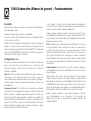
Switching On
should listen to a wide range of music at different volume settings while
Check that all system connections are properly and securely made.
doing the setup.
Ensure that the subwoofer is switched off.
When setting up the subwoofer, always bear in mind that the human ear’s
Set the subwoofer level control roughly halfway. Set the crossover control
sensitivity to bass varies enormously with the volume level, hence the
to 70Hz.
need for a wide range of programme material and sound levels.
Plug the supplied power cord into the subwoofer and then into the mains
point. Switch on the power at the mains point and then switch the
Phase: The phase switch should be initially set at 0º. As room acoustics
ON/OFF switch on the subwoofer to ON. The POWER light on the
and placement are important at very low frequencies the phase may
subwoofer rear panel will glow and the subwoofer is operational.
need to be set to 180º. One setting will offer fuller and more extended
bass than the other. As the effect can be quite subtle, especially with
Setting Up and Use
small loudspeakers where relatively more bass is coming from the
As there is a close relationship between the subwoofer volume, its
subwoofer, extended listening and experimentation may be necessary
physical position and the crossover frequency, mutual adjustments to all
before the final decision is made.
three may be necessary before the system is fully set up.
Auto Power On: This feature enables you to switch the main system on
Level: The Level Control sets the volume of the subwoofer relative to the
and off without having to remember to switch the subwoofer on and off as
other speakers in the system. Set a level that enhances the bass of the
well.
system. There should be a seamless blend between the front speakers
The 1000Si has a built in level sensor. If there is no input, after a short time
and the subwoofer. If you can hear the subwoofer it’s too loud!
the subwoofer will automatically power down into Standby mode. This is
Crossover frequency: Set the crossover control according to the size
indicated by the POWER light on the rear panel changing to red. As soon
and low frequency extension of the front speakers. The role of the
as the subwoofer senses an input it will automatically switch into
subwoofer is to extend the bass response of the system and not to
operational mode and the power light will again glow green.
increase the overall bass level. If the loudspeakers are large, a value
Although the subwoofer can be safely be left in standby mode
between 50 and 60 Hz is probably about right. With smaller speakers
indefinitely, if you are going to be absent from home for a long period, we
such as the 1010i, this can be increased as far as 90Hz. At higher settings
advise that the unit be switched off at the ON/OFF switch.
the subwoofer may become intrusive and low level detail and definition
may suffer.
1000i Subwoofer - Operation

SUB
OUT
RIGHT
LEFT
FRONT LS
CENTRE
RIGHT
LEFT
SUBWOOFER
AV AMPLIFIER
REAR LS
RIGHT FRONT
LEFT FRONT
RIGHT SURROUND
LEFT SURROUND
CENTRE
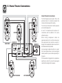
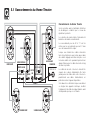
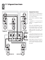
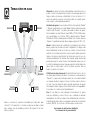
5.1 Home Theatre Connections
Home Theatre Connections
The Front Speakers are bi-wired. This is the
preferred mode of connection provided the
crossover network supports bi-wiring.
The Centre and Surround channel speakers
are conventionally wired.
6.1 and 7.1 connections are the same as 5.1
connections with the addition of the extra
effects channel/s.
When running loudspeaker cables be
especially careful not to run them across open
floor areas where they could be a source of
danger. Run loudspeaker cables around room
boundaries whenever possible.
Line level signal cables should be run apart
from mains cables. Never run line level signal
cables parallel to power cables especially on
long runs.
If the subwoofer is triggered on by appliances
switching on and off, re-route the input signal
cable before taking further measures.

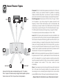
Home Theatre Topics
0º
-
3
0
2
º
º
2
9
0
º
-
1
1
0
º
1
5
0
º
-
1
3
5
º
LEFT
CENTRE
RIGHT
SURR
LEFT
SURR
RIGHT
BACK RIGHT
BACK LEFT
SUB
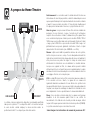
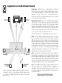
Above is the Dolby Labs recommended layout for 7.1systems.
The 6.1 layout is the same except a single central speaker replaces
the two back units. The 5.1 layout has no back speakers
Placement: The Front and Centre speakers should be in line. If this is not
possible, consult your processor manual for guidance on adjusting
relative centre/front delay times. If you have a 5.1 system, the listening
seat can be closer to the rear wall. As always, be prepared to experiment.
Bass Management: AV processors offer the choice of ‘Large’ or ‘Small’
for the speakers. If you choose ‘Large’ the speaker receives the full
frequency. Choose ‘Small’ and the bass is sent to the Subwoofer. We
recommend you choose ’Small’ for the 1000Ci and the 1010i and 1020i
wherever they are used in the system. The 1050i should be set to ‘Large’.
The 1030i would normally be set to ‘Large’ but you may set it to ‘Small’
The subwoofer option should be enabled (set to ‘ON’ or ‘YES’)
Levels: When the basic system parameters have been established, put
your processor into the ‘setup’ routine. Set up each individual speaker so
that the level is the same at the listening position as all the others. If your
processor enables you to adjust the delay times, follow the instructions
closely as this will profoundly affect the final result. When you play a
movie you may think the rear channels are too soft - they aren’t! You may
however have to adjust the subwoofer level both at the processor and at
the subwoofer. Once set, do not re-adjust these levels.
LFE: The LFE channel sends all the bass sound effects to the subwoofer.
If speakers are set to ‘Small’ , system bass from those channels is also
sent to the subwoofer. If you play the system at extreme levels and/or
have the subwoofer level set too high you may overdrive the subwoofer
with unpleasant sonic results. If this occurs, reduce the level
immediately.
Phase: If your speakers are incorrectly wired the bass will be blurred and
thin. In this case, check the wiring carefully. If your speaker wire has a
tracer along one core, consistently use the striped core to connect all the
positive (RED) terminals. In this way the system will always be in phase.
Always follow the instructions in your AV processor manual!

Cabinet Care
Q Acoustics loudspeakers are warranted free of defects in materials and
workmanship as follows:
Clean cabinets with a barely damp cloth. The finish is sealed with a high
quality sealant so that in normal use there is no need to use solvent
Passive Loudspeakers: 5 years from the date of purchase
based cleaning materials. If the cabinets become stained, remove the
Active Loudspeakers & Subwoofers: 2 years from the date of purchase
stain with a cloth lightly moistened with water, white spirit or isopropyl
During the warranty period Q Acoustics will, at its option, repair or
alcohol depending on the stain. Then lightly buff with a cloth to remove
replace any product found to be faulty after inspection by the company
any residue of the cleaning agent. Never use abrasives of any kind.
or its appointed distributor or agent.
Grilles
Misuse and fair wear and tear are not covered by warranty.
Lightly brush out grilles with a soft brush. Do not remove the speaker
Goods for repair should in the first instance be returned to the supplying
grilles unless absolutely necessary.
dealer. If this is not possible the item/s should be sent carriage paid
preferably in the original packing, to Q Acoustics or their appointed
Drive Units.
distributor for your area and accompanied by proof of purchase.
Drive units are best left untouched as they are easily damaged when
Damage sustained by goods in transit to the repair centre is not covered
exposed.
by warranty. Return carriage will be paid by Q Acoustics or their
distributor as appropriate.
This warranty does not in any way affect your legal rights.
Appointed Distributor in the UK:
Armour Home Electronics Ltd
Units 7 & 8, Stortford Hall Industrial Park
Bishops Stortford, Herts, UK
CM23 5GZ
For service information In other countries contact
Care and Cleaning Warranty

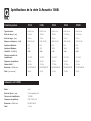
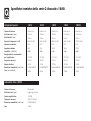
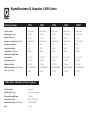
Q Acoustics 1000i Series Specifications
Enclosure type:
Bass Unit (mm):
Treble Unit (mm):
Frequency response: (±3dB):
Nominal Impedance:
Minimum Impedance:
Sensitivity (2.83v@1m):
Recommended amplifier power:
Crossover frequency:
Effective volume:
Cabinet dimensions (HxDxW mm):
Weight (per cabinet):
2-way reflex
100 mm
25 mm
68Hz - 20 kHz
6Ù
4Ù
86dB
15 - 75W
2.5 kHz
3.4 litres
H215 x D195 x W150
2.8 Kg
2-way reflex
125 mm
25 mm
65Hz - 20 kHz
6Ù
4Ù
88dB
25 - 75W
2.8 kHz
7.0 litres
H250 x D265x W175
4.0 Kg
2-way reflex
165 mm
25 mm
48Hz - 20 kHz
6Ù
3.6Ù
90dB
25 - 100W
2.7 kHz
17.7 litres
H900 x D295 x W195
15.5 Kg
2-way reflex
2 x 165 mm
25 mm
44Hz - 20 kHz
6Ù
3.8Ù
92dB
25 - 150W
2.4 kHz
35.7 litres
H975 x D295 x W195
17.8 Kg
2-way reflex
2 x 100mm
25 mm
75Hz - 20 kHz
6Ù
4.7Ù
89dB
25 - 100W
2.8 kHz
5.2 litres
H150 x D195 x W425
5.5 Kg
1010i 1020i 1030i 1050i 1000Ci
Passive Loudspeakers
Enclosure type:
Bass Unit (mm):
Amplifier power:
Crossover frequency:
Cabinet dimensions (HxDxW mm):
Weight :
1000Si Active Subwoofer
Ported
200 mm long throw
100 Watts
45Hz - 175Hz (var.)
H330 x D350 x W320
11.0Kg


EN
FR
IT
ES
DE
EL
ZH
RU
Mode d’emploi et
caractéristiques
techniques du produit
Serie 1000i

Veuillez lire ces instructions.
Veuillez conserver ces instructions.
Veuillez prendre connaissance de tous les avertissements.
Veuillez suivre toutes les instructions.
N’utilisez pas cet appareil à proximité de l’eau.
Nettoyez uniquement avec un chiffon sec.
N’obstruez pas les grilles de ventilation.
Suivez attentivement les instructions du fabricant lors de l’installation.
N’installez pas cet appareil à proximité d’une source de chaleur telle que
des radiateurs, des bouches d’air chaud, des fours, ou tout autre appareil
(y compris des amplificateurs) produisant de la chaleur.
Ne supprimez pas la sécurité apportée par la prise polarisée ou de
type B. Une prise polarisée possède deux broches, dont une plus large
que l’autre. Une prise de type B possède deux broches et une fiche terre.
La broche la plus large ou la fiche terre sont là pour votre sécurité. Si la
prise fournie ne convient pas, adressez-vous à un électricien pour une
mise aux normes de votre installation électrique.
Evitez de marcher sur le cordon d’alimentation ou de le pincer, en
particulier, à l’extrémité du cordon, de la prise et à la sortie de l’appareil.
Utilisez uniquement des accessoires spécifiés par le fabricant.
Utilisez uniquement les chariots, pieds, tripodes,
supports ou les tables recommandés par le fabricant
ou vendus avec l’appareil.
Si vous utilisez un chariot, faites très attention lors du transport de
l’appareil et évitez de le faire tomber pour ne pas vous blesser.
Débranchez cet appareil en cas d’orage ou lorsque vous ne vous en
servez pas pendant une période prolongée.
Pour toute réparation, adressez-vous à un professionnel. Faites réparer
cet appareil pour des dommages de n’importe quelle nature : cordon
d’alimentation abîmé, liquide ou objet introduit dans l’appareil,
exposition à la pluie ou à l’humidité, fonctionnement inhabituel,
chutes diverses.
Avertissement : Afin de diminuer les risques d’incendie ou de choc
électrique, conservez cet appareil à l’abri de la pluie et de l’humidité.
Evitez toute éclaboussure et ne posez pas d’objets contenant des
liquides, comme des vases, sur cet appareil.
Tenir à l’écart des flammes et ne pas poser de bougie sur cet appareil.
Avertissement : L’interrupteur de mise en marche du subwoofer sert à
mettre cette unité hors tension. Cet interrupteur est situé sur le panneau
arrière. Afin de pouvoir accéder librement à cet interrupteur, l’appareil
doit être placé dans un endroit ouvert sans aucun obstacle. L’interrupteur
doit lui aussi être libre d’accès.
Attention : Tout changement, ou modification, non expressément
autorisé par le fabricant annule la garantie.
Réparation : Pour toute réparation, renvoyez l’appareil au fournisseur,
ou au réparateur de votre région; La liste des adresses des réparateurs
au RU figure dans ce manuel.
Tiers : Au cas improbable ou vous revendiez ce produit a un tiers,
veuillez fournir ce mode d’emploi avec le produit.
Remarque importante pour les
utilisateurs au Royaume-Uni
Le cordon d’alimentation possède une prise anglaise contenant un
fusible de 5A. Si le fusible doit être remplacé, utilisez un fusible de 5A
de type ASTA ou BSI à la norme BS1362. Si vous devez changer la prise
elle-même, ôtez le fusible avant de jeter la prise immédiatement après
avoir coupé le cordon d’alimentation.
Branchement sur secteur
Les couleurs des fils du cordon d’alimentation sont en conformité avec
le code suivant : Bleu : NEUTRE; Marron : PHASE.
Ces couleurs ne correspondant peut être pas à celles des fiches de votre
prise, procédez comme suit :
Connectez le fil BLEU
à la borne affichant la
lettre N ou de couleur
BLEUE ou NOIRE.
Connectez le fil
MARRON à la borne
affichant la lettre L ou
de couleur MARRON
ou ROUGE.
ATTENTION!
RISQUE DE CHOCS ELECTRIQUES
NE PAS OUVRIR
POUR DIMMINUER LE RISQUE DE CHOCS ELECTRIQUES NE PAS ENLEVER LE BOITIER
(NI LE PANNEAU ARRIERE)
AUCUNE PIECE NE PEUT ETRE ENLEVEE PAR L’UTILISATEUR À L’INTERIEUR
CONSULTER UN PROFESSIONEL QUALIFIE POUR TOUTE REPARATION
Ce symbole indique des instructions d’utilisation et d’entretien
essentielles dans la documentation qui accompagne cet appareil.
Ce symbole indique la présence dans cet appareil d’un voltage
dangereux, qui peut poser un risque de choc électrique.
B
S
1
362
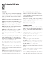
Informations importantes – Lire attentivement

Série Q Acoustics 1000i
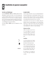
Introduction
La gamme d’enceintes de série Q Acoustics 1000i est conçue pour
répondre aux besoins des cinéphiles et des amateurs de musique. Notre
gamme comprend :
1010i : Une enceinte d’étagère compacte avec un caisson de basses de
100 mm.
1020i : Une enceinte d’étagère avec un caisson de basses de 125 mm.
1030i : Une enceinte colonne avec un caisson de basses de 165 mm.
1050i : Une enceinte colonne avec deux caissons de basses de 165 mm
1000Ci : Une enceinte centrale avec deux caissons de basses de 100
mm, pouvant être fixée au mur, si nécessaire.
1000Si : Un subwoofer actif de 100 Watt avec un haut-parleur de 200 mm
et un détecteur de signal pour allumage/arrêt automatique.
Vous pouvez effectuer un bi-câblage sur toutes les enceintes passives sauf
la 1010i et la 1000Ci.
Toutes les enceintes fonctionnent à proximité des écrans de télévision sans
aucun problème à l’exception des enceintes de la gamme 1000Si, qui ne
doivent pas être placées à moins de 500 mm d’écrans de télévision ou de
tout autre matériel pouvant être perturbé par un champ magnétique. Cela
n’affecte pas les écrans à plasma ni les écrans à affichage à cristaux
liquides.
Avant de brancher vos enceintes, assurez-vous que toutes les parties
actives de votre système audio sont éteintes ou hors tension.
Lorsque vous allumez votre système audio ou lorsque vous changez les
sources d’entrée, baissez le volume jusqu’à un bas niveau. Montez
graduellement le son.
Ne montez JAMAIS le son au maximum. Le bouton de contrôle du volume
est trompeur et n’indique pas la puissance du système audio. L’utilisation
du volume au maximum peut endommager votre capacité auditive.
Ne raccordez PAS les bornes de votre enceinte au secteur.
Ne laissez PAS vos enceintes dans des endroits trop froids, trop chauds,
trop humides ou au soleil.
Si vous utilisez vos enceintes sans les grilles de protection, faites bien
attention à ne pas endommager les haut-parleurs.
N’utilisez PAS des pieds de fortune. Installez vos enceintes sur des pieds
recommandés par Q-Acoustics selon les instructions, en utilisant les
pointes de fixation fournies. Votre revendeur pourra vous conseiller.
NE démontez PAS vos enceintes car vous annuleriez la garantie.
Déballer vos enceintes
Déballez complètement vos enceintes. Sortez les enceintes du carton en
soulevant les enceintes elles-mêmes. Ne vous servez pas de sacs en
polyéthylène pour les soulever. Les enceintes 1030i, 1050i, et 1000Si sont
assez lourdes; demandez de l’aide pour les soulever, si nécessaire.
Lorsque vous déplacez les enceintes, ne les traînez pas par terre car vous
risquez de les endommager. Soulevez-les avant de les déplacer.
Vous trouverez dans le carton : Le(s) enceinte(s) et ce mode d’emploi.
Pour les modèles suivants, le carton d’emballage contient également :
1030i et 1050i : Un socle pour chaque enceinte, des vis, une clef
hexagonale pour fixer le pied et un paquet de pointes de fixation au sol et
de protège-pointes.
1010i, 1020i, 1000Ci : Un paquet de quatre pieds adhésifs.
1000Si : Un cordon d’alimentation C.E.I. adapté à votre pays.
Vérifiez bien le produit. Si l’un des articles est manquant ou endommagé,
contactez votre revendeur dès que possible.
Conservez l’emballage pour transporter le matériel ultérieurement. Si vous
décidez de jeter l’emballage, respectez la réglementation de votre pays en
matière de recyclage.

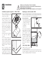
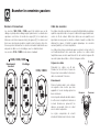
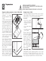
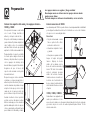
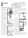
Installation
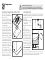
Installation du pied et des pointes – 1030i et 1050i
Placez un chiffon doux ou une
serviette au sol. Retournez l’enceinte
et placez-la sur le chiffon.
Le pied est constitué d’un socle et
d’une colonne. Fixez le socle sur la
colonne à l’aide des cinq vis
courtes. Utilisez la clef hexagonale
pour resserrer les vis correctement.
Retournez le pied et placez les
quatre boulons longs dans le
socle et la colonne. Alignez les
boulons dans les trous prévus en
dessous de l’enceinte et serrez
correctement.
Assurez-vous que le creux du pied
est tourné vers l’arrière de
l’enceinte.
Vissez à moitié les fixations sur le
socle et remettez l’enceinte à
l’endroit. (Si vous possédez un sol
en bois ou en pierre enfoncez les
protège-pointes sur chaque fixation
avant de remettre l’enceinte à
l’endroit).
Une fois l’enceinte à l’endroit,
resserrez chaque fixation avec la
clef hexagonale en partant du haut
et ajustez plus ou moins les
fixations jusqu’à ce que l’enceinte
soit à niveau et parfaitement stable.
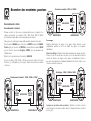
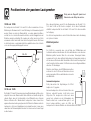
Remplissage au sable du modèle 1030i
Vous pouvez remplir la partie basse du modèle 1030i de sable afin de le
stabiliser et de réduire les vibrations sonores. Cela dépend entièrement de
vous. Si vous ne le faites pas, cela ne l’endommagera pas.
Vous aurez besoin de:
• 5kg de sable sec; du sable
de jeu est idéal. N’utilisez pas
de sable de construction.
• Un grand sac solide en
polyéthylène.
• Un pichet sec.
Otez le bouchon du panneau
arrière. Enfoncez le sac dans
la partie basse de l’enceinte
avec l’ouverture du sac
dépassant d’au moins 100
mm. Versez soigneusement
(ou utilisez une cuiller) le sable
dans le sac. Lorsque le sac est
plein, refermez-le bien et
enfoncez le complètement
dans l’enceinte. Replacez le
bouchon.
1010i, 1020i, 1000Ci
Chaque enceinte est livrée
avec quatre pieds adhésifs. Si
vous décidez de ne pas fixer vos enceintes au mur, ôtez la partie protectrice
des pieds et appuyez sur chaque pied pour le mettre en place dans
chaque coin du panneau inférieur à 15 mm du bord.
Fixations au sol très pointues. Faites très attention !
Ne placez jamais une enceinte avec des pointes de fixation dans des
endroits pouvant être endommagés !
Soulevez toujours vos enceintes pour les déplacer; ne les tirez jamais !
La page est en cours de chargement...
La page est en cours de chargement...
La page est en cours de chargement...
La page est en cours de chargement...
La page est en cours de chargement...
La page est en cours de chargement...
La page est en cours de chargement...
La page est en cours de chargement...
La page est en cours de chargement...
La page est en cours de chargement...
La page est en cours de chargement...
La page est en cours de chargement...
La page est en cours de chargement...
La page est en cours de chargement...
La page est en cours de chargement...
La page est en cours de chargement...
La page est en cours de chargement...
La page est en cours de chargement...
La page est en cours de chargement...
La page est en cours de chargement...
La page est en cours de chargement...
La page est en cours de chargement...
La page est en cours de chargement...
La page est en cours de chargement...
La page est en cours de chargement...
La page est en cours de chargement...
La page est en cours de chargement...
La page est en cours de chargement...
La page est en cours de chargement...
La page est en cours de chargement...
La page est en cours de chargement...
La page est en cours de chargement...
La page est en cours de chargement...
La page est en cours de chargement...
La page est en cours de chargement...
La page est en cours de chargement...
La page est en cours de chargement...
La page est en cours de chargement...
La page est en cours de chargement...
La page est en cours de chargement...
La page est en cours de chargement...
La page est en cours de chargement...
La page est en cours de chargement...
La page est en cours de chargement...
-
 1
1
-
 2
2
-
 3
3
-
 4
4
-
 5
5
-
 6
6
-
 7
7
-
 8
8
-
 9
9
-
 10
10
-
 11
11
-
 12
12
-
 13
13
-
 14
14
-
 15
15
-
 16
16
-
 17
17
-
 18
18
-
 19
19
-
 20
20
-
 21
21
-
 22
22
-
 23
23
-
 24
24
-
 25
25
-
 26
26
-
 27
27
-
 28
28
-
 29
29
-
 30
30
-
 31
31
-
 32
32
-
 33
33
-
 34
34
-
 35
35
-
 36
36
-
 37
37
-
 38
38
-
 39
39
-
 40
40
-
 41
41
-
 42
42
-
 43
43
-
 44
44
-
 45
45
-
 46
46
-
 47
47
-
 48
48
-
 49
49
-
 50
50
-
 51
51
-
 52
52
-
 53
53
-
 54
54
-
 55
55
-
 56
56
-
 57
57
-
 58
58
-
 59
59
-
 60
60
-
 61
61
-
 62
62
-
 63
63
-
 64
64


Q-ACOUSTICS 1000I Le manuel du propriétaire
- Catégorie
- Haut-parleurs de la barre de son
- Taper
- Le manuel du propriétaire
dans d''autres langues
- italiano: Q-ACOUSTICS 1000I Manuale del proprietario
- English: Q-ACOUSTICS 1000I Owner's manual
- español: Q-ACOUSTICS 1000I El manual del propietario
- Deutsch: Q-ACOUSTICS 1000I Bedienungsanleitung
Autres documents
-
Q Acoustics 3000i Series Manuel utilisateur
-
-
JVC KD-SH1000 Supplementary Manual
-
Q Acoustics 2000i serues Manuel utilisateur
-
Pure Acoustics Noble Sub Manuel utilisateur
-
quadral Argentum 315 Phase Manuel utilisateur
-
Mission PE29 Manuel utilisateur
-
CABASSE LARGO Le manuel du propriétaire
-
CABASSE SANTORIN 21 M2 Le manuel du propriétaire
-
 MartinLogan 210 Manuel utilisateur
