Delta 37-071 Manuel utilisateur
- Catégorie
- Outils électroportatifs
- Taper
- Manuel utilisateur
Ce manuel convient également à

Canteador de banco
de 152 mm (6 pulg.)
Dégauchisseuse d’établi
de 152 mm (6 po)
Instruction Manual
Manuel d’utilisation
Manual de instrucciones
Français (20)
Español (38)
INSTRUCTIVO DE OPERACIÓN, CENTROS
DE SERVICIO Y PÓLIZA DE GARANTÍA.
LÉASE ESTE INSTRUCTIVO
ANTES DE USAR EL PRODUCTO.
www.DeltaMachinery.com
6 IN. BENCH JOINTER

TABLE OF CONTENTS
IMPORTANT SAFETY INSTRUCTIONS ...................................2
SAFETY GUIDELINES - DEFINITIONS ....................................3
GENERAL SAFETY RULES ......................................................3
ADDITIONAL SPECIFIC SAFETY RULES ...............................4
POWER CONNECTIONS ..........................................................6
MOTOR SPECIFICATIONS .......................................................6
GROUNDING INSTRUCTIONS ................................................6
EXTENSION CORDS ................................................................7
KEY FEATURES AND COMPONENTS ....................................7
FUNCTIO
NAL DESCRIPTION ..................................................7
PRODUCT SPECIFICATIONS ...................................................8
UNPACKING ..............................................................................8
ASSEMBLY .................................................................................9
Fence Assembly ..............................................................................................9
Fence Angle Lock Assembly ...................................................................10
Align Cutterhead to Outfeed Table .....................................................10
Connecting to Dust Collector.................................................................11
OPERATION .............................................................................12
Starting and Stopping the Jointer ........................................................12
Locking the Jointer Using the
Safety Ke
y ..........................................12
Adjusting Fence Position..........................................................................12
Feeding Stock ...............................................................................................13
Jointing Beveled Stock ..............................................................................13
Calibrating the 45°/90°/135° Stops ......................................................14
Depth Adjustment ......................................................................................15
MAINTENANCE ......................................................................16
Changing the Cutter Knives ....................................................................16
OTHER RECOMMENDED MAINTENANCE ..........................16
ACCESSORIES ........................................................................17
WARRANTY .............................................................................17
REPLACEMENT PARTS ..........................................................18
SERVICE AND REPAIRS .........................................................18
FRANÇAIS ......
.......
...................................................................20
ESPAÑOL .................................................................................38
IMPORTANT SAFETY INSTRUCTIONS
READ AND UNDERSTAND ALL WARNINGS AND OPERATING INSTRUCTIONS BEFORE USING
THIS EQUIPMENT. Failure to follow all instructions listed below, may result in electric shock, fire,
and/or serious personal injury or property damage.
Woodworking can be dangerous if safe and proper operating procedures are not followed. As with all
machinery, there are certain hazards involved with the operation of the product. Using the machine with
respect and caution will considerably lessen the possibility of personal injury. However, if normal safety
precautions are overlooked or ignored, personal injury to the operator may result. Safety equipment such
as guards, push sticks, hold-downs, featherboards, goggles, dust masks and hearing protection can reduce your
potential for injury. But even the best guard won’t make up for poor judgment, carelessness or inattention. Always
use common sense and exercise caution in the workshop. If a procedure feels dangerous, don’t try it. Figure out
an alternative procedure that feels safer. REMEMBER: Your personal safety is your responsibility. For additional
information please visit our website www.DeltaMachinery.com.
This machine was designed for certain applications only. DELTA
®
Power Equipment Corporation
strongly recommends that this machine not be modified and/or used for any application other than
that for which it was designed. If you have any questions relative to a particular application, DO NOT use the
machine until you have first contacted DELTA
®
to determine if it can or should be performed on the product.
If you have any questions relative to its application DO NOT use the product until you have written DELTA
®
Power
Equipment Corporation and we have advised you. Contact us online at www.DeltaMachinery.com or by mail at
Technical Service Manager, DELTA
®
Power Equipment Corporation, 2651 New Cut Road, Spartanburg, SC 29303.
Information regarding the safe a
nd proper operation of this tool is available from the following sources:
• Power Tool Institute, 1300 Sumner Avenue, Cleveland, OH 44115-2851or online at www.powertoolinstitute.com
• National Safety Council, 1121 Spring Lake Drive, Itasca, IL 60143-3201
• American National Standards Institute, 25 West 43rd Street, 4 floor, New York, NY 10036 www.ansi.org - ANSI 01.1
Safety Requirements for Woodworking Machines
• U.S. Department of Labor regulations www.osha.gov
2

SAFETY GUIDELINES - DEFINITIONS
This manual contains information that is important for you to know and understand. This information relates to
protecting YOUR SAFETY and PREVENTING EQUIPMENT PROBLEMS. To help you recognize this information, we
use the symbols below. Please read the manual and pay attention to these sections.
Indicates an imminently hazardous situation which, if not avoided, will result in death or serious
injury.
Indicates a potentially hazardous situation which, if not avoided, could result in death or serious
injury.
Indicates a potentially hazardous situation which, if not avoided, may result in minor or moderate
injury.
Used without the safety alert symbol indicates potentially hazardous situation which, if not avoided,
may result in property damage.
GENERAL SAFETY RULES
WARNING FAILURE TO FOLLOW THESE RULES MAY RESULT IN SERIOUS PERSONAL INJURY.
•
FOR YOUR OWN SAFETY, READ AND UNDERSTAND THE INSTRUCTION MANUAL BEFORE OPERATING THE
UNIT.
Learn the unit’s application and limitations as well as the specific hazards peculiar to it.
•
KEEP WORK AREA CLEAN.
Cluttered areas and benches invite accidents.
•
DON’T USE IN DANGEROUS ENVIRONMENT.
Don’t use this unit in damp or wet locations, or expose it to rain.
Keep work area well-lighted.
•
KEEP CHILDREN AND VISITORS AWAY.
All children and visitors should be kept a safe distance from work area.
•
DISCONNECT UNIT
before servicing.
•
CHECK DAMAGED PARTS.
Before further use of the unit, properly repair or replace any part that is damaged.
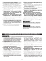
1. Read and understand the warnings posted on the
machine and in this manual. Failure to comply with
all of these warnings may cause serious injury.
2. Replace the warning labels if they become
obscured or removed.
3. This machine is designed and intended for use by
properly trained and experienced personnel only.
If you are not familiar with the proper and safe
operation of a band saw, do not use until proper
training and knowledge have been obtained.
4. Do not use this machine for other than its intended
use. If used for other purposes, DELTA
®
Power
Equipment Corporation disclaims any real or
implied warranty and holds itself harmless from any
injury that may result from that use.
5. Always wear approved safety glasses/face shields
while using this grinder.
6. operating this grinder, remove tie, rings, watches
and other jewelry, and roll sleeves up past the
elbows. Remove all loose clothing and confine long
hair. Non-slip footwear or anti-skid floor strips are
recommended. Do not wear gloves.
7. Wear ear protectors (plugs or muffs) during
extended periods of operation.
8. Some dust created by power sanding, sawing,
grinding, drilling and other construction activities
FAILURE TO FOLLOW THESE RULES MAY RESULT IN SERIOUS INJURY.
contain chemicals known to cause cancer,
birth defects or other reproductive harm. Some
examples of these chemicals are:
• Lead from lead based paint.
• Crystalline silica from bricks, cement and other
masonry products.
• Arsenic and chromium from chemically treated
lumber.
Your risk of exposure varies, depending on how often
you do this type of work. To reduce your exposure to
these chemicals, work in a well-ventilated area and
work with approved safety equipment, such as face or
dust masks that are specifically designed to filter out
microscopic particles.
9. Do not operate this machine while tired or under
the influence of drugs, alcohol or any medication.
10. Make certain the switch is in the OFF position
before connecting the machine to the power
source.
11. Make certain the machine is properly grounded.
12. Make all machine adjustments or maintenance with
the machine unplugged from the power source.
13. Form a habit of checking to see that all extra
continued on page 4
3
5. Always wear approved safety glasses/face shields
while using this tool.
6. Before operating this tool, remove tie, rings,
watches and other jewelry, and roll sleeves up past
the elbows. Remove all loose clothing and confine
long hair. Non-slip footwear or anti-skid floor strips
are recommended. Do not wear gloves.

equipment such as adjusting keys, wrenches,
scrap, stock, and cleaning rags are removed away
from the machine before turning on.
14. Keep safety guards in place at all times when the
machine is in use. If removed for maintenance
purposes, use extreme caution and replace the
guards immediately when maintenance is complete.
15. Make sure the tool is firmly secured to a stable work
surface before use.
16. Check damaged parts. Before further use of the
machine, a guard or other part that is damaged
should be carefully checked to determine that it will
operate properly and perform its intended function.
Check for alignment of moving parts, binding of
moving parts, breakage of parts, mounting and
any other conditions that may affect its operation.
A guard or other part that is damaged should be
properly repaired or replaced.
17. Provide for adequate space surrounding work area
and non-glare, overhead lighting.
18. Keep the floor around the machine clean and free of
scrap material, oil and grease.
19. Keep visitors a safe distance from the work area.
Keep children away.
20. Make your workshop child proof with padlocks,
master switches or by removing starter keys.
21. Give your work undivided attention. Looking
around, carrying on a conversation and “horse-
play" are careless acts that can result in serious
injury.
22. Maintain a balanced stance at all times so that you
do not fall or lean against the tool or its moving
parts. Do not overreach or use excessive force to
perform any machine operation.
23. Use the right tool at the correct speed and feed
rate. Do not force a tool or attachment to do a job
for which it was not designed. The right tool will do
the job better and safer.
24. Use recommended accessories; improper
accessories may be hazardous.
25. Maintain machinery with care. Follow instructions
for lubricating and changing accessories.
26. Turn off the machine before cleaning. Use a brush
or compressed air to remove dust or debris — do
not use your hands.
27. Do not stand on the machine. Serious injury could
occur if the machine tips over.
28. Never leave the machine running unattended. Turn
the power off and do not leave the machine until it
comes to a complete stop.
29. At all times, hold the stock firmly.
30. Do not use this tool for other than it intended use. If
used for other purposes, DELTA
®
Power Equipment
Corporation disclaims any real or implied warranty
and holds itself harmless for any injury or damage
which may result from that use.
Familiarize yourself with the following safety notices
used in this manual:
This means that if precautions are not heeded, it may
result in minor injury and/or possible machine damage.
This means that if precautions are not heeded, it may
result in serious injury or possibly even death.
4
ADDITIONAL SPECIFIC SAFETY RULES
1. DO NOT OPERATE THIS MACHINE until it is
completely assembled and installed according to
the instructions. A machine incorrectly assembled
can cause serious injury.
2. OBTAIN ADVICE from your supervisor, instructor, or
another qualified person if you are not thoroughly
familiar with the operation of this machine.
Knowledge is safety.
3. FOLLOW ALL WIRING CODES and recommended
electrical connections to prevent shock or
electrocution.
4. KEEP KNIVES SHARP and free from rust and pitch.
Dull or rusted knives work harder and can cause
kickback.
5. TIGHTEN THE INFEED/OUTFEED TABLES
before starting the machine. Loss of control of the
workpiece can cause serious injury.
6. PROPERLY SECURE THE BLADES IN THE
CUTTERHEAD before turning the power “ON”.
Loose blades may be thrown out at high speeds.
7. NEVER TURN THE MACHINE “ON” before clearing
the table of all objects (tools, scraps of wood, etc.).
Flying debris can cause serious injury.
8. NEVER TURN THE MACHINE “ON” with the
workpiece contacting the cutterhead. Kickback can
occur.
9. AVOID AWKWARD OPERATIONS AND HAND
POSITIONS. A sudden slip could cause a hand to
move into the cutterhead.
10. KEEP ARMS, HANDS, AND FINGERS away from
the cutterhead to prevent severe injury.
11. NEVER MAKE CUTS deeper than 1/8" (3.2mm) to
prevent kickback.
Failure to follow these rules may result in serious personal injury.

SAVE THESE INSTRUCTIONS.
Refer to them often and use them to instruct others.
5
12. NEVER JOINT OR PLANE A WORKPIECE that
is shorter than 10" (254mm), narrower than 3/4"
(19.0MM), or less than 1/2" (12.7mm) thick. Jointing
smaller workpieces can place your hand in the
cutterhead causing severe injury.
13. USE HOLD-DOWN/PUSH BLOCKS for jointing
or planing any workpiece lower than the fence.
Jointing or planing small workpieces can result in
kickback and severe injury.
14. HOLD THE WORKPIECE FIRMLY against the table
and fence. Loss of control of the workpiece can
cause kickback and result in serious injury.
15. NEVER PERFORM “FREE-HAND” OPERATIONS.
Use the fence to position and guide the workpiece.
Loss of control of the workpiece can cause serious
injury.
16. DO NOT attempt to perform an abnormal or little-
used operation without study and the use of
adequate hold-down/push blocks, jigs, fixtures,
stops, etc.
17. DO NOT FEED A WORKPIECE into the outfeed end
of the machine. The workpiece will be thrown out of
the opposite end at high speeds.
18. DO NOT FEED A WORKPIECE that is warped,
contains knots, or is embedded with foreign objects
(nails, staples, etc.) to prevent kickback.
19. MAINTAIN THE PROPER RELATIONSHIP OF
INFEED AND OUTFEED TABLE SURFACES
and cutterhead knife path. Loss of control of the
workpiece can cause serious injury.
20. PROPERLY SUPPORT LONG OR WIDE
WORKPIECES. Loss of control of the workpiece
can cause injury.
21. NEVER PERFORM LAYOUT, ASSEMBLY, OR
SETUP WORK on the table/work area when the
machine is running. A sudden slip could cause a
hand to move into the cutterhead. Severe injury can
result.
22. TURN THE MACHINE “OFF”, disconnect the
machine from the power source, and clean the
table/work area before leaving the machine. LOCK
THE SWITCH IN THE “OFF” POSITION to prevent
unauthorized use. Someone else might accidentally
start the machine and cause injury to themselves.
23. ADDITIONAL INFORMATION regarding the safe
and proper operation of power tools (i.e. a safety
video) is available from the Power Tool Institute,
1300 Sumner Avenue, Cleveland, OH 44115-2851
(www.powertoolinstitute.com). Information is also
available from the National Safety Council, 1121
Spring Lake Drive, Itasca, IL 60143-3201. Please
refer to the American National Standards Institute
ANSI 01.1 Safety Requirements for Woodworking
Machines and the U.S. Department of Labor OSHA
1910.213 Regulations.
ADDITIONAL SPECIFIC SAFETY RULES

1. All grounded, cord-connected machines:
In the event of a malfunction or breakdown, grounding provides a path of least resistance for electric current to
reduce the risk of electric shock. This machine is equipped with an electric cord having an equipment-grounding
conductor and a grounding plug. The plug must be plugged into a matching outlet that is properly installed and
grounded in accordance with all local codes and ordinances.
Do not modify the plug provided - if it will not fit the outlet, have the proper outlet installed by a qualified electrician.
Improper connection of the equipment-grounding conductor can result in risk of electric shock. The conductor with
insulation having an outer surface that is green with or without yellow stripes is the equipment-grounding conductor.
If repair or replacement of the electric cord or plug is necessary, do not connect the equipment-grounding conductor
to a live terminal.
Check with a qualified electrician or service personnel if the grounding instructions are not completely understood,
or if in doubt as to whether the machine is properly grounded.
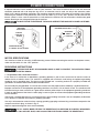
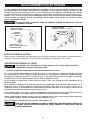
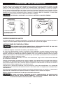
Use only 3-wire extension cords that have 3-prong grounding type plugs and matching 3-conductor receptacles that
accept the machine’s plug, as shown in Fig. A.
Repair or replace damaged or worn cord immediately.
IN ALL CASES, MAKE CERTAIN THE RECEPTACLE IN QUESTION IS PROPERLY GROUNDED.
IF YOU ARE NOT SURE, HAVE A QUALIFIED ELECTRICIAN CHECK THE RECEPTACLE.
GROUNDING INSTRUCTIONS
THIS MACHINE MUST BE GROUNDED WHILE IN USE TO PROTECT THE OPERATOR FROM
ELECTRIC SHOCK.
A separate electrical circuit should be used for your machines. This circuit should not be less than #12 wire and
should be protected with a 20 Amp time lag fuse. If an extension cord is used, use only 3-wire extension cords
which have 3-prong grounding type plugs and matching receptacle which will accept the machine’s plug. Before
connecting the machine to the power line, make sure the switch (s) is in the "OFF" position and be sure that the
electric current is of the same characteristics as indicated on the machine. All line connections should make good
contact. Running on low voltage will damage the machine.
DO NOT EXPOSE THE MACHINE TO RAIN OR OPERATE THE MACHINE IN DAMP LOCATIONS.
FIG. A FIG. B
GROUNDED
OUTLET BOX
CURRENT
CARRYING
PRONGS
GROUNDING BLADE
IS LONGEST OF THE 3 BLADES
GROUNDED OUTLET BOX
GROUNDING
MEANS
ADAPTER
POWER CONNECTIONS
6
MOTOR SPECIFICATIONS
Your machine is wired for 110 volts, 60 HZ alternating current. Before connecting the machine to the power source,
make sure the switch is in the “OFF” position.

EXTENSION CORDS
Use proper extension cords. Make
sure your extension cord is in good
condition and is a 3-wire extension cord which has
a 3-prong grounding type plug and matching
receptacle which will accept the machine’s plug.
When using an extension cord, be sure to use one
heavy enough to carry the current of the machine.
An undersized cord will cause a drop in line
voltage, resulting in loss of power and overheating.
The table shows the correct gauge to use
depending on the cord length. If in doubt, use the
next heavier gauge. The smaller the gauge number,
the heavier the cord.
MINIMUM GAUGE EXTENSION CORD
RECOMMENDED SIZES FOR USE WITH STATIONARY ELECTRIC MACHINES
Ampere
Rating
Volts Total Length
of Cord in
Feet
Gauge of Extension
Cord
0-6
0-6
0-6
0-6
120
120
120
120
up to 25
25-50
50-100
100-150
18 AWG
16 AWG
16 AWG
14 AWG
6-10
6-10
6-10
6-10
120
120
120
120
up to 25
25-50
50-100
100-150
18 AWG
16 AWG
14 AWG
12 AWG
10-12
10-12
10-12
10-12
120
120
120
120
up to 25
25-50
50-100
100-150
16 AWG
16 AWG
14 AWG
12 AWG
12-16
12-16
12-16
120
120
120
up to 25
25-50
14 AWG
12 AWG
GREATER THAN 50 FEET NOT RECOMMENDED
7
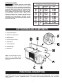
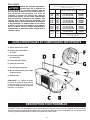
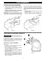
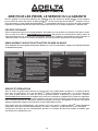
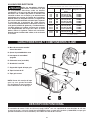
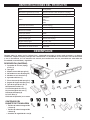
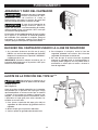
KEY FEATURES AND COMPONENTS
A. Infeed/outfeed table
B. Depth of cut adjustment
C. On/Off switch
D. Cutterhead (not visible)
E. Cutter guard
F. Fence angle lock
G. 45° bevel stop
H. Rear fence
FUNCTIONAL DESCRIPTION
The DELTA
®
37-071 is a 6" Bench Jointer with designed cutting capacity of 6" (152mm) width and 1/8" (3.2mm)
depth. It features a 110-volt, 10,000 RPM motor, an in-and-out, tilting center-mounted fence, and a two-knife
cutterhead.
NOTE: Located within the fence
mount is a red sliding guard.
Please insure guard moves freely
with fence.

8
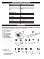
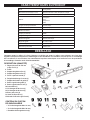
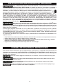
Compare all parts to the list below and check that all parts are present and in good condition. Report any missing
or damaged parts to your distributor or dealer. Prior to tool assembly and use, read this manual thoroughly to
familiarize yourself with proper assembly, maintenance and safety procedures.
PRODUCT SPECIFICATIONS
UNPACKING
DESCRIPTION (QUANTITY)
1. 37-071 6” Jointer (1)
2. Fence
3. Rear Fence Support (1)
4. Rear Fence Bracket (1)
5. Dovetail Clamp (1)
6. Indexing Handle (1)
7. Fence Mounting Plate (1)
8. Fence Angle Lock (1)
9. 45°/90° Angle Stop (1)
10. Hardware Package (1)
11. 4 mm Hex Wrench (1)
12. 6 mm Hex Wrench (1)
13. Push Blocks (2)
14. Dust Chute (1)
15. Operator’s Manual (not shown)
CONTENTS OF
HARDWARE PACK
• M8 x 16mm Hex Head Screws (4)
• M8 x 20mm Hex Head Screws (2)
• 8mm Lock Washers (6)
Weight 76 lbs
Overall Dimensions (L x W x H) 26 x 8 x 10 in.
Table Dimensions (L x W) 28-1/2 in. x 6-¼ in.
Motor
12 amps
120V
Single-Phase
60 Hz
Maximum Width of Cut 6 in.
Maximum Depth of Cut 1/8 in.
Number of Knives 2
Cuts per Minute 20,000
Fence Length 22-7/8 in.
Fence Height 4-5/16 in.
Fence Angle 45°, 90° and 135°
Cutterhead Diameter 1-7/8 in.
Cutterhead Speed 10,000 RPM

9
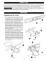
UNPACKING
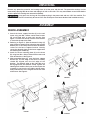
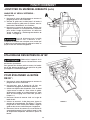
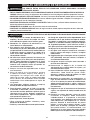
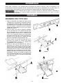
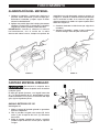
FENCE ASSEMBLY
1. Attach the fence support bracket (A) to the tool
frame using two M8 x 25mm socket head screws
(B), each fitted with an 8mm lock washer. See
Figure 1. Ensure that the top surface of the bracket
is flush with the top of the table.
2. Referring to Figure 2, slide the dovetail clamp (C)
onto the fence support (D) ensuring the tops of both
bottom pins in the clamp are flush with the bottom
surface of the fence support bracket. Loosely
secure the dovetail clamp to the fence support with
the indexing lock handle (E).
3. Attach the fence mounting plate (A) to the fence
(B) using four M8 x 25mm socket head screws and
8mm lock washers. See Figure 3.
4. Slide assembled fence (A) over the fence support
bracket (B). The left edge of the fence assembly
should be aligned with the left edge of the
bracket. The dovetail edge on the right side must
be engaged with the dovetail clamp. Tighten the
indexing lock handle to firmly secure and square the
assembly. Insure that the red sliding guard moves
freely and attaches to the magnets on the rear side
of the fence. See Figure 4.
FIGURE 1
ASSEMBLY
FIGURE 2
Remove any protective materials and coatings from all of the parts and the tool. The protective coatings can be
removed by spraying WD-40 on them and wiping it off with a soft cloth. This may need redone several times before
all of the protective coatings are removed completely.
If any parts are missing, do not attempt to plug in the power cord and turn “ON” the machine. The
machine should only be turned “ON” after all the parts have been obtained and installed correctly.
FIGURE 3
FIGURE 4

10
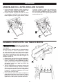
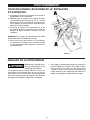
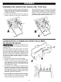
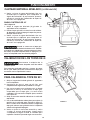
FENCE ANGLE LOCK ASSEMBLY
ALIGN CUTTERHEAD TO OUTFEED TABLE
ASSEMBLY
FIGURE 5 FIGURE 6
FIGURE 7
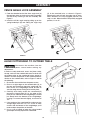
1. Feed the threaded end of the fence angle lock (A)
through both holes in the fence mounting assembly
and secure by screwing it into the assembly. See
Figure 5.
2. Install the 45°/90° angle stop by pulling up on the
spring-loaded pin (B) and sliding the angle stop
Disconnect the machine from the
power source before making any
adjustments!
In order to safely feed stock across the jointer safely,
the top surface of the outfeed table must be level with
the highest point of the cutterhead knives during its
rotation. To check the position of the cutterhead knives
relative to the outfeed table, refer to Figure 7 and do
the following.
1. Disconnect the machine from the power source.
2. Place a straight edge on the outfeed table (A) so
that one end overhangs above the cutterhead. For
best results, the straightedge should be able to
stand on edge without having to be held in place.
3. Carefully and slowly rotate the cutterhead (B)
toward the infeed table (C). As the edge of the
knife passes underneath the straightedge, it should
just barely brush the bottom of the straightedge,
causing it to move forward slightly, no more than
1/8”.
4. If the rotation of the cutterhead lifts and moves the
straight edge more than 1/8” or if it fails to make
contact with the bottom of the straightedge, you’ll
need to adjust the position of the knife.
5. Use a scrap of wood to keep the spring-loaded
guard open and fully-expose the cutterhead.
(C) in the mortised hole, as shown in Figure 6.
Releasing the pin will lock the angle stop in place.
When locked in the fully-engaged position, the
stop is at 90°. When locked in the partially engaged
position, it is at 45°.
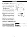
FIGURE 8

11
ASSEMBLY
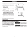
FIGURE 9
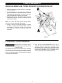
ALIGN CUTTERHEAD TO OUTFEED TABLE (continued)
FIGURE 10
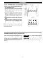
6. Loosen the four screws securing the clamp bar to
the cutterhead. See Figure 8.
7. Locate the two adjustment screws on the exposed
knife. Refer to Figure 9.
8. Rotate the adjustment screws clockwise to lower
the knife or counterclockwise to raise it. Each screw
must be adjusted separately.
9. Re-check the position of the knife on either end
using the straightedge as in Step 3. Continue to
adjust the height of the knife until it brushes the
underside of the straightedge enough to move it
1/8”.
NOTE: Check both the left and right sides of the
cutterhead knife to ensure they are at the proper
height.
10. Replace the clamp bar and tighten the four screws
securing the clamp bar to the cutterhead. Slightly
tighten each of the clamp screws, making sure to
follow the sequence shown in Figure 10.
NOTE: Failure to follow the proper sequence for
tightening the clamp screws may result in the position
of the knife being altered which can affect the
performance of the tool.
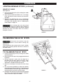
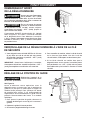
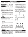
CONNECTING TO DUST COLLECTOR
A jointer creates a large amount of fine particles while
in use. It is strongly recommended that you connect
the jointer to a dust collector. Your DELTA® Bench
Jointer is equipped with a 2-1/4” (OD) dust port which
is located underneath the outfeed table. This must
be connected to a dust collector hose to ensure safe
operation.
Do not attempt to operate this tool
without first connecting it to an
adequate dust collection system.
Always turn on the dust collector
before starting the jointer and always
stop the jointer before turning off the dust collector.

12
Make sure that the switch is in the
"OFF" position before plugging cord
into outlet. Do not touch the plug’s metal prongs when
unplugging or plugging in the cord.
In the event of a power outage (such
as a breaker or fuse trip), always move
the switch to the "OFF" position until the main power is
restored.
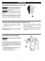
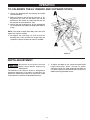
The On/Off switch (A), indicated in Figure 11, is located
on the front of the jointer cabinet. To turn the machine
“ON,” move the switch to the up position. To turn the
machine “OFF,” move the switch to the down position.
OPERATION
STARTING AND STOPPING THE JOINTER
FIGURE 11
LOCKING THE JOINTER USING THE SAFETY KEY
1. Your DELTA
®
6” Bench Jointer uses a safety key
that enables you to lock the tool in the “OFF”
position when not in use.
IMPORTANT: When the machine is not in use, the
switch should be locked in the "OFF" position to
prevent unauthorized use.
2. To lock the machine, remove the safety key by
pulling it straight out. With the safety key removed,
the switch will not operate.
3. Should the safety key be removed while the jointer
is running, the machine can be turned "OFF,"
but cannot be restarted unless the safety key is
re-inserted.
ADJUSTING FENCE POSITION
Disconnect the machine from the
power source before making any
adjustments!
See Figure 12.
Prior to performing any jointer operation, check to
make sure the fence position is approximately the
same as the width of the stock being jointed. For edge
jointing of thinner stock, it is recommended that you
occasionally reposition the fence to avoid dulling the
knives in one area.
1. To adjust the position of the fence, loosen the
indexing lock handle (A) by rotating it to left.
2. Move fence to proper position.
3. Retighten the indexing lock handle.
FIGURE 12

13
OPERATION
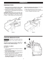
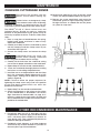
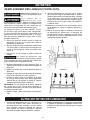
FEEDING STOCK
1. Place the surface to be jointed face down on the
infeed table and against the fence. Turn the jointer
on and wait for the motor to come to full speed.
2. Apply light downward pressure and slowly feed the
stock through the spring-loaded cutter guard and
over the cutting head.
IMPORTANT: When feeding stock horizontally, with
the width of the board laying flat against the table,
always use safety paddles or a push stick, as shown
in Figure 13. When feeding stock vertically, with the
FIGURE 13 FIGURE 14
width of the board flush against the fence, always keep
fingers on top of the board. See Figure 14.
3. Keep moving the board until it clears the cutter.
4. Turn the jointer off and wait for the cutterhead to
come to a stop before removing the stock.
JOINTING BEVELED STOCK
Disconnect the machine from the
power source before making any
adjustments!
The fence can adjust to an inward 45° angle and an
outward 45° angle, enabling you to joint beveled stock.
To adjust the fence tilt, do the following:
OUTWARD 45° ANGLE:
See Figure 15.
1. Loosen the beveling lock by rotating the handle (A)
counterclockwise.
2. Pull the spring-loaded pin (B) up and pull the
45°/90° Stop (C) back slightly.
3. Release the spring-loaded pin and continue pulling
the 45°/90° Stop until it locks in position.
4. Retighten the beveling lock. Use a combination
square or carpenters square to check the tilt angle.
If it needs to be adjusted, refer to “Calibrating the
45°/90° Stops” on page 14.
FIGURE 15

14
OPERATION
JOINTING BEVELED STOCK (continued)
FIGURE 16
INWARD 45° ANGLE:
See Figure 16.
1. Loosen the beveling lock (A) by rotating the handle
counterclockwise.
2. Tip the fence toward the table as far as it will go.
It will stop when the fence contacts the inward 45°
stop bolts.
3. Retighten the beveling lock. Use a combination
square or carpenters square to check the tilt angle.
If it needs to be adjusted, refer to “Calibrating the
45°/90° Stops” on page 14.
When jointing with the fence tilted
inward at 45° feed the stock carefully to
ensure that the workpiece does not become trapped
between the fence and table, which can create a
dangerous situation.
CALIBRATING THE 45°/90° STOPS
Disconnect the machine from the
power source before making any
adjustments!
To ensure precise and accurate results, the 45° and 90°
Stops must accurately position the fence in relation to
the table surface.
TO CALIBRATE THE 90° STOP:
1. Loosen the beveling lock by rotating the handle
counterclockwise.
2. Ensure the 45°/90° Stop is fully-engaged and locked
in position.
3. Using a carpenter’s square, with one edge flat on
the table and the other against the fence, check
to see if the fence and table are in square. If any
adjustment is needed, proceed to step #4.
4. Loosen the retaining nut located on the 90° Stop
rod.
5. Use a flat head screwdriver to adjust the position
of the Stop rod. Refer to Figure 17. Turning the rod
clockwise reduces the fence angle while rotating it
counterclockwise increases the fence angle.
6. Re-tighten the retaining nut and re-lock the beveling
lock. Then re-check the angle using the carpenter’s
square. Continue to adjust as needed.
FIGURE 17

15
FIGURE 18
TO CALIBRATE THE 45° INWARD AND OUTWARD STOPS:
OPERATION
1. Loosen the beveling lock by rotating the handle
counterclockwise.
2. Refer to Figure 18 and locate the two sets of 45°
Stop Bolts (A), there are two bolts that set the
position for the inward 45° Stop and two that set
the position for the outward 45° stop.
3. Loosen the two retaining nuts on the appropriate
set of Stop bolts and adjust the Stop bolts either in
or out.
NOTE: The heads of both Stop bolts must be flush
against the mount assembly.
4. Re-tighten the retaining nut and re-lock the
beveling lock. Then re-check the angle using the
carpenter’s square. Continue to adjust as needed.
DEPTH ADJUSTMENT
Disconnect the machine from the
power source before making any
adjustments!
The DELTA
®
37-071 Bench Jointer is designed to
remove no more than 1/8” of stock in a single pass. For
operations requiring the removal of more stock, make
several passes to achieve the desired dimensions.
1. To adjust the depth of cut, rotate the infeed table
height adjustment wheel. Turning the wheel
clockwise raises the table (reducing the depth of
cut) while rotating it counterclockwise lowers the
table (increasing the depth of cut).

16
MAINTENANCE
CHANGING CUTTERHEAD KNIVES
Disconnect the machine from the
power source before making any
adjustments!
Jointer knives are dangerously sharp.
Use extreme caution when inspecting,
removing, sharpening, or replacing knives into the
cutterhead. Failure to comply may cause serious injury.
The DELTA
®
37-071 6” Bench Jointer uses two
individual knives. Should you notice a significant
decrease in the performance of your jointer, it may be
necessary to replace the knives. To do this, follow these
steps:
1. Place a scrap piece of wood between the spring-
loaded cutter guard and fence in order to fully
expose the cutterhead.
2. Carefully and slowly rotate the cutterhead by hand
until the clamp bar and four clamp screws (A) are
accessible. See Figure 19.
3. Unscrew the clamp screws and remove the clamp
bar.
Cutterhead knives are sharp. Use
caution when handling cutterhead
knives. Use gloves to reduce the risk of injury.
4. Carefully lift the knife from the cutterhead, taking
care to note its proper orientation to the cutterhead.
5. Repeat Steps 2-4 for the second cutterhead knife.
6. Clean the cutterhead thoroughly before installing
new knives or re-installing sharpened knives.
7. Install the new or re-sharpened knife and the clamp
bar in the cutterhead. Slightly tighten each of the
clamp screws, making sure to follow the sequence
shown in Figure 20.
NOTE: Failure to follow the proper sequence for
tightening the clamp screws may result in the position
of the knife being altered which can affect the
performance of the tool.
8. Repeat Step 7 for the second cutterhead knife.
9. Check the alignment on the knives to the surface
of the outfeed table as described in the section
Align Cutterhead to Outfeed table, on page 10. If
necessary, rotate the two jack screws on either end
of the cutterhead knife in order to ensure the knife is
parallel to the outfeed table.
FIGURE 19
FIGURE 20
OTHER RECOMMENDED MAINTENANCE
1. Periodically blow out all air passages with dry
compressed air. All plastic parts should be cleaned
with a soft damp cloth. NEVER use solvents to
clean plastic parts. They could possibly dissolve or
otherwise damage the material.
2. Periodically check tightness on all other hardware
and listen for any unusual vibrations as you work as
these may be a sign of loose hardware.
10. Perform final tightening on each of the four clamp
screws uses the proscribed sequence in Figure 19.
11. Remove the scrap wood block and return the
cutterhead guard to original operating position.
Re-align the fence as needed and test the jointer
on a piece of scrap stock.

ACCESSORIES
A complete line of accessories is available from your DELTA
®
Supplier, DELTA
®
Factory Service Centers, and
DELTA
®
Factory Service Centers, and DELTA
®
Authorized Service Centers. Please visit our Web Site www.
DeltaMachinery.com for an online catalog or for the name or your nearest supplier.
Since accessories other than those offered by DELTA
®
have not been tested with this product,
use of such accessories could be hazardous. For safest operation, only DELTA
®
recommended
accessories should be used with this product.
Five Year Limited New Product Warranty
DELTA
®
will repair or replace, at its expense and at its option, any new DELTA
®
machine, machine part, or machine accessory which in normal
use has proven to be defective in workmanship or material, provided that the customer returns the product prepaid to a DELTA
®
factory service
center or authorized service station with proof of purchase of the product within five years and provides DELTA
®
with reasonable opportunity
to verify the alleged defect by inspection. For all refurbished DELTA
®
product, the warranty period is 180 days. DELTA
®
will not be responsible
for any asserted defect which has resulted from normal wear, misuse, abuse or repair or alteration made or specifically authorized by anyone
other than an authorized DELTA
®
service facility or representative. Under no circumstances will DELTA
®
be liable for incidental or consequential
damages resulting from defective products. Some states do not allow the exclusion or limitation of incidental or consequential damages, so
the above limitation or exclusion may not apply to you. This warranty is DELTA
®
’s sole warranty and sets forth the customer’s exclusive remedy,
with respect to defective products; all other warranties, express or implied, whether of merchantability, fitness for purpose, or otherwise, are
expressly disclaimed by DELTA
®
. For further detail of warranty coverage and warranty repair information, visit www.DeltaMachinery.com or call
1-800-223-7278. This warranty gives you specific legal rights and you may have other rights which vary in certain states or provinces.
WARRANTY
To register your tool for warranty service visit our website at www.DeltaMachinery.com.
LATIN AMERICA: This warranty does not apply to products sold in Latin America. For products sold in Latin America,
see country specific warranty information contained in the packaging, call the local company or see website for warranty
information.
17

REPLACEMENT PARTS
Use only identical replacement parts. For a parts list or to order parts, visit our website at www.DeltaMachinery.
com/service. You can also order parts from your nearest factory-owned branch, Authorized Warranty Service
Center or by calling Technical Service Manager at 1-800-223-7278 to receive personalized support from one of our
highly-trained representatives.
FREE WARNING LABEL REPLACEMENT
If your warning labels become illegible or are missing, call
1-800-223-7278
for a free replacement.
SERVICE AND REPAIRS
All quality tools will eventually require servicing and/or replacement of parts. For information
about DELTA
®
Power Equipment Corporation, its factory-owned branches, or to locate an
Authorized Warranty Service Center, visit our website at www.DeltaMachinery.com/service
or call our Customer Care Center at 1-800-223-7278. All repairs made by our service centers are fully
guaranteed against defective material and workmanship. We cannot guarantee repairs made or attempted by
others. By calling this number you can also find answers to most frequently asked questions.
You can also write to us for information at DELTA
®
Power Equipment Corporation, 2651 New Cut
Road, Spartanburg, SC 29303. - Attention: Technical Service Manager. Be sure to include all of the
information shown on the nameplate of your tool (model number, type, serial number, date code, etc.)
PARTS, SERVICE OR WARRANTY ASSISTANCE
All DELTA
®
machines and accessories are manufactured to high quality standards and are serviced by a network of
DELTA
®
Factory Service Centers and DELTA
®
Authorized Service Centers. To obtain additional information regarding
your DELTA
®
quality product or to obtain parts, service, warranty assistance, or the location of the nearest service
center, please call 1-800-223-7278.
18

19

20
CONSIGNES DE SÉCURITÉ IMPORTANTES
CONSIGNES DE SÉCURITÉ - DÉFINITIONS
ASSUREZ-VOUS D’AVOIR BIEN LU ET COMPRIS TOUTES LES MISES EN GARDE ET LES
CONSIGNES D’UTILISATION AVANT D’UTILISER CET ÉQUIPEMENT. Le fait de ne pas
respecter toutes les instructions ci-dessous pourrait causer une électrocution, des incendies, et/ou des blessures
personnelles ou des dommages matériels graves.
Le travail du bois peut être dangereux si des procédures d’utilisation sécuritaires et adéquates ne sont
pas respectées. Comme c’est le cas pour toute pièce de machinerie, l’utilisation de ce produit comporte
certains dangers. En utilisant cet appareil selon les directives et avec prudence, vous réduirez de façon
importante les risques de blessures corporelles. Cependant, si les précautions normales de sécurité
sont négligées ou ignorées, la personne qui utilise l’appareil pourrait être blessée. L’équipement de protection
comme les gardes, les poussoirs, les dispositifs de retenue, les planches de protection, les lunettes de sécurité,
les masques antipoussières et la protection pour l’ouïe peut réduire le risque de blessure. Cependant, même le
meilleur dispositif de protection ne peut compenser un mauvais jugement, un manque de prudence ou d'inattention.
Utilisez toujours le bon sens et soyez prudent dans l’atelier. Si une manœuvre a l’air dangereuse, ne l’effectuez
pas. Essayez plutôt de trouver un moyen plus facile. RAPPELEZ-VOUS : vous êtes responsable de votre sécurité
personnelle. Pour des renseignements complémentaires, rendez-vous sur notre site Web à l’adresse suivante
www.DeltaMachinery.com.
Cet appareil a été conçu seulement pour certaines utilisations. DELTA
MD
Power Equipment
Corporation recommande fortement que cet appareil ne soit pas modifié ni utilisé pour
toutes autres fins que celles pour lesquelles il a été conçu. Si vous avez des questions sur une utilisation en
particulier, N’UTILISEZ PAS l’appareil avant d’avoir d’abord communiqué avec DELTA
MD
pour déterminer si cette
utilisation peut ou si elle devrait être faite sur ce produit.
Si vous avez des questions relativement à son utilisation, N’UTILISEZ PAS le produit tant que vous n’aurez pas
communiqué par écrit avec DELTA
MD
Power Equipment Corporation et obtenu une réponse de sa part. Contactez-nous
en ligne à www.DeltaMachinery.com ou par courrier à l’adresse suivante : Responsable du service technique, DELTA
MD
Power Equipment Corporation, 2651 New Cut Road, Spartanburg, SC 29303.
Des renseignements au sujet de l’utilisation sécuritaire et appropriée de cet appareil sont disponibles auprès des
sources suivantes :
• Power Tool Institute, 1300 Sumner Avenue, Cleveland, OH 44115-2851 ou en ligne sur www.powertoolinstitute.com
• National Safety Council, 1121 Spring Lake Drive, Itasca, IL 60143-3201
• American National Standards Institute, 25 West 43rd Street, 4 floor, New York, NY 10036 www.ansi.org - ANSI 01.1
Safety Requirements for Woodworking Machines
• Réglementation du Département américain du travail (OSHA) à l’ad
resse www.osha.gov
Ce manuel contient des renseignements qu'il est important de connaître et de comprendre. Ces renseignements ont pour
but d’assurer VOTRE SÉCURITÉ et de PRÉVENIR LES PROBLÈMES D’ÉQUIPEMENT. Pour vous aider à reconnaître ces
renseignements, nous utilisons les symboles ci-dessous. Veuillez lire le manuel et prêter attention à ces sections.
Indique une situation extrêmement dangereuse qui, si elle n’est pas évitée, entraînera la mort ou une
blessure grave.
Indique une situation potentiellement dangereuse qui, si elle n’est pas évitée, pourrait
entraîner la mort ou une blessure grave.
Indique une situation potentiellement dangereuse qui, si elle n’est pas évitée, peut entraîner une
blessure mineure ou modérée.
Utilisé sans le symbole d’avertissement, indique une situation potentiellement dangereuse qui, si elle
n’est pas évitée, peut endommager l’appareil.
La page est en cours de chargement...
La page est en cours de chargement...
La page est en cours de chargement...
La page est en cours de chargement...
La page est en cours de chargement...
La page est en cours de chargement...
La page est en cours de chargement...
La page est en cours de chargement...
La page est en cours de chargement...
La page est en cours de chargement...
La page est en cours de chargement...
La page est en cours de chargement...
La page est en cours de chargement...
La page est en cours de chargement...
La page est en cours de chargement...
La page est en cours de chargement...
La page est en cours de chargement...
La page est en cours de chargement...
La page est en cours de chargement...
La page est en cours de chargement...
La page est en cours de chargement...
La page est en cours de chargement...
La page est en cours de chargement...
La page est en cours de chargement...
La page est en cours de chargement...
La page est en cours de chargement...
La page est en cours de chargement...
La page est en cours de chargement...
La page est en cours de chargement...
La page est en cours de chargement...
La page est en cours de chargement...
La page est en cours de chargement...
La page est en cours de chargement...
La page est en cours de chargement...
La page est en cours de chargement...
La page est en cours de chargement...
-
 1
1
-
 2
2
-
 3
3
-
 4
4
-
 5
5
-
 6
6
-
 7
7
-
 8
8
-
 9
9
-
 10
10
-
 11
11
-
 12
12
-
 13
13
-
 14
14
-
 15
15
-
 16
16
-
 17
17
-
 18
18
-
 19
19
-
 20
20
-
 21
21
-
 22
22
-
 23
23
-
 24
24
-
 25
25
-
 26
26
-
 27
27
-
 28
28
-
 29
29
-
 30
30
-
 31
31
-
 32
32
-
 33
33
-
 34
34
-
 35
35
-
 36
36
-
 37
37
-
 38
38
-
 39
39
-
 40
40
-
 41
41
-
 42
42
-
 43
43
-
 44
44
-
 45
45
-
 46
46
-
 47
47
-
 48
48
-
 49
49
-
 50
50
-
 51
51
-
 52
52
-
 53
53
-
 54
54
-
 55
55
-
 56
56


Delta 37-071 Manuel utilisateur
- Catégorie
- Outils électroportatifs
- Taper
- Manuel utilisateur
- Ce manuel convient également à
dans d''autres langues
- English: Delta 37-071 User manual
- español: Delta 37-071 Manual de usuario
